ABAQUS_实例模拟
Abaqus 焊缝模拟分析实例
BOOKMARKS
SEARCH
3-Dimensional Repair Weld Simulations – Bead on Plate Comparisons
Dr CD Elcoate1, PJ Bouchard2, and Dr MC Smith2
1) Frazer-Nash Consultancy Limited, 1 Trinity Street, College Green, Bristol, BS1 5TE, UK. 2) British Energy Generation Limited, Barnett Way, Barnwood, Gloucester, GL4 3RS, UK. Full 3-dimensional simulation of multi-pass repair welds is now feasible and practical given the development of improved analysis tools (i.e. ABAQUS) and significantly greater computer power. A single weld bead of limited length, deposited on a flat plate, introduces a strongly varying 3dimensional residual stress field that has similar characteristics to a typical repair weld. This simple welded component is therefore a good vehicle to demonstrate new methods and validate thermal and mechanical predictions. This paper presents a series of results that simulate the deposition of a single weld bead on a flat plate. The work exploits newly developed features within ABAQUS (i.e. plastic strain annealing) which have been demonstrated to be robust and efficient and readily extendible to larger and more complex models. Good comparisons are achieved between simultaneous bead laying and moving heat source approaches whilst it is also noted that the simultaneous bead laying methods offer significant modelling advantages in terms of model creation and execution time.
ABAQUS使用例题
2030.1, 0
2010., 0.0000282563
1232.19, 0.00014944
849.073, 0.000257466
660.524, 0.000359008
548.371, 0.000458002
473.404, 0.000555757
同理,依样设定加载梁的尺寸,得到加载梁部件。
这样,第一步部件尺寸设定就完成了。
图4
第二步:部件使用材料的设定
加载梁使用c50混凝土,砌体使用与实验相对应的材料参数。
由于模拟是针对砌体,所以不考虑加载梁的塑性,因此加载梁只设定密度和弹性。
而砌体则以混凝土塑性损伤本构模型来模拟,要设定密度、弹性、混凝土损伤塑性。
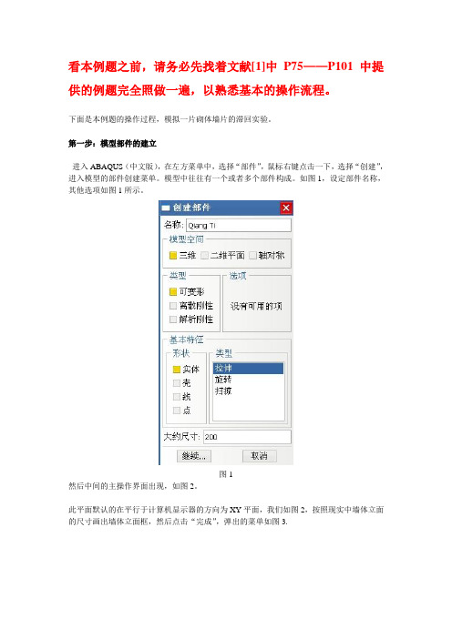
看本例题之前,请务必先找着文献[1]中P75——P101中提供的例题完全照做一遍,以熟悉基本的操作流程。
下面是本例题的操作过程,模拟一片砌体墙片的滞回实验。
第一步:模型部件的建立
进入ABAQUS(中文版),在左方菜单中,选择“部件”,鼠标右键点击一下,选择“创建”,进入模型的部件创建菜单。模型中往往有一个或者多个部件构成。如图1,设定部件名称,其他选项如图1所示。
以上内容中混凝土材料参数的设定参见资料[2],砌体材料参数的设定参见资料[3]。
第三步:将材料属性赋予模型
设定了材料参数后,还要对将材料参数“赋予”模型。其操作菜单如图5
图5
首先建立两个界面SECTION-1和SECTION-2如图5左边红框所示,将两种材料(C50混凝土与砌体材料)“注入”SECTION-1和SECTION-2中,然后点击右边红框中的图标,选择截面所要“赋予”的对象,即可完成材料参数赋予模型的操作。
abaqus实例

一.创建部件1.打开abaqus;开始/程序/Abaqus6.10-1/Abaque CAE 2.Model/Rename/Model-1,并输入名字link43.单击Create part弹出Create part对话框,Name输入link-4;Modeling Space 选择2D PlanarType 选择DeformableBase Feature 选择WireApproximate size 输入800;然后单击continue4.单击(Create Lines:connected)通过点(0,0)、(400,0)、(400,300)、(0,300)单击(CreateLines:connected)连接(400,300)和(0,0)两点,单击提示区中的Done按钮(或者单击鼠标滚轮,也叫中键),形成四杆桁架结构5.单击工具栏中的(Save Model Database),保存模型为link4.cae二.定义材料属性6.双击模型树中的Materials(或者将Module切换到Property,单击Create Material -ε)弹出Edit Material对话框后。
执行对话框中Mechanical/Elasticity/Elastic命令,在对话框底部出现的Data栏中输入Young’s Module为29.5e4,单击OK.完成材料设定。
7.单击“Create Section ”,弹出Create Section对话框,Category中选择Beam;Type中选择Truss;单击continue按钮弹出Edit Section对话框,材料选择默认的Material-1,输入截面积(Cross-sectional area)为100,单击ok按钮。
8.单击Assign Section,框选整个模型,单击鼠标中键,弹出Edit Section Asignment 对话框中,确认Section 后面选择的是刚才创建的Section-1,单击ok,把截面属性Section-1赋予整个模型。
Abaqus焊接模拟的例子
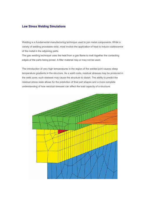
Low Stress Welding SimulationsWelding is a fundamental manufacturing technique used to join metal components. While a variety of welding processes exist, most involve the application of heat to induce coalescence of the metal in the adjoining parts.The gas welding technique uses the heat from a gas flame to melt together the contacting edges of the parts being joined. A filler material may or may not be used.The introduction of very high temperatures in the region of the welded joint causes steep temperature gradients in the structure. As a weld cools, residual stresses may be produced in the weld zone; such stresses may cause the structure to distort. The ability to predict the residual stress state allows for the prediction of final part shapes and a more complete understanding of how residual stresses can affect the load capacity of a structure.The finite element models described in this article represent structural beams. These structures are formed by welding plate sections together rather tha n producing the section directly in a mill. The cross-sectional size of these components can make direct manufacture impractical.The techniques discussed here are based on a generic model but are transferable to a range of applications.Finite Element Analysis ApproachThe simulation uses a sequentially coupled approach in which a thermal analysis is followed by a stress analysis. The temperature results from the thermal analysis are read into the stress analysis as loading to calculate the thermal stress effects. The thermal analysis makes use of ABAQUS user subroutines DFLUX, GAPCON, and FILM. The objective of the simulation is to predict post-weld deformation and residual stress distribution.Figure 1: Mesh of the structure being welded.The model is constructed using solid and shell elements. A solid representation is used in the weld area to ensure more accurate capture of the high solution gradients. Regions outside the weld zone, where thermal gradients are not as severe, are modeled with shell elements toreduce the overall model size. The transition between the shell and solid regions is achieved using tied contact for the thermal analysis and shell-to-solid coupling for the stress analysis. The mesh is shown in Figure 1 (left). The weld bead is shown in red.Thermal Analysis ProcedureThe thermal analysis is performed to calculate the heat transfer resulting from the thermal load of the moving torch. Three user subroutines are activated for the thermal analysis:DFLUX: Used to define the welding torch heat input as a concentrated flux. The heat source travels along the weld line to simulate the torch movement.GAPCON: Used to activate the conduction of heat between the deposited weld material and the parent materials once the torch has passed a given location.FILM: Similar to GAPCON in functionality, but used to activate film coefficients to simulate convective ambient cooling once the torch passes a given location.The simulation is run as a fully transient heat transfer analysis.Structural Analysis ProcedureThe structural analysis uses the thermal analysis (temperature) results as the loading. The objective of the structural analysis is to determine the stresses and strains induced in the weld region during the cooling transient. Boundary conditions are applied to restrain the system against rigid body motion.Figure 2: Nodal temperatures in a typical region of the weld as the torch traverses the weldline.Results and ConclusionTypical thermal results are shown in Figure 2 (left), which displays a contour of nodal temperature as the torch travels along the weld line.The weld is initialized at 1800° C, but no heat is allowed to transfer from the weld until the torch passes. As the torch passes a given point on the weld line, the flux input is initiated, resulting in a localized increase in temperature to more than 2000° C.Figure 3: Transient temperature profile at three points in the torch path.In addition, as the torch passes the same weld line point, conductive and convective heat transfer is activated, causing a rapid drop in temperature as thermal energy is transferred to the surrounding structure and environment.Figure 3 (right) shows the 35 s transient temperature profile at three points close to the start of the torch path. The peak temperature is reached when the torch is activated. A sharp temperature drop is observed after the torch passes.Figure 4: Von Mises stress in the weld region at t=35 s.The stress response of the structure is driven by the high thermal gradients. Figure 4 (left) and Figure 5 (below), respectively, show plots of the von Mises stress and the effective plastic strain approximately 35 s into the process.Figure 5: Effective plastic strain in the weld region at t=35 s.In conclusion, ABAQUS/Standard provides a set of general, flexible modeling tools that allow for the prediction of residual stresses and final shapes in welded components.。
ABAQUS非稳态切削仿真实例

CAE联盟论坛精品讲座系列ABAQUS非稳态切削仿真实例主讲人:fuyun123 ABAQUS板块版主一直想写一个关于ABAQUS非稳态切削的例子,只因为忙,所以一直没机会,近来也有很多人对ABAQUS经典例题上的例子提出了很多问题,为此,今天在此介绍一下非稳态切削的相关内容,主要针对仿真过程分析的要点进行一个阐述,同时回答一下大家的问题,我的理解也不一定正确,大家一起探讨才能促进切削仿真的不断进步。
切削仿真软件的比较:目前用于切削的软件很多,如ABAQUS,LS-DYNA,DEFROM,ADVANTAGE,Marc等,ABAQUS的优势在于非线性处理能力强,有热力耦合的直接分析步,可以对切削过程进行较为准确的仿真分析,目前国际上用的最多,而且由于ABAQUS可以利用子程序和python进行很多定制的开发,从而为问题的解决提供了更好的条件。
LS-DYNA也可以用于切削分析,但是其擅长领域属于碰撞等瞬态动力学分析,现在已经纳入ANSYS麾下,Marc也是一款具有很好非线性的软件,但是切削仿真远没有ABAQUS 方便,而DEFORM在切削,轧制,滚压等领域已经建立起相对完善的仿真界面,但是整体上计算结果好像与实际有些差距,其在切削领域采用的仍为网格重画方法。
而ADVANTAGE在切削领域算是最专业的了,这款软件建立了庞大的切削数据库,而且具有完善的切削,铣削,钻削等加工方法的仿真分析,缺点是材料数据库如果和他的数据有差异,可能比较麻烦。
软件就介绍到这里,下面主要针对ABAQUS的非稳态切削做一下简单的说明,希望能为切削领域探索的各位达人一点启示吧!~~~~~~~~~~~~~~~~~~~~~~~~~~~~~~~~~~~~~~~~~~~~~~~~~~~~~~~~~~~~~~~~~~~~~~~~~~~~此次切削分析,不再建立基于切屑,分离层和工件的模型,整个工件采用一个长方形,而且不再采用ALE法则,本次切削采用拉格朗日准则+失效准则的方法建立切削仿真。
abaqus二维切削仿真实例
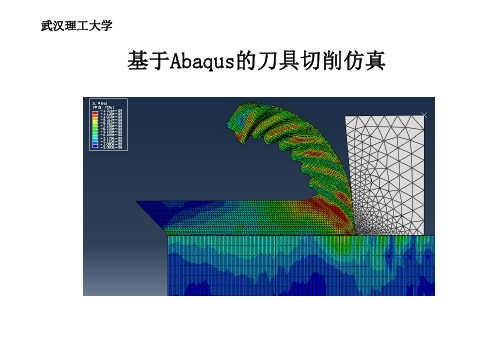
武汉理工大学基于Abaqus的刀具切削仿真Abaqus的功能介绍•线性静力学,动力学和热传导学•非线性和瞬态分析•多体动力学分析Abaqus的界面介绍切削模拟的假设条件本文建立的金属切削加工热力耦合有限元模型是基于以下的假设条件:•刀具是刚体且锋利,只考虑刀具的温度传导;•忽略加工过程中,由于温度变化引起的金相组织及其它的化学变化;•被加工对象的材料是各向同性的;•不考虑刀具、工件的振动;•由于刀具和工件的切削厚度方向上,切削工程中层厚不变,所以按平面应变来模拟;采用单位:N,Pa,m,S,K,J其他零件尺寸如下:•JOINT分离线为切削时切屑与工件分离的部分•零件分开画,材料接触和变形不同,便于赋予不同的材料特性与接触属性•注意每个零件的原点位置,便于装配Abaqus 零件网格划分对整个零件进行自适应网格常用操作:对零件的每条边分布种子网格控制,单元形状指派网格单元类型控制单元属性执行网格划分零件CHIP 网格划分:点击 ,选择上长边,进行边布种,确定弹出图中,选择按个数补种,单元数250接下来,以相同方式按顺时针布种,数目分别为6,20,6,250,20,201.CHIP 网格形状控制:点击 ,,选择整个零件后确定,选择如下图参数 2.CHIP 网格元素类型:点击 ,选择整个零件,参数如下3.最后点击 ,完成网格划分零件分离线,工件网格划分与此相同刀具TOOL网格划分:1.点击边布种,如图,按住shif 选择前刀面与后刀面,使用密度偏离布种 2.控制网格形状,三角形,技术自由3.网格类型与前面类似Abaqus零件网格划分生成网格零件:1.点击菜单栏‘网格’,选择‘创建网格部件’2.取名‘TOOL-MESH’ 3.确定,生成绿色的网格零件4.在道具右上创建一个参考点,便于施加载荷和输出切削力5.其他零件生成网格零件如图常用操作:创建材料,设置材料参数创建截面,将不同的材料参数赋予到不同的截面上指派截面,将不同的截面赋予到不同的部件上管理项,对左边对应项进行编辑、复制、删除等管理,材料名为点击‘通用’选择密度创建材料GH4169的参数:3.点‘力学’、‘塑性’,选择‘与温度有关的数据’,赋予数据4.设置线膨胀系数,,点‘力学’‘膨胀’5.设置热传导率,点‘热学’‘传导率’,输入数据创建材料GH4169的参数:5.点‘热学’‘非弹性热份额’6.点‘热学’‘比热’,输入参数创建材料GH4169_FAIL的参数:1.点,选GH4169,‘复制’,命名‘GH4169_FAIL’2.选‘GH4169_FAIL’,点‘编辑’‘力学’‘延性金属损伤’‘剪切损伤’,破坏机制参数如下3.点‘子选项’‘损伤演化’‘破坏位移参数’如下GH4169_FAIL赋予给分离线,破坏到一定程度,网格开裂创建刀具TOOL-M 的参数:1.刀具‘密度’‘杨氏模量’‘泊松比’如下2.点‘力学’‘膨胀’,设置‘膨胀系数’3.设置‘热传导率’‘比热’设置截面属性:1.点,名称‘Section_CHIP&WORK’,设置如下,继续,材料选择‘GH4169’2.建‘Section_JOINT’,赋予材料‘GH4169_FAIL’3.建‘Section_TOOL’,赋予材料‘TOOL_M’赋予零件截面属性:1.‘部件’栏点选‘CHIP_MESH’,点2.选择整个零件确定后,赋予零件截面属性‘Section_CHIP&WORK’3.同理,赋予其他零件对应的截面属性Abaqus模型装配常用操作:导入模型阵列平移实例旋转实例合并、切割实例Abaqus模型装配1.点击,导入零件2.点,选择实例‘WORKPIECE-MESH’,选右上角作‘起点’,‘JOINT_MESH’右下角作终点确定3.同理,将刀具顶点移到(2E-5,5E-6)常用操作:创建分析步创建场输出创建历程输出对左边对应项进行管理定义分析步:1.点,建分析步‘Unsteady cutting’插在初始步后,参数设置如下2.时间长度设为2E-5,几何非线性设为‘开’切换到‘相互作用’1.通过菜单、视图,只显示零件CHIP2.菜单栏,‘工具’‘创建面’定义接触面:3.表面命名为‘CHIP_BOT’4.其他表面定义(红色线)如下选择如下红色边确定CHIP_ALLJOINT_BOTJOINT_TOPWORK_TOPTOOL_FACE定义接触性质:1.点,命名‘int-con’,继续2.力学分别定义‘切向行为’‘法向行为’3.定义热传导,定义传导率与距离的函数对应关系如下定义接触性质:类似操作分别定义接触PROCESS_CON:增加‘生热’THIRD_CON:摩擦改为零定义接触对:总共有5对接触1.点 ,选择接触的2个面‘CHIP_BOT ’‘CHIP_TOP ’,力学接触为罚接触 ,接触属性为Initial_on2,按相同方法,按实际接触 定义其他4对接触3.定义刀具为刚性约束。
abaqus6.12-典型实例分析

1.应用背景概述随着科学技术的发展,汽车已经成为人们生活中必不可少的交通工具。
但当今由于交通事故造成的损失日益剧增,研究汽车的碰撞安全性能,提高其耐撞性成为各国汽车行业研究的重要课题。
目前国内外许多著名大学、研究机构以及汽车生产厂商都在大力研究节省成本的汽车安全检测方法,而汽车碰撞理论以及模拟技术随之迅速发展,其中运用有限元方法来研究车辆碰撞模拟得到了相当的重视。
而本案例就是取材于汽车碰撞模拟分析中的一个小案例―――保险杠撞击刚性墙。
2.问题描述该案例选取的几何模型是通过导入已有的*.IGS文件来生成的(已经通过Solidworks软件建好模型的),共包括刚性墙(PART-wall)、保险杠(PART-bumper)、平板(PART-plane)以及横梁(PART-rail)四个部件,该分析案例的关注要点就是主要吸能部件(保险杠)的变形模拟,即发生车体碰撞时其是否能够对车体有足够的保护能力?这里根据具体车体模型建立了保险杠撞击刚性墙的有限元分析模型,为了节省计算资源和时间成本这里也对保险杠的对称模型进行了简化,详细的撞击模型请参照图1所示,撞击时保险杠分析模型以2000mm/s的速度撞击刚性墙,其中分析模型中的保险杠与平板之间、平板与横梁之间不定义接触,采用焊接进行连接,对于保险杠和刚性墙之间的接触采用接触对算法来定义。
1.横梁(rail)2.平板(plane)3.保险杠(bumper)4.刚性墙(wall)图2.1 碰撞模型的SolidWorks图图3.1 Create Part From IGS File对话框(3)从【Module】列表中选择【Part】,进入【Part】模块,通过鼠标左键选择模型树中模型Parts(1)下面的bumper_asm部件,并单击鼠标右键选择Copy命令,弹出【Part Copy】对话框如图3.2所示,在【Part Copy】对话框提示区中输入bumper,并在【Copy Options】中选择【Separate disconnected regions into parts】选项,单击【Ok】按钮完成导入几何模型四个部件的分离,这时我们可以看到模型树上模型Parts(1)下有五个部件,分别为bumper_asm、bumper_1、bumper_2、bumper_3、和bumper_4,选择bumper_asm部件单击鼠标右键并选择Delete命令删除此部件,此时模型Parts(1)下只剩下了四个部件,分别为bumper_1、bumper_2、bumper_3、和bumper_4,将部件bumper_1、bumper_2、bumper_3、和bumper_4分别对应更名为wall(刚性墙)如图3.3所示、bumper(保险杠)如图3.4所示、plane(平板)如图3.5所示和rail(横梁)如图3.6所示。
abaqus土木工程实例
abaqus土木工程实例在土木工程中,ABAQUS是一个广泛使用的有限元分析软件,可用于模拟和分析结构的力学行为。
本文将介绍几个ABAQUS在土木工程领域的实例应用,以帮助读者更好地理解和掌握该软件的使用。
二、桥梁结构分析桥梁是土木工程中常见的重要结构,其安全性及承载能力的分析对工程设计至关重要。
利用ABAQUS软件,我们可以对桥梁结构进行静力和动力分析,并评估其在不同荷载情况下的响应行为。
三、地基稳定性分析地基是土木工程中支撑结构的基础,其稳定性对于确保结构的安全性至关重要。
利用ABAQUS软件,我们可以模拟地基的力学行为,如地基沉降、承载能力等,从而评估地基的稳定性,并做出合理的设计和调整。
四、土壤-结构相互作用分析在土木工程中,土壤和结构之间的相互作用对于结构的性能和安全性具有重要影响。
ABAQUS软件可以模拟土壤与结构之间的相互作用,包括土-结构界面的摩擦和接触、土-结构-水的耦合等,从而更准确地评估结构在不同条件下的响应和行为。
五、结构优化设计结构优化设计在土木工程中具有重要的意义,可以有效提高结构的性能和经济性。
利用ABAQUS软件,我们可以进行结构的优化设计,通过调整结构的几何形状、材料和连接方式等参数,以满足给定的性能指标,并使结构在特定条件下具有更好的力学性能。
本文介绍了ABAQUS在土木工程中的几个实例应用,包括桥梁结构分析、地基稳定性分析、土壤-结构相互作用分析和结构优化设计。
通过这些实例,读者可以了解到ABAQUS在土木工程中的重要性和应用价值。
希望本文能对读者在土木工程领域的研究和实践工作中提供一定的指导和帮助。
- 1、下载文档前请自行甄别文档内容的完整性,平台不提供额外的编辑、内容补充、找答案等附加服务。
- 2、"仅部分预览"的文档,不可在线预览部分如存在完整性等问题,可反馈申请退款(可完整预览的文档不适用该条件!)。
- 3、如文档侵犯您的权益,请联系客服反馈,我们会尽快为您处理(人工客服工作时间:9:00-18:30)。
ABAQUS 钢管两端缩径实例模拟
1、首先在UG里面建立三维模型,UG里面导出PARASOLID格式
2、导入刚才UG里面导出的文件进入ABAQUS
对管的材料属性设置见上图所示,模具值设置ELASTIC属性。
3、分别创立模具和管截面属性,然后赋予给模具和管,见下图:
4、按照自己预先计算好的位移建立装配件,图示见下:
5、创建通用分析步,打开几何非线性开关,见下图:
6、为后面接触对创建面:
Interaction里面创建面,Tools-Surface-Creat-选择Geometry,屏幕里面选择如下的两个面:
7、创建接触摩擦系数,这里给0.1,
选择MECHANICAL-TANGENTIAL BEHAIOR,见下图,摩擦系数0.1,点击OK。
8、创建接触对:
选择继续,主面选择模具凹面,从面选择刚才创建的Surface-1面,见下图:
具体选择从面见上面右下角的Surfaces,点击就显示创建的面,选中即可。
创建好的接触对见下图:
9、点击:RP,选择模具上一点,RP为模具创建参考点,然后点击:
把模具创建成刚体,继续选择,见图蓝色阴影部分,
Edit--选择整个模具:,参考点选项:点击Edit--选中刚才创建的参考点。
OK,就把模具变成刚体了。
10、为管创建对称约束,由于成型模拟我们做的是四分之一,所以需要创建两个对称约束:一个Z面的,一个X面的,下图是选择Z的对
称
约
束。
然后OK,即可。
X面的照此。
11、创建模具位移,见下左图选择蓝色部分,点击继续,然后选择模
具参考点,在点击屏幕窗口左下角DONE完
成,出现图,见右
下,打开所有自由
度,修改X方向的
位移为-1000(具体
的位移根据自己设
定值而定):
12、MESH模块里面为模具和管划分网格。
点击:按钮,选择管的轴线方向两条边布种
10,见下图红色高亮两条边,圆弧方向同样布置。
点击,选择厚度方
向两条边,设置为2,标示等分,网格画好后见后图:。
模具可以按照此划分网格,记住比管的网格划分更大即可。
13、JOB模块:创建一个JOB,提交分析即可。