文献翻译-注塑模具
塑料注塑模具中英文对照外文翻译文献
外文翻译及原文(文档含英文原文和中文翻译)【原文一】CONCURRENT DESIGN OF PLASTICS INJECTION MOULDS AbstractThe plastic product manufacturing industry has been growing rapidly in recent years. One of the most popular processes for making plastic parts is injection moulding. The design of injection mould is critically important to product quality and efficient product processing.Mould-making companies, who wish to maintain the competitive edge, desire to shorten both design and manufacturing leading times of the by applying a systematic mould design process. The mould industry is an important support industry during the product development process, serving as an important link between the product designer and manufacturer. Product development has changed from the traditional serial process of design, followed by manufacture, to a more organized concurrent process where design and manufacture are considered at a very early stage of design. The concept of concurrent engineering (CE) is no longer new and yet it is still applicable and relevant in today’s manuf acturing environment. Team working spirit, management involvement, total design process and integration of IT tools are still the essence of CE. The application of The CE process to the design of an injection process involves the simultaneous consideration of plastic part design, mould design and injection moulding machine selection, production scheduling and cost as early as possible in the design stage.This paper presents the basic structure of an injection mould design. The basis of this system arises from an analysis of the injection mould design process for mould design companies. This injection mould design system covers both the mould design process and mould knowledge management. Finally the principle of concurrent engineering process is outlined and then its principle is applied to the design of a plastic injection mould.Keywords :Plastic injection mould design, Concurrent engineering, Computer aided engineering, Moulding conditions, Plastic injection moulding, Flow simulation1.IntroductionInjection moulds are always expensive to make, unfortunately without a mould it can not be possible ho have a moulded product. Every mould maker has his/her own approach to design a mould and there are many different ways of designing and building a mould. Surely one of the most critical parameters to be considered in the design stage of the mould is the number of cavities, methods of injection, types of runners, methods of gating, methods of ejection, capacity and features of the injection moulding machines. Mould cost, mould quality and cost of mould product are inseparableIn today’s completive environment, computer aided mould filling simulation packages can accurately predict the fill patterns of any part. This allows for quick simulations of gate placements and helps finding the optimal location. Engineers can perform moulding trials on the computer before the part design is completed. Process engineers can systematically predict a design and process window, and can obtain information about the cumulative effect of the process variables that influence part performance, cost, and appearance.2.Injection MouldingInjection moulding is one of the most effective ways to bring out the best in plastics. It is universally used to make complex, finished parts, often in a single step, economically, precisely and with little waste. Mass production of plastic parts mostly utilizes moulds. The manufacturing process and involving moulds must be designed after passing through the appearance evaluation and the structure optimization of the product design. Designers face a hugenumber of options when they create injection-moulded components. Concurrent engineering requires an engineer to consider the manufacturing process of the designed product in the development phase. A good design of the product is unable to go to the market if its manufacturing process is impossible or too expensive. Integration of process simulation, rapid prototyping and manufacturing can reduce the risk associated with moving from CAD to CAM and further enhance the validity of the product development.3. Importance of Computer Aided Injection Mould DesignThe injection moulding design task can be highly complex. Computer Aided Engineering (CAE) analysis tools provide enormous advantages of enabling design engineers to consider virtually and part, mould and injection parameters without the real use of any manufacturing and time. The possibility of trying alternative designs or concepts on the computer screen gives the engineers the opportunity to eliminate potential problems before beginning the real production. Moreover, in virtual environment, designers can quickly and easily asses the sensitivity of specific moulding parameters on the quality and manufacturability of the final product. All theseCAE tools enable all these analysis to be completed in a meter of days or even hours, rather than weeks or months needed for the real experimental trial and error cycles. As CAE is used in the early design of part, mould and moulding parameters, the cost savings are substantial not only because of best functioning part and time savings but also the shortens the time needed to launch the product to the market.The need to meet set tolerances of plastic part ties in to all aspects of the moulding process, including part size and shape, resin chemical structure, the fillers used, mould cavity layout, gating, mould cooling and the release mechanisms used. Given this complexity, designers often use computer design tools, such as finite element analysis (FEA) and mould filling analysis (MFA), to reduce development time and cost. FEA determines strain, stress and deflection in a part by dividing the structure into small elements where these parameters can be well defined. MFA evaluates gate position and size to optimize resin flow. It also defines placement of weld lines, areas of excessive stress, and how wall and rib thickness affect flow. Other finite element design tools include mould cooling analysis for temperature distribution, and cycle time and shrinkage analysis for dimensional control and prediction of frozen stress and warpage.The CAE analysis of compression moulded parts is shown in Figure 1. The analysis cycle starts with the creation of a CAD model and a finite element mesh of the mould cavity. After the injection conditions are specified, mould filling, fiber orientation, curing and thermal history, shrinkage and warpage can be simulated. The material properties calculated by the simulation can be used to model the structural behaviour of the part. If required, part design, gate location and processing conditions can be modified in the computer until an acceptable part is obtained. After the analysis is finished an optimized part can be produced with reduced weldline (known also knitline), optimized strength, controlled temperatures and curing, minimized shrinkage and warpage.Machining of the moulds was formerly done manually, with a toolmaker checking each cut. This process became more automated with the growth and widespread use of computer numerically controlled or CNC machining centres. Setup time has also been significantly reduced through the use of special software capable of generating cutter paths directly from a CAD data file. Spindle speeds as high as 100,000 rpm provide further advances in high speed machining. Cutting materials have demonstrated phenomenal performance without the use of any cutting/coolant fluid whatsoever. As a result, the process of machining complex cores and cavities has been accelerated. It is good news that the time it takes to generate a mould is constantly being reduced. The bad news, on the other hand, is that even with all these advances, designing and manufacturing of the mould can still take a long time and can be extremely expensive.Figure 1 CAE analysis of injection moulded partsMany company executives now realize how vital it is to deploy new products to market rapidly. New products are the key to corporate prosperity. They drive corporate revenues, market shares, bottom lines and share prices. A company able to launch good quality products with reasonable prices ahead of their competition not only realizes 100% of the market before rival products arrive but also tends to maintain a dominant position for a few years even after competitive products have finally been announced (Smith, 1991). For most products, these two advantages are dramatic. Rapid product development is now a key aspect of competitive success. Figure 2 shows that only 3–7% of the product mix from the average industrial or electronics company is less than 5 years old. For companies in the top quartile, the number increases to 15–25%. For world-class firms, it is 60–80% (Thompson, 1996). The best companies continuously develop new products. AtHewlett-Packard, over 80% of the profits result from products less than 2 years old! (Neel, 1997)Figure 2. Importance of new product (Jacobs, 2000)With the advances in computer technology and artificial intelligence, efforts have been directed to reduce the cost and lead time in the design and manufacture of an injection mould. Injection mould design has been the main area of interest since it is a complex process involving several sub-designs related to various components of the mould, each requiring expert knowledge and experience. Lee et. al. (1997) proposed a systematic methodology and knowledge base for injection mould design in a concurrent engineering environment.4.Concurrent Engineering in Mould DesignConcurrent Engineering (CE) is a systematic approach to integrated product development process. It represents team values of co-operation, trust and sharing in such a manner that decision making is by consensus, involving all per spectives in parallel, from the very beginning of the productlife-cycle (Evans, 1998). Essentially, CE provides a collaborative, co-operative, collective and simultaneous engineering working environment. A concurrent engineering approach is based on five key elements:1. process2. multidisciplinary team3. integrated design model4. facility5. software infrastructureFigure 3 Methodologies in plastic injection mould design, a) Serial engineering b) Concurrent engineeringIn the plastics and mould industry, CE is very important due to the high cost tooling and long lead times. Typically, CE is utilized by manufacturing prototype tooling early in the design phase to analyze and adjust the design. Production tooling is manufactured as the final step. The manufacturing process and involving moulds must be designed after passing through the appearance evaluation and the structure optimization of the product design. CE requires an engineer to consider the manufacturing process of the designed product in the development phase.A good design of the product is unable to go to the market if its manufacturing process is impossible. Integration of process simulation and rapid prototyping and manufacturing can reduce the risk associated with moving from CAD to CAM and further enhance the validity of the product development.For years, designers have been restricted in what they can produce as they generally have todesign for manufacture (DFM) – that is, adjust their design intent to enable the component (or assembly) to be manufactured using a particular process or processes. In addition, if a mould is used to produce an item, there are therefore automatically inherent restrictions to the design imposed at the very beginning. Taking injection moulding as an example, in order to process a component successfully, at a minimum, the following design elements need to be taken into account:1. . geometry;. draft angles,. Non re-entrants shapes,. near constant wall thickness,. complexity,. split line location, and. surface finish,2. material choice;3. rationalisation of components (reducing assemblies);4. cost.In injection moulding, the manufacture of the mould to produce the injection-moulded components is usually the longest part of the product development process. When utilising rapid modelling, the CAD takes the longer time and therefore becomes the bottleneck.The process design and injection moulding of plastics involves rather complicated and time consuming activities including part design, mould design, injection moulding machine selection, production scheduling, tooling and cost estimation. Traditionally all these activities are done by part designers and mould making personnel in a sequential manner after completing injection moulded plastic part design. Obviously these sequential stages could lead to long product development time. However with the implementation of concurrent engineering process in the all parameters effecting product design, mould design, machine selection, production scheduling,tooling and processing cost are considered as early as possible in the design of the plastic part. When used effectively, CAE methods provide enormous cost and time savings for the part design and manufacturing. These tools allow engineers to virtually test how the part will be processed and how it performs during its normal operating life. The material supplier, designer, moulder and manufacturer should apply these tools concurrently early in the design stage of the plastic parts in order to exploit the cost benefit of CAE. CAE makes it possible to replace traditional, sequential decision-making procedures with a concurrent design process, in which all parties can interact and share information, Figure 3. For plastic injection moulding, CAE and related design data provide an integrated environment that facilitates concurrent engineering for the design and manufacture of the part and mould, as well as material selection and simulation of optimal process control parameters.Qualitative expense comparison associated with the part design changes is shown in Figure 4 , showing the fact that when design changes are done at an early stages on the computer screen, the cost associated with is an order of 10.000 times lower than that if the part is in production. These modifications in plastic parts could arise fr om mould modifications, such as gate location, thickness changes, production delays, quality costs, machine setup times, or design change in plastic parts.Figure 4 Cost of design changes during part product development cycle (Rios et.al, 2001)At the early design stage, part designers and moulders have to finalise part design based on their experiences with similar parts. However as the parts become more complex, it gets rather difficult to predict processing and part performance without the use of CAE tools. Thus for even relatively complex parts, the use of CAE tools to prevent the late and expensive design changesand problems that can arise during and after injection. For the successful implementation of concurrent engineering, there must be buy-in from everyone involved.5.Case StudyFigure 5 shows the initial CAD design of plastics part used for the sprinkler irrigation hydrant leg. One of the essential features of the part is that the part has to remain flat after injection; any warping during the injection causes operating problems.Another important feature the plastic part has to have is a high bending stiffness. A number of feeders in different orientation were added to the part as shown in Figure 5b. These feeders should be designed in a way that it has to contribute the weight of the part as minimum aspossible.Before the design of the mould, the flow analysis of the plastic part was carried out with Moldflow software to enable the selection of the best gate location Figure 6a. The figure indicates that the best point for the gate location is the middle feeder at the centre of the part. As the distortion and warpage of the part after injection was vital from the functionality point of view and it has to be kept at a minimum level, the same software was also utilised to yiled the warpage analysis. Figure 5 b shows the results implying the fact that the warpage well after injection remains within the predefined dimensional tolerances.6. ConclusionsIn the plastic injection moulding, the CAD model of the plastic part obtained from commercial 3D programs could be used for the part performance and injection process analyses. With the aid ofCEA technology and the use of concurrent engineering methodology, not only the injection mould can be designed and manufactured in a very short of period of time with a minimised cost but also all potential problems which may arise from part design, mould design and processing parameters could be eliminated at the very beginning of the mould design. These two tools help part designers and mould makers to develop a good product with a better delivery and faster tooling with less time and money.References1. Smith P, Reinertsen D, The time-to-market race, In: Developing Products in Half the Time. New York, Van Nostrand Reinhold, pp. 3–13, 19912.Thompson J, The total product development organization. Proceedings of the SecondAsia–Pacific Rapid Product Development Conference, Brisbane, 19963.Neel R, Don’t stop after the prototype, Seventh International Conference on Rapid Prototyping, San Francisco, 19974.Jacobs PF, “Chapter 3: Rapid Product Development” in Rapid Tooling: Technologies and Industrial Applications , Ed. Peter D. Hilton; Paul F. Jacobs, Marcel Decker, 20005.Lee R-S, Chen, Y-M, and Lee, C-Z, “Development of a concurrent mould design system: a knowledge based approach”, Computer Integrated Manufacturing Systems, 10(4), 287-307, 19976.Evans B., “Simultaneous Engineering”, Mechanical Engi neering , V ol.110, No.2, pp.38-39, 19987.Rios A, Gramann, PJ and Davis B, “Computer Aided Engineering in Compression Molding”, Composites Fabricators Association Annual Conference , Tampa Bay, 2001【译文一】塑料注塑模具并行设计塑料制品制造业近年迅速成长。
塑料注射成型外文文献翻译、中英文翻译、外文翻译
塑料注射成型外文文献翻译、中英文翻译、外文翻译外文翻译原文:Injection MoldingMany different processes are used to transform plastic granules, powders, and liquids into product. The plastic material is in moldable form, and is adaptable to various forming methods. In most cases thermosetting materials require other methods of forming. This is recognized by the fact that thermoplastics are usually heated to a soft state and then reshaped before cooling. Theromosets, on the other hand have not yet been polymerized before processing, and the chemical reaction takes place during the process, usually through heat, a catalyst, or pressure. It is important to remember this concept while studying the plastics manufacturing processes and polymers used.Injection molding is by far the most widely used process of forming thermoplastic materials. It is also one of the oldest. Currently injection molding accounts for 30% of all plastics resin consumption. Since raw material can be converted by a single procedure, injection molding is suitable for mass production of plastics articles and automated one-step production of complex geometries. In most cases, finishing is not necessary. Typical products include toys, automotive parts, household articles, and consumer electronics goods.Since injection molding has a number of interdependent variables, it is a process of considerable complexity. The success of the injection molding operation is dependent not only in the proper setup of the machine hydraulics, barrel temperaturevariations, and changes in material viscosity. Increasing shot-to-shot repeatability of machine variables helps produce parts with tighter tolerance, lowers the level of rejects, and increases product quality (i.e., appearance and serviceability).The principal objective of any molding operation is the manufacture of products: to a specific quality level, in the shortest time, and using repeatable and fully automaticcycle. Molders strive to reduce or eliminate rejected parts in molding production. For injection molding of high precision optical parts, or parts with a high added value such as appliance cases, the payoff of reduced rejects is high.A typical injection molding cycle or sequence consists of five phases;1. Injection or mold filling2. Packing or compression3. Holding4. Cooling5. Part ejectionPlastic granules are fed into the hopper and through an in the injection cylinder where they are carried forward by the rotating screw. The rotation of the screw forces the granules under high pressure against the heated walls of the cylinder causing them to melt. As the pressure building up, the rotating screw is forced backward until enough plastic has accumulated to make the shot. The injection ram (or screw) forces molten plastic from the barrel, through the nozzle, sprue and runner system, and finally into the mold cavities. During injection, the mold cavity is filled volumetrically. When the plastic contacts the cold mold surfaces, it solidifies (freezes) rapidly to produce theskin layer. Since the core remains in the molten state, plastic follows through the core to complete mold filling. Typically, the cavity is filled to 95%~98% during injection. Then the molding process is switched over to the packing phase.Even as the cavity is filled, the molten plastic begins to cool. Since the cooling plastic contracts or shrinks, it gives rise to defects such as sink marks, voids, and dimensional instabilities. To compensate for shrinkage, addition plastic is forced into the cavity. Once the cavity is packed, pressure applied to the melt prevents molten plastic inside the cavity from back flowing out through the gate. The pressure must be applied until the gate solidifies. The process can be divided into two steps (packing and holding) or may be encompassed in one step(holding or second stage). During packing, melt forced into the cavity by the packing pressure compensates for shrinkage. With holding, the pressure merely prevents back flow of the polymer malt.After the holding stage is completed, the cooling phase starts. During, the part is held in the mold for specified period. The duration of the cooling phase depends primarily on the material properties and the part thickness. Typically, the part temperature must cool below the material’s ejection temperature. While cooling the part, the machine plasticates melt for the next cycle.The polymer is subjected to shearing action as well as the condition of the energy from the heater bands. Once the short is made, plastication ceases. This should occur immediately before the end of the cooling phase. Then the mold opens and the part is ejected.When polymers are fabricated into useful articles they are referred to as plastics, rubbers, and fibers. Some polymers, forexample, cotton and wool, occur naturally, but the great majority of commercial products are synthetic in origin. A list of the names of the better known materials would include Bakelite, Dacron, Nylon, Celanese, Orlon, and Styron.Previous to 1930 the use of synthetic polymers was not widespread. However, they should not be classified as new materials for many of them were known in the latter half of the nineteenth century. The failure to develop them during this period was due, in part, to a lack of understanding of their properties, in particular, the problem of the structure of polymers was the subject of much fruitless controversy.Two events of the twentieth century catapulted polymers into a position of worldwide importance. The first of these was the successful commercial production of the plastic now known as Bakelite. Its industrial usefulness was demonstrated in1912 and in the next succeeding years. T oday Bakelite is high on the list of important synthetic products. Before 1912 materials made from cellulose were available, but their manufacture never provided the incentive for new work in the polymer field such as occurred after the advent of Bakelite. The second event was concerned with fundamental studies of the nature polymers by Staudinger in Europe and by Carohers, who worked with the Du Pont company in Delaware. A greater part of the studies were made during the 1920’s. Staudinger’s work was primarily fundamental. Carother’s achievements led t o the development of our present huge plastics industry by causing an awakening of interest in polymer chemistry, an interest which is still strongly apparent today.The Nature of ThermodynamicsThermodynamics is one of the most important areas ofengineering science used to explain how most things work, why some things do not the way that they were intended, and why others things just cannot possibly work at all. It is a key part of the science engineers use to design automotive engines, heat pumps, rocket motors, power stations, gas turbines, air conditioners, super-conducting transmission lines, solar heating systems, etc.Thermodynamics centers about the notions of energy, the idea that energy is conserved is the first low of thermodynamics. It is starting point for the science of thermodynamics is entropy; entropy provides a means for determining if a process is possible.This idea is the basis for the second low of thermodynamics. It also provides the basis for an engineering analysis in which one calculates the maximum amount of useful that can be obtained from a given energy source, or the minimum amount of power input required to do a certain task.A clear understanding of the ideas of entropy is essential for one who needs to use thermodynamics in engineering analysis. Scientists are interested in using thermodynamics to predict and relate the properties of matter; engineers are interested in using this data, together with the basic ideas of energy conservation and entropy production, to analyze the behavior of complex technological systems.There is an example of the sort of system of interest to engineers, a large central power stations. In this particular plant the energy source is petroleum in one of several forms, or sometimes natural gas, and the plant is to convert as much of this energy as possible to electric energy and to send this energy down the transmission line.Simply expressed, the plant does this by boiling water andusing the steam to turn a turbine which turns an electric generator.The simplest such power plants are able to convert only about 25 percent of the fuel energy to electric energy. But this particular plant converts approximately 40 percent;it has been ingeniously designed through careful application of the basic principles of thermodynamics to the hundreds of components in the system.The design engineers who made these calculations used data on the properties of steam developed by physical chemists who in turn used experimental measurements in concert with thermodynamics theory to develop the property data.Plants presently being studied could convert as much as 55 percent of the fuel energy to electric energy, if they indeed perform as predicted by thermodynamics analysis.The rule that the spontaneous flow of heat is always from hotter to cooler objects is a new physical idea. There is noting in the energy conservation principle or in any other law of nature that specifies for us the direction of heat flow. If energy were to flow spontaneously from a block of ice to a surrounding volume of water, this could occur in complete accord with energy conservation. But such a process never happens. This idea is the substance of the second law of thermodynamics.Clear, a refrigerator, which is a physical system used in kitchen refrigerators, freezers, and air-conditioning units must obey not only the first law (energy conservation) but the second law as well.To see why the second law is not violated by a refrigerator, we must be careful in our statement of law. The second law of thermodynamics says, in effect, that heat never flowsspontaneously from a cooler to a hotter object.Or, alternatively, heat can flow from a cooler to a hotter object only as a result of work done by an external agency. We now see the distinction between an everyday spontaneous process, such as the flow of heat from the inside to the outside of a refrigerator.In the water-ice system, the exchange of energy takes place spontaneously and the flow of heat always proceeds from the water to the ice. The water gives up energy and becomes cooler while the ice receives energy and melts.In a refrigerator, on the other hand, the exchange of energy is not spontaneous. Work provided by an external agency is necessary to reverse the natural flow of heat and cool the interior at the expense of further heating the warmer surroundings.译文:塑料注射成型许多不同的加工过程习惯于把塑料颗粒、粉末和液体转化成最终产品。
注塑模具之模具设计与制造外文文献翻译、中英文翻译
外文翻译:Injection moulding for Mold Design and ManufactureThe mold is the manufacturing industry important craft foundation, in our country, the mold manufacture belongs to the special purpose equipment manufacturing industry. China although very already starts to make the mold and the use mold, but long-term has not formed the industry. Straight stabs 0 centuries 80's later periods, the Chinese mold industry only then drives into the development speedway. Recent years, not only the state-owned mold enterprise had the very big development, the three investments enterprise, the villages and towns (individual) the mold enterprise's development also quite rapidly.Although the Chinese mold industrial development rapid, but compares with the demand, obviously falls short of demand, its main gap concentrates precisely to, large-scale, is complex, the long life mold domain. As a result of in aspect and so on mold precision, life, manufacture cycle and productivity, China and the international average horizontal and the developed country still had a bigger disparity, therefore, needed massively to import the mold every year .The Chinese mold industry except must continue to sharpen the productivity; from now on will have emphatically to the profession internal structure adjustment and the state-of-art enhancement. The structure adjustment aspect, mainly is the enterprise structure to the specialized adjustment, the product structure to center the upscale mold development, to the import and export structure improvement, center the upscale automobile cover mold forming analysis and the structure improvement, the multi-purpose compound mold and the compound processing and the laser technology in the mold design manufacture application, the high-speed cutting, the super finishing and polished the technology, the information direction develops .The recent years, the mold profession structure adjustment and the organizational reform step enlarges, mainly displayed in, large-scale, precise, was complex, the long life, center the upscale mold and the mold standard letter development speed is higher than the common mold product; The plastic mold and the compression casting moldproportion increases; Specialized mold factory quantity and its productivity increase; "The three investments" and the private enterprise develops rapidly; The joint stock system transformation step speeds up and so on. Distributes from the area looked, take Zhujiang Delta and Yangtze River delta as central southeast coastal area development quickly to mid-west area, south development quickly to north. At present develops quickest, the mold produces the most centralized province is Guangdong and Zhejiang, places such as Jiangsu, Shanghai, Anhui and Shandong also has a bigger development in recent years.Although our country mold total quantity had at present achieved the suitable scale, the mold level also has the very big enhancement, after but design manufacture horizontal overall rise and fall industry developed country and so on Yu De, America, date, France, Italy many. The current existence question and the disparity mainly display in following several aspects:(1) The total quantity falls short of demandDomestic mold assembling one rate only, about 70%. Low-grade mold, center upscale mold assembling oneself rate only has 50% about.(2) The enterprise organizational structure, the product structure, the technical structure and the import and export structure does not gatherIn our country mold production factory to be most is from the labor mold workshop which produces assembles oneself (branch factory), from produces assembles oneself the proportion to reach as high as about 60%, but the overseas mold ultra 70% is the commodity mold. The specialized mold factory mostly is "large and complete", "small and entire" organization form, but overseas mostly is "small but", "is specially small and fine". Domestic large-scale, precise, complex, the long life mold accounts for the total quantity proportion to be insufficient 30%, but overseas in 50% above 2004 years, ratio of the mold import and export is 3.7:1, the import and export balances the after net import volume to amount to 1.32 billion US dollars, is world mold net import quantity biggest country .(3) The mold product level greatly is lower than the international standardThe production cycle actually is higher than the international water broadproduct level low mainly to display in the mold precision, cavity aspect and so on surface roughness, life and structure.(4) Develops the ability badly, economic efficiency unsatisfactory our country mold enterprise technical personnel proportion lowThe level is lower, also does not take the product development, and frequently is in the passive position in the market. Our country each mold staff average year creation output value approximately, ten thousand US dollars, overseas mold industry developed country mostly 15 to10, 000 US dollars, some reach as high as 25 to10, 000 US dollars, relative is our country quite part of molds enterprises also continues to use the workshop type management with it, truly realizes the enterprise which the modernized enterprise manages fewTo create the above disparity the reason to be very many, the mold long-term has not obtained the value besides the history in as the product which should have, as well as the most state-owned enterprises mechanism cannot adapt the market economy, but also has the following several reasons: .The mold material performance, the quality and the variety question often can affect the mold quality, the life and the cost, the domestically produced molding tool steel and overseas imports the steel products to compare has a bigger disparity. Plastic,plate, equipment energy balance, also direct influence mold level enhancement.RSP ToolingRapid Solidification Process (RSP) Tooling, is a spray forming technology tailored for producing molds and dies [2-4]. The approach combines rapid solidification processing and netshape materials processing in a single step. The general concept involves converting a mold design described by a CAD file to a tooling master using a suitable rapid prototyping (RP) technology such as stereolithography. A pattern transfer is made to a castable ceramic, typically alumina or fused silica. This is followed by spray forming a thick deposit of tool steel (or other alloy) on the pattern to capture the desired shape, surface texture and detail. The resultant metal block is cooled to room temperature and separated from the pattern. Typically, the deposit’s exterior walls are machined square, allowing it to be used as an insert in a holding block such as a MUD frame [5]. The overall turnaround time for tooling is about three days, stating with a master. Molds and dies produced in this way have been used for prototype and production runs in plastic injection molding and die casting.An important benefit of RSP Tooling is that it allows molds and dies to be made early in the design cycle for a component. True prototype parts can be manufactured to assess form, fit, and function using the same process planned for production. If the part is qualified, the tooling can be run in production as conventional tooling would. Use of a digital database and RP technology allows design modifications to be easily made.Experimental ProcedureAn alumina-base ceramic (Cotronics 780 [6]) was slurry cast using a silicone rubber master die, or freeze cast using a stereolithography master. After setting up, ceramic patterns were demolded, fired in a kiln, and cooled to room temperature. H13 tool steel was induction melted under a nitrogen atmosphere, superheated about100︒C, and pressure-fed into a bench-scale converging/diverging spray nozzle, designed and constructed in-house. An inert gas atmosphere within the spray apparatus minimized in-flight oxidation of the atomized droplets as they deposited onto the tool pattern at a rate of about 200 kg/h. Gas-to-metal mass flow ratio was approximately 0.5.For tensile property and hardness evaluation, the spray-formed material was sectioned using a wire EDM and surface ground to remove a 0.05 mm thickheat-affected zone. Samples were heat treated in a furnace that was purged with nitrogen. Each sample was coated with BN and placed in a sealed metal foil packet as a precautionary measure to prevent decarburization.Artificially aged samples were soaked for 1 hour at temperatures ranging from 400 to 700︒C, and air cooled. Conventionally heat treated H13 was austenitized at 1010︒C for 30 min., air quenched, and double tempered (2 hr plus 2 hr) at 538︒C.Microhardness was measured at room temperature using a Shimadzu Type M Vickers Hardness Tester by averaging ten microindentation readings. Microstructure of the etched (3% nital) tool steel was evaluated optically using an Olympus Model PME-3 metallograph and an Amray Model 1830 scanning electron microscope. Phase composition was analyzed via energy-dispersive spectroscopy (EDS). The size distribution of overspray powder was analyzed using a Microtrac Full Range Particle Analyzer after powder samples were sieved at 200 μm to remove coarse flakes. Sample density was evaluated by water displacement using Archimedes’ principle and a Mettler balance (Model AE100).A quasi 1-D computer code developed at INEEL was used to evaluate multiphase flow behavior inside the nozzle and free jet regions. The code's basic numerical technique solves the steadystate gas flow field through an adaptive grid, conservative variables approach and treats the droplet phase in a Lagrangian manner with full aerodynamic and energetic coupling between the droplets and transport gas. The liquid metal injection system is coupled to the throat gas dynamics, and effects of heat transfer and wall friction are included. The code also includes a nonequilibriumsolidification model that permits droplet undercooling and recalescence. The code was used to map out the temperature and velocity profile of the gas and atomized droplets within the nozzle and free jet regions.Results and DiscussionSpray forming is a robust rapid tooling technology that allows tool steel molds and dies to be produced in a straightforward manner. Each was spray formed using a ceramic pattern generated from a RP master.Particle and Gas BehaviorParticle mass frequency and cumulative mass distribution plots for H13 tool steel sprays are given in Figure 1. The mass median diameter was determined to be 56 μm by interpolation of size corresponding to 50% cumulative mass. The area mean diameter and volume mean diameter were calculated to be 53 μm and 139 μm, respectively. Geometric standard deviation, d=(d84/d16)½ , is 1.8, where d84 and d16 are particle diameters corresponding to 84% and 16% cumulative mass in Figure 1.Figure1. Cumulative mass and mass frequency plots of particles in H13 tool stepsprays.Figure2 gives computational results for the multiphase velocity flow field (Figure 2a), and H13 tool steel solid fraction (Figure2b), inside the nozzle and free jetregions. Gas velocity increases until reaching the location of the shock front, at which point it precipitously decreases, eventually decaying exponentially outside the nozzle. Small droplets are easily perturbed by the velocity field, accelerating inside the nozzle and decelerating outside. After reaching their terminal velocity, larger droplets (〜150 μm) are less perturbed by the flow field due to their greater momentum.It is well known that high particle cooling rates in the spray jet (103-106 K/s) and bulk deposit (1-100 K/min) are present during spray forming [7]. Most of the particles in the spray have undergone recalescence, resulting in a solid fraction of about 0.75. Calculated solid fraction profiles of small (〜30 μm) and large (〜150 μm) droplets with distance from the nozzle inlet, are shown in Figure 2b.Spray-Formed DepositsThis high heat extraction rate reduces erosion effects at the surface of the tool pattern. This allows relatively soft, castable ceramic pattern materials to be used that would not be satisfactory candidates for conventional metal casting processes. With suitable processing conditions, fine surface detail can be successfully transferred from the pattern to spray-formed mold. Surface roughness at the molding surface is pattern dependent. Slurry-cast commercial ceramics yield a surface roughness of about 1 μm Ra, suitable for many molding applications. Deposition of tool steel onto glass plates has yielded a specular surface finish of about 0.076 μm Ra. At the current state of development, dimensional repeatability of spray-formed molds, starting with a common master, is about ±0.2%.Figure 2. Calculated particle and gas behavior in nozzle and free jet regions.(a) Velocity profile.(b) Solid fraction.ChemistryThe chemistry of H13 tool steel is designed to allow the material to withstand the temperature, pressure, abrasion, and thermal cycling associated with demanding applications such as die casting. It is the most popular die casting alloy worldwide and second most popular tool steel for plastic injection molding. The steel has low carbon content (0.4 wt.%) to promote toughness, medium chromium content (5 wt.%) to provide good resistance to high temperature softening, 1 wt% Si to improve high temperature oxidation resistance, and small molybdenum and vanadium additions (about 1%) that form stable carbides to increase resistance to erosive wear[8]. Composition analysis was performed on H13 tool steel before and after spray forming.Results, summarized in Table 1, indicate no significant variation in alloy additions.MicrostructureThe size, shape, type, and distribution of carbides found in H13 tool steel is dictated by the processing method and heat treatment. Normally the commercial steel is machined in the mill annealed condition and heat treated(austenitized/quenched/tempered) prior to use. It is typically austenitized at about 1010︒C, quenched in air or oil, and carefully tempered two or three times at 540 to 650︒C to obtain the required combination of hardness, thermal fatigue resistance, and toughness.Commercial, forged, ferritic tool steels cannot be precipitation hardened becauseafter electroslag remelting at the steel mill, ingots are cast that cool slowly and formcoarse carbides. In contrast, rapid solidification of H13 tool steel causes alloying additions to remain largely in solution and to be more uniformly distributed in the matrix [9-11]. Properties can be tailored by artificial aging or conventional heat treatment.A benefit of artificial aging is that it bypasses the specific volume changes that occur during conventional heat treatment that can lead to tool distortion. These specific volume changes occur as the matrix phase transforms from ferrite to austenite to tempered martensite and must be accounted for in the original mold design. However, they cannot always be reliably predicted. Thin sections in the insert, which may be desirable from a design and production standpoint, are oftentimes not included as the material has a tendency to slump during austenitization or distort during quenching. Tool distortion is not observed during artificial aging ofspray-formed tool steels because there is no phase transformation.注塑模具之模具设计与制造模具是制造业的重要工艺基础,在我国,模具制造属于专用设备制造业。
模具 塑料注射成型 外文翻译 外文文献 英文文献
模具塑料注射成型外文翻译外文文献英文文献XXXThere are many different processing methods used to convert plastic pellets。
powders。
and liquids into final products。
Plastic materials XXX。
thermoplastic materials XXX。
XXX require other methods。
It is XXX.XXX。
It is also the oldest method。
Suddenly。
XXX account for 30% of all XXX suitable for mass n。
when raw materials XXX in a single step of n。
In most cases。
n machiningis not required for such products。
The us products produced include toys。
automotive parts。
household items。
and electronic consumer goods.Because plastic n molds have many variable nships。
it is a complex and us processing process。
The success of XXX appropriate steps。
but on the XXX。
which leads to the n of XXX。
barrel temperature changes。
XXX ns can help ce tolerances。
ce defect rates。
and increase product quality.XXX operator is to produce products that e first-rate products in the shortest time。
模具外文翻译外文文献英文文献注塑模

模具外文翻译外文文献英文文献注塑模The Injection Molding1、The injection moldingInjection molding is principally used for the production of the thermoplastic parts,although some progress has been made in developing a method for injection molding some thermosetting materials.The problem of injection a method plastic into a mold cavity from a reservoir of melted material has been extremely difficult to solve for thermosetting plastic which cure and harden under such conditions within a few minutes.The principle of injection molding is quite similar to that of die-casting.The process consists of feeding a plastic compound in powered or granular form from a hopper through metering and melting stages and then injecting it into a mold.After a brief cooling period,the mold is opened and the solidified part ejected.Injection-molding machine operation.The advantage of injection molding are:(ⅰ)a high molding speed adapter for mass production is possible;(ⅱ)there is a wide choice of thermoplastic materials providing a variety of useful properties;(ⅲ)it is possible to mold threads,undercuts,side holes,and large thin section.2、The injection-molding machineSeveral methods are used to force or inject the melted plastic into the mold.The most commonly used system in the larger machines is the in-line reciprocating screw,as shown in Figure 2-1.The screw acts as a combination injection and plasticizing unit.As the plastic is fed to the rotating screw,it passes through three zones as shown:feed,compression,and metering.After the feed zone,the screw-flight depth is gradually reduced,force theplastic to compress.The work is converted to heat by conduction from the barrel surface.As the chamber in front of the screw becomes filled,it forces the screw back,tripping a limit switch that activates a hydraulic cylinder that forces the screw forward and injects the fluid plastic into the closed mold.An antiflowback valve presents plastic under pressure from escaping back into the screw flight.The clamping force that a machine is capable of exerting is part of the size designation and is measured in tons.A rule-of-thumb can be used to determine the tonnage required for a particular job.It is based on two tons of clamp force per square inch of projected area.If the flow pattern is difficult and the parts are thin,this may have to go to three or four tons.Many reciprocating-screw machines are capable of handing thermosetting plastic materials.Previously these materials were handled by compression or transfer molding.Thermosetting materials cure or polymerize in the mold and are ejected hot in the range of 375°C~410°C.T hermosetting parts must be allowed to cool in the mold in order or remove them without distortion. Thus thermosetting cycles can be faster.Of course the mold must be heated rather than chilled,as with thermoplastics.3、Basic Underfeed MouldA simple mould of this type is shown in Figure3-1,and the description of the design and the opening sequence follows.The mould consists of three basic parts,namely:the moving half,the floating cavity plate and the feed plate respectively.The moving half consists of The moving mould plate assembly,support block,backing plate,ejector assembly and the pin ejection system.Thus the moving half in this design is identical with the moving half of basic moulds.The floating cavity plate,which may be of the integer or insert-bolster design,is located on substantial guide pillars(not shown)fitted in the feed plate.These guide pillars must be of sufficient length to support the floating cavity plate over its full movement and still project to perform the function of alignment between the cavity and core when the mould is being closed.Guide bushes are fitted into the moving mould plate and the floating cavity plate respectively.The maximum movement of the floating cavity plate is controlled by stop or similar device.The moving mould plate is suitably bored to provide a clearance for the stop bolt assembly.The stop bolts must be long enough to provide sufficient space between the feed plate and the floating cavity plate for easy removal of the feed system.The minimum space provide for should be 65mm just sufficient for an operator to remove the feed system by hand if necessary.The desire operating sequence is for the first daylight to occur between the floating cavity plate.This ensures the sprue is pulled from the sprue bush immediately the mouldis opened.T o achieve this sequence,springs may be incorporated between the feed plate and the floating cavity plate.The springs should be strong enough to give an initial impetus to the floating cavity plate to ensure it moves away with the moving half.It is normal practice to mount the springs on the guide pillars(Figure3-2)and accommodate them in suitable pocket in the cavity plate.The major part of the feed system(runner and sprue)is accommodated in the feed plate to facilitate automatic operation,the runner should be of a trapezoidal form so that once it is pulled from the feed plate is can easily beextracted.Note that if a round runner is used,half the runner is formed in the floating cavity plate,where it would remain,and be prevented from falling or being wiped clear when the mould is opened.Now that we have considered the mould assembly in the some detail,we look at the cycle of operation for this type of mould.The impressions are filled via the feed system(Figure3-1(a))and after a suitable dwell period,the machine platens commence to open.A force is immediately exerted by the compression springs,which cause the floating cavity plate to move away with the moving half as previously discussed.The sprue is pulled from the sprue bush by the sprue puller.After the floating cavity plate has moved a predetermined distance,it is arrested by the stop bolts.The moving half continues to move back and the moldings,having shrunk on to the cores,are withdrawn from the cavities.The pin gate breaks at its junction with the runner(Figure3-1(b)).The sprue puller,being attached to the moving half,is pulled through the floating cavity plate and thereby release the feed system which is then free to fall between the floating cavity plate and the feed plate.The moving half continues to move back until the ejector system is operated and the moldings are ejected (Figure3-1(c)).When the mould is closed,the respective plates are returned to their molding position and the cycle is repeated.4、Feed SystemIt is necessary to provide a flow-way in the injection mould to connect the nozzle(of the injection machine)to each impression.This flow-way is termed the feed system.Normally thefeed system comprises a sprue,runner and gate.These terms applyequally to the flow-way itself,and to the molded material which is remove from the flow-way itself in the process of extracted the molding.A typical feed system for a four-impression,two plate-type mould is shown in Figure4-1.It is seen that the material passes through the sprue,main runner,branch runner and gate before entering the impression.As the temperature of molten plastic is lowered which going through the sprue and runner,the viscosity will rise;however,the viscosity is lowered by shear heat generated when going through the gate to fill the cavity.It is desirable to keep the distance that the material has to travel down to a minimum to reduce pressure and heat losses.It is for this reason that careful consideration must be given to the impression layout gate’s design.4.1.SprueA sprue is a channel through which to transfer molten plastic injected from the nozzle of the injector into the mold.It is a part of sprue bush,which is a separate part from the mold.4.2.RunnerA runner is a channel that guides molten plastic into the cavity of a mold.4.3.GateA gate is an entrance through which molten plastic enters the cavity.The gate has the following function:restricts the flow and the direction of molten plastic;simplifies cutting of a runner and moldings to simplify finishing of parts;quickly cools and solidifies to avoid backflow after molten plastic has filled up in the cavity.4.4.Cold slug wellThe purpose of the cold slug well,shown opposite the sprue,is theoretically to receive the material that has chilled at the front of nozzle during the cooling and ejection phase.Perhaps of greater importance is the fact that it provides position means whereby the sprue bush for ejection purposes.The sprue,the runner and the gate will be discarded after a part is complete.However,the runner and the gate are important items that affect the quality or the cost of parts.5、EjectionA molding is formed in mould by injecting a plastic melt,under pressure,into animpression via a feed system.It must therefore be removed manually.Furthermore,all thermoplastic materials contract as they solidify,which means that the molding will shrink on to the core which forms it.This shrinkage makes the molding difficult to remove. Facilities are provided on the injection machine for automatic actuation of an ejector system,and this is situated behind the moving platen.Because of this,the mould’s ejector system will be most effectively operated if placed in the moving half of the mould,i.e. the half attached to the moving platen.We have stated previously that we need to eject the molding from the core and it therefore follows that the core,too,will most satisfactorily be located in the moving half.The ejector system in a mould will be discussed under three headings,namely:(ⅰ)the ejector grid;(ⅱ)the ejector plate assembly; and(ⅲ)the method of ejection.5.1、Ejector gridThe ejector grid(Figure5-1)is that part of the mould which supports the mould plate and provides a space into which theejector plate assembly can be fitted and operated.The grid normally consists of a back plate on to which is mounted a number of conveniently shaped “support blocks”.The ejector plate assembly is that part of the mould to which the ejector element is attached.The assembly is contained in a pocket,formed by the ejector grid,directly behind the mould plate.The assembly(Figure5-2)consists of an ejector plate,a retaining plate and an ejector rod.One end of this latter member is threaded and it is screwed into the ejector plate.In this particular design the ejector rod function not only as an actuating member but also as a method of guiding the assembly.Note that the parallel portion of the ejector rod passes through an ejector rod bush fitted in the back plate of the mould.5.2、Ejection techniquesWhen a molding cools,it contracts by an amount depending on the material being processed.For a molding which has no internal form,for example,a solid rectangular block,the molding will shrink away from the cavity walls,thereby permitting a simple ejection technique to be adopted.However,when the molding has internal form,the molding,as it cools,will shrink onto the core and some positive type of ejection is necessary.The designer has several ejection techniques from which to choose,but in general,the choice will be restricted depending upon the shape of the molding.The basic ejection techniques are as follows:(ⅰ)pin ejection(ⅱ)sleeve ejection(ⅲ)stripper plate ejection and(Ⅳ)air ejection.Figure 2-1aFigure 2-1bFigure 3-1Figure 3-2Figure 4-1aFigure 4-1bFigure 5-1Figure 5-2注塑模1、注塑模尽管成型某些热固性材料的方法取得了一定的进步,但注塑模主要(还是)用来生产热塑性塑件。
注塑模具设计与制造外文文献翻译
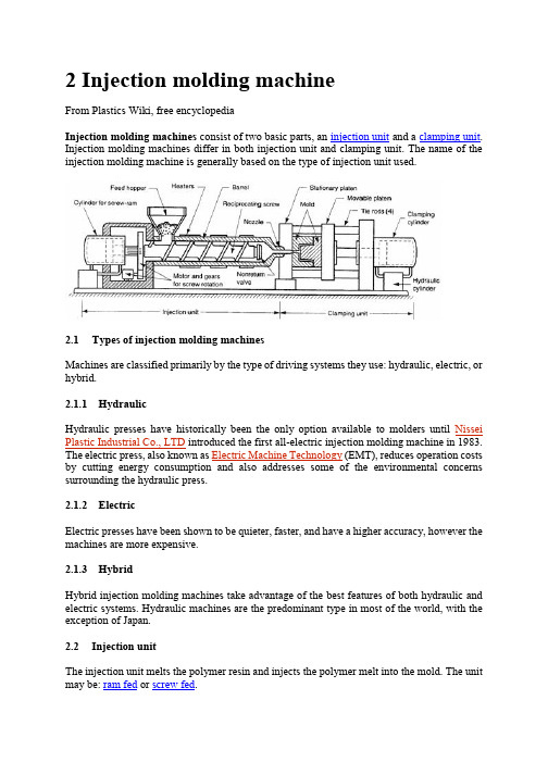
2 Injection molding machineFrom Plastics Wiki, free encyclopediaInjection molding machines consist of two basic parts, an injection unit and a clamping unit. Injection molding machines differ in both injection unit and clamping unit. The name of the injection molding machine is generally based on the type of injection unit used.2.1Types of injection molding machinesMachines are classified primarily by the type of driving systems they use: hydraulic, electric, or hybrid.2.1.1HydraulicHydraulic presses have historically been the only option available to molders until Nissei Plastic Industrial Co., LTD introduced the first all-electric injection molding machine in 1983. The electric press, also known as Electric Machine Technology (EMT), reduces operation costs by cutting energy consumption and also addresses some of the environmental concerns surrounding the hydraulic press.2.1.2ElectricElectric presses have been shown to be quieter, faster, and have a higher accuracy, however the machines are more expensive.2.1.3HybridHybrid injection molding machines take advantage of the best features of both hydraulic and electric systems. Hydraulic machines are the predominant type in most of the world, with the exception of Japan.2.2Injection unitThe injection unit melts the polymer resin and injects the polymer melt into the mold. The unit may be: ram fed or screw fed.The ram fed injection molding machine uses a hydraulically operated plunger to push the plastic through a heated region. The high viscosity melt is then spread into a thin layer by a "torpedo" to allow for better contact with the heated surfaces. The melt converges at a nozzle and is injected into the mold.Reciprocating screw A combination melting, softening, and injection unit in an injection molding machine. Another term for the injection screw. Reciprocating screws are capable of turning as they move back and forth.The reciprocating screw is used to compress, melt, and convey the material. The reciprocating screw consists of three zones (illustrated below):•feeding zone•compressing zone•metering zoneWhile the outside diameter of the screw remains constant, the depth of the flights on the reciprocating screw decreases from the feed zone to the beginning of the metering zone. These flights compress the material against the inside diameter of the barrel, which creates viscous (shear) heat. This shear heat is mainly responsible for melting the material. The heater bands outside the barrel help maintain the material in the molten state. Typically, a molding machine can have three or more heater bands or zones with different temperature settings.Injection molding reciprocating screw An extruder-type screw rotates within a cylinder, which is typically driven by a hydraulic drive mechanism. Plastic material is moved through the heated cylinder via the screw flights and the material becomes fluid. The injection nozzle is blocked by the previous shot, and this action causes the screw to pump itself backward through the cylinder. (During this step, material is plasticated and accumulated for the next shot.) When the mold clamp has locked, the injection phase takes place. At this time, the screw advances, acting as a ram. Simultaneously, the non-return valve closes off the escape passages in the screw and the screw serves as a solid plunger, moving the plastic ahead into the mold. When the injection stroke and holding cycle is completed, the screw is energized to return and the non-return valve opens, allowing plastic to flow forward from the cylinder again, thus repeating the cycle.2.2.1Feed hopperThe container holding a supply molding material to be fed to the screw. The hopper located over the barrel and the feed throat connects them.2.2.2Injection ramThe ram or screw that applies pressure on the molten plastic material to force it into the mold cavities.2.2.3Injection screwThe reciprocating-screw machine is the most common. This design uses the same barrel for melting and injection of plastic.The alternative unit involves the use of separate barrels for plasticizing and injecting the polymer. This type is called a screw-preplasticizer machine or two-stage machine. Plastic pellets are fed from a hopper into the first stage, which uses a screw to drive the polymer forward and melt it. This barrel feeds a second barrel, which uses a plunger to inject the melt into the mold. Older machines used one plunger-driven barrel to melt and inject the plastic. These machines are referred to as plunger-type injection molding machines.2.2.4BarrelBarrel is a major part that melts resins transmitted from hopper through screws and structured in a way that can heat up resins to the proper temperature. A band heater, which can control temper atures in five sections, is attached outside the barrel. Melted resins are supplied to the mold passing through barrel head, shot-off nozzle, and one-touch nozzle.2.2.5Injection cylinderHydraulic motor located inside bearing box, which is connected to injection cylinder load, rotates screw, and the melted resins are measures at the nose of screw. There are many types of injection cylinders that supply necessary power to inject resins according to the characteristics of resins and product types at appropriate speed and pressure. This model employs the double cylinder type. Injection cylinder is composed of cylinder body, piston, and piston load.2.3Clamping unitThe clamping unit holds the mold together, opens and closes it automatically, and ejects the finished part. The mechanism may be of several designs, either mechanical, hydraulic or hydromechanical.Toggle clamps - a type clamping unit include various designs. An actuator moves the crosshead forward, extending the toggle links to push the moving platen toward a closed position. At the beginning of the movement, mechanical advantage is low and speed is high; but near the end of the stroke, the reverse is true. Thus, toggle clamps provide both high speed and high force at different points in the cycle when they are desirable. They are actuated either by hydraulic cylinders or ball screws driven by electric motors. Toggle-clamp units seem most suited to relatively low-tonnage machines.Two clamping designs: (a) one possible toggle clamp design (1) open and (2) closed; and (b) hydraulic clamping (1) open and (2) closed. Tie rods used to guide movuing platens not shown.Hydraulic clamps are used on higher-tonnage injection molding machines, typically in the range 1300 to 8900 kN (150 to 1000 tons). These units are also more flexible than toggle clamps in terms of setting the tonnage at given positions during the stroke.Hydraulic Clamping System is using the direct hydraulic clamp of which the tolerance is still and below 1 %, of course, better than the toggle system. In addition, the Low Pressure Protection Device is higher than the toggle system for 10 times so that the protection for the precision and expensive mold is very good. The clamping force is focus on the central for evenly distribution that can make the adjustment of the mold flatness in automatically. Hydromechanical clamps -clamping units are designed for large tonnages, usually above 8900 kN (1000 tons); they operate by (1) using hydraulic cylinders to rapidly move the mold toward closing position, (2) locking the position by mechanical means, and (3) using high pressure hydraulic cylinders to finally close the mold and build tonnage.2.3.1Injection moldThere are two main types of injection molds: cold runner (two plate and three plate designs) and hot runner– the more common of the runnerless molds.2.3.2Injection platensSteel plates on a molding machine to which the mold is attached. Generally, two platens are used; one being stationary and the other moveable, actuated hydraulically to open and close the mold. It actually provide place to mount the mould. It contains threaded holes on which mould can be mounted using clamps.2.3.3Clamping cylinderA device that actuates the chuck through the aid of pneumatic or hydraulic energy.2.3.4Tie BarTie bars support clamping power, and 4 tie bars are located between the fixing platen and the support platen.3 Injection mouldFrom Wikipedia, the free encyclopediaMold A hollow form or cavity into which molten plastic is forced to give the shape of the required component. The term generally refers to the whole assembly of parts that make up the section of the molding equipment in which the parts are formed. Also called a tool or die. Moulds separate into at least two halves (called the core and the cavity) to permit the part to be extracted; in general the shape of a part must be such that it will not be locked into the mould. For example, sides of objects typically cannot be parallel with the direction of draw (the direction in which the core and cavity separate from each other). They are angled slightly; examination of most household objects made from plastic will show this aspect of design, known as draft. Parts that are "bucket-like" tend to shrink onto the core while cooling and, after the cavity is pulled away, are typically ejected using pins. Parts can be easily welded together after moulding to allow for a hollow part (like a water jug or doll's head) that couldn't physically be designed as one mould.More complex parts are formed using more complex moulds, which may require moveable sections, called slides, which are inserted into the mould to form particular features that cannot be formed using only a core and a cavity, but are then withdrawn to allow the part to be released. Some moulds even allow previously moulded parts to be re-inserted to allow a new plastic layer to form around the first part. This system can allow for production of fully tyred wheels.Traditionally, moulds have been very expensive to manufacture; therefore, they were usually only used in mass production where thousands of parts are being produced.Molds require: Engineering and design, special materials, machinery and highly skilled personnel to manufacture, assemble and test them.Cold-runner moldCold-runner mold Developed to provide for injection of thermoset material either directly into the cavity or through a small sub-runner and gate into the cavity. It may be compared to the hot-runner molds with the exception that the manifold section is cooled rather than heated to maintain softened but uncured material. The cavity and core plates are electrically heated to normal molding temperature and insulated from the cooler manifold section.3.1.1Types of Cold Runner MoldsThere are two major types of cold runner molds: two plate and three plate.3.1.2Two plate moldA two plate cold runner mold is the simplest type of mold. It is called a two plate mold because there is one parting plane, and the mold splits into two halves. The runner system must be located on this parting plane; thus the part can only be gated on its perimeter.3.1.3Three plate moldA three plate mold differs from a two plate in that it has two parting planes, and the mold splits into three sections every time the part is ejected. Since the mold has two parting planes, the runner system can be located on one, and the part on the other. Three plate molds are used because of their flexibility in gating location. A part can be gated virtually anywhere along its surface.3.1.4AdvantagesThe mold design is very simple, and much cheaper than a hot runner system. The mold requires less maintenance and less skill to set up and operate. Color changes are also very easy, since all of the plastic in the mold is ejected with each cycle.3.1.5DisadvantagesThe obvious disadvantage of this system is the waste plastic generated. The runners are either disposed of, or reground and reprocessed with the original material. This adds a step in the manufacturing process. Also, regrind will increase variation in the injection molding process, and could decrease the plastic's mechanical properties.3.1.6Hot runner moldHot-runner mold -injection mold in which the runners are kept hot and insulated from the chilled cavities. Plastic freezeoff occurs at gate of cavity; runners are in a separate plate so they are not, as is the case usually, ejected with the piece.Hot runner molds are two plate molds with a heated runner system inside one half of the mold.A hot runner system is divided into two parts: the manifold and the drops. The manifold has channels that convey the plastic on a single plane, parallel to the parting line, to a point abovethe cavity. The drops, situated perpendicular to the manifold, convey the plastic from the manifold to the part.3.1.7Types of Hot Runner MoldsThere are many variations of hot runner systems. Generally, hot runner systems are designated by how the plastic is heated. There are internally and externally heated drops and manifolds.3.1.8Externally heated hot runnersExternally heated hot runner channels have the lowest pressure drop of any runner system (because there is no heater obstructing flow and all the plastic is molten), and they are better for color changes none of the plastic in the runner system freezes. There are no places for material to hang up and degrade, so externally heated systems are good for thermally sensitive materials.3.1.9Internally heated hot runnersInternally heated runner systems require higher molding pressures, and color changes are very difficult. There are many places for material to hang up and degrade, so thermally sensitive materials should not be used. Internally heated drops offer better gate tip control. Internally heated systems also better separate runner heat from the mold because an insulating frozen layer is formed against the steel wall on the inside of the flow channels.3.1.10 insulated hot runnersA special type of hot runner system is an insulated runner. An insulated runner is not heated; the runner channels are extremely thick and stay molten during constant cycling. This system is very inexpensive, and offers the flexible gating advantages of other hot runners and the elimination of gates without the added cost of the manifold and drops of a heated hot runner system. Color changes are very easy. Unfortunately, these runner systems offer no control, and only commodity plastics like PP and PE can be used. If the mold stops cycling for some reason, the runner system will freeze and the mold has to be split to remove it. Insulated runners are usually used to make low tolerance parts like cups and frisbees.3.1.11 DisadvantagesHot-runner mold is much more expensive than a cold runner, it requires costly maintenance, and requires more skill to operate. Color changes with hot runner molds can be difficult, since it is virtually impossible to remove all of the plastic from an internal runner system.3.1.12 AdvantagesThey can completely eliminate runner scrap, so there are no runners to sort from the parts, and no runners to throw away or regrind and remix into the original material. Hot runners are popular in high production parts, especially with a lot of cavities.Advantages Hot Runner System Over a Cold Runner System include:•no runners to disconnect from the molded parts•no runners to remove or regrind, thus no need for process/ robotics to remove them•having no runners reduces the possibility of contamination•lower injection pressures•lower clamping pressure•consistent heat at processing temperature within the cavity•cooling time is actually shorter (as there is no need for thicker, longer-cycle runners)•shot size is reduced by runner weight•cleaner molding process (no regrinding necessary)•nozzle freeze and sprue sticking issues eliminated中文翻译注塑模具设计与制造2 注射机选自《维基百科》注射机由两个基本部分组成,注射装置和夹紧装置。
文献翻译-注塑模具设计

编号:毕业设计(论文)外文翻译(译文)学院:机电工程学院专业:机械制造及其自动化学生姓名:学号:指导教师单位:姓名:职称:2014年 5 月26 日摘录巨大线束网络的塑料装饰构件集成的发现在汽车领域上是降低汽车重量的一个很有吸引力的方式。
当任何异物插入注射成型的部分,在聚合物中横截面的变化导致了缩痕是审美缺陷而不是塑料装饰是可以接受的组件。
在本文中,插入成型采用注射成型过程分量的方法来减少或消除缩痕线。
采用L9正交试验设计实验框架用来研究工艺参数的影响,部分的肋的几何形状,并在水槽的标记线本身存在的形成。
水槽深度被定义为在表面轮廓可以感觉到的剩余的偏转。
一个描述性的模拟研究提出在不同的肋的几何形状的观察水池深度标记的工艺参数、模具温度、熔体温度和包装的时间是不同的。
仿真结果表明,较高的模具温度可有效地最小化的下沉深度为所有的肋的几何形状,而熔体温度和包时间的影响取决于特定的肋的几何形状。
研究结果还表明,适当的组合肋的几何形状和工艺参数消除了水槽标记。
感谢我要感谢我的导师David C. Angstadt 博士的指导和在这个项目的整个过程中的信任和支持。
Angstadt 博士的不断的反馈和很高的期望,驱使我不断进取,完成这项工作。
我衷心感谢Mica Grujicic博士让我进入Moldflow。
特别感谢我的研究生同学Peiman Mosaddegh 和Celina Renner这项工作的过程中的无私帮助。
我还要感谢我的朋友Nitendra Nath,Gayatri Keskar,Sonia Ramnani,Shyam Panyam,Judhajit Roy 和Ajit Kanda的不断鼓励和帮助。
最后,我要感谢我的家人和朋友们所有的爱和关怀,如果没有这些的话,这项工作将是不完整的。
第一章引言汽车制造商正越来越多地用塑料解决方案来减轻重量。
最近的一项研究表明,塑料占了10%的汽车的总重量。
塑料在汽车从内部的保险杠到外部的门体都存在。
注塑模具设计技术中英文对照外文翻译文献
中英文资料对照外文翻译英文:Design and Technology of the Injection Mold1、3D solid model to replace the center layer modelThe traditional injection molding simulation software based on products of the center layer model. The user must first be thin-walled plastic products abstract into approximate plane and curved surface, the surface is called the center layer. In the center layer to generate two-dimensional planar triangular meshes, the use of these two-dimensional triangular mesh finite element method, and the final result of the analysis in the surface display. Injection product model using3D solid model, the two models are inconsistent, two modeling inevitable. But because of injection molding product shape is complex and diverse, the myriads of changes from athree-dimensional entity, abstraction of the center layer is a very difficult job, extraction process is very cumbersome and time-consuming, so the design of simulation software have fear of difficulty, it has become widely used in injection molding simulation software the bottleneck.HSCAE3D is largely accepted3D solid / surface model of the STL file format. Now the mainstream CAD/CAM system, such as UG, Pro/ENGINEER, CATIA and SolidWorks, can output high quality STL format file. That is to say, the user can use any commercial CAD/CAE systems to generate the desired products3D geometric model of the STL format file, HSCAE3D can automatically add the STL file into a finite element mesh model, through the surface matching and introduction of a new boundary conditions to ensure coordination of corresponding surface flow, based on3D solid model of analysis, and display of three-dimensional analysis results, replacing the center layer simulation technology to abstract the center layer, and then generate mesh this complicated steps, broke through system simulation application bottlenecks, greatly reducing the burden of user modeling, reduces the technical requirement of the user, the user training time from the past few weeks shorter for a fewhours. Figure 1 is based on the central layer model and surface model based on 3D solid / flow analysis simulation comparison chart.2、Finite element, finite difference, the control volume methodsInjection molding products are thin products, products in the thickness direction of size is much smaller than the other two dimensions, temperature and other physical quantities in the thickness direction of the change is very large, if the use of a simple finite element and finite difference method will cause analysis time is too long, can not meet the actual needs of mold design and manufacturing. We in the flow plane by using finite element method, the thickness direction by using finite difference method, were established and plane flow and thickness directions corresponding to the size of the grid and coupling, while the accuracy is guaranteed under the premise of the calculation speed to meet the need of engineering application, and using the control volume method is solved. The moving boundary problem in. For internal and external correspondence surface differences between products, can be divided into two parts the volume, and respectively formed the control equation, the junction of interpolation to ensure thatthe two part harmony contrast.3、Numerical analysis and artificial intelligence technologyOptimization of injection molding process parameters has been overwhelming majority of mold design staff concerns, the traditional CAE software while in computer simulation of a designated under the conditions of the injection molding conditions, but is unable to automatically optimize the technical parameters. Using CAE software personnel must be set to different process conditions were multiple CAE analysis, combined with practical experience in the program were compared between, can get satisfactory process scheme. At the same time, the parts after the CAE analysis, the system will generate a large amount of information about the project ( product, process, analyzes the results ), which often results in a variety of data form, requiring the user to have the analysis and understanding of the results of CAE analysis ability, so the traditional CAE software is a kind of passive computational tools, can provide users with intuitionistic, effective engineering conclusion, to software users demand is too high, the influence of CAE system in the larger scope of application and popularization. In view of the above, HSCAE3D software in the original CAE system based on accurate calculationfunction, the knowledge engineering technology is introduced the system development, the use of artificial intelligence is the ability of thinking and reasoning, instead of the user to complete a large number of information analysis and processing work, directly provide guiding significance for the process of conclusions and recommendations, effectively solve the CAE of the complexity of the system and the requirements of the users of the contradiction between, shortening of the CAE system and the distance between the user, the simulation software by traditional " passive" computational tools to " active" optimization system. HSCAE3D system artificial intelligence technology will be applied to the initial design, the results of the analysis of CAE interpretation and evaluation, improvement and optimization analysis of3 aspects.译文:注塑模具设计的技术1.用三维实体模型取代中心层模型传统的注塑成形仿真软件基于制品的中心层模型。
- 1、下载文档前请自行甄别文档内容的完整性,平台不提供额外的编辑、内容补充、找答案等附加服务。
- 2、"仅部分预览"的文档,不可在线预览部分如存在完整性等问题,可反馈申请退款(可完整预览的文档不适用该条件!)。
- 3、如文档侵犯您的权益,请联系客服反馈,我们会尽快为您处理(人工客服工作时间:9:00-18:30)。
附页1:英文及中文翻译英文1.Example 24,Injection Mold for an Angle FitingIf ejectors are located behind movable side sores or slides ,the ejector plate return safety checks whether the ejectors have been returned to the molding position.If this is not the case,the molding cycle is interrupted.This safety requires a switch on the mold that is actuated when the ejector plate is in the retracted position. The ejector plate return safety thus functions only if the molding cycle utilizes platen preposition, i.e..,after the molded parts have been ejected, the clamping unit closes to the point at which the ejector plate is returned to the molding position by spring force. Only then does the control system issue the “close mold”command. In molds requiring a long ejector stroke, spring return of the ejector plate is often not sure enough. For such cases, there is an ejector return mechanism that fulfills this function.Attachment of the ejector plate return safety is shown in Figs.1 to 7.This single-cavity mold is used to produce an angle fitting.Two long side cores meet at an angle of 90°.The somewhat shorter side core is pulled by a cam pin,while the longer core is pulled by a slide.The difficulty is that blade ejectors are located under the two cores and must be returned to the molding position after having Ejected the finished part before the two cores are set as the mold closes and possibly damage the blade ejectors .Possible consequences include not only broken blade ejectors but also a damaged cavity. Either of these could result in a lengthy interruption of production. For this reason, a helical spring that permits operation with platen prepostion is placed on the ejector rod. This spring then returns the ejector plate .To ensure proper operation, a microswitch is mounted to the clamping plate,while a pin that actuates the switch is mounted in the ejector plate.After connecting the cable with the switch housing of the movable clamping plate,the ejector plate return safety is complete.Example 25,Mold for Bushings with Concealed Gating2.Example 25, Mold for Bushings with Concealed GatingAflanged bushing is to be injection molded in such a way that any remnants ofthe gate are concealed or as inconspicuous as possible.The bushing would normally require a two-plate mold with a single parting line,The molded part would then be released and ejected along its axis, which coincides with the opening direction of the mold. The gate would be located on the outer surface of the flange since it is in contact with the mold parting line.In order to satisfy the requirement for an “invisible”gate,the cavities (two rows of four) are placed between slides carrying the cores even though there are no undercuts.From a central sprue the melt flows through conical runners in the cores to pinpoint gates located on the inner surface of the bushings. As the slides move during opening of the mold the gates are cleanly sheared off flush with the adjacent part surface. The flexibility of the plastic selected is sufficient to permit release of the end of the runner from the angled runner channel.The parts are now free and can drop out of the mold.3. Example 26,Injection Mold for the Valave Housing of a Water-Mixing Tap Made from PolyacetalA valve housing had to be designed and produced for a water-mixing tap.The problem when designing the tool resulted from the undercuts in four directions.Originally occurring considerable differences in wall thicknesses have been eliminated during optimization. Demands for high precision of the cylindrical vave seat in parti-cular wer negatively influenced by various recesses in the wall and adjoining partitions,which favored sink marks and ovalness.Polyaceta (POM) had been chosen as molding materia.The complete molded part had to have homogeneous walls,and be free from flow lines if at all possible, as it would be subjected to ever-changing contact with hot and cold water during an estimated long life span.Inadequately fused weld lines would be capable of developoing into weak spots and wer therefore to be avoided at all cost.Provision has been made for an electrically heated sprue bushing in order to avoid a long sprue,provide better movement energies for the melt and maintain its temperature until it enters the cavity.The resultant very short runner leads to the gate on the edge of the pipelike housing, to be hidden by a part that is subsequently fitted to cover it.The gating,the predetermined mold temperature,the wall thickness at the critical positions and the resultant shrinkage have been employed as the basis for dimensioning the part-forming components.Two cores each cross in the pipe-shaped housing,i.e.one core each penetrates another core.This obviously presents a danger spot should the minutest deviation occur from the specified time and movement-based coordination as well as from the accuracy in the mold.The hollow cores are kept in position by mechanical delay during the first phase of mold opening,while the crossing cores are each withdrawn by an angle pin . Mechanical actuation has been preferred over a hydraulic or pneumatic one in this case in order to exclude the danger of a sequencing error (the so-called human factor) during set-up and operation.The cores consist of a beryllium-copper alloy. They are cooled by heat conducting pins.4.Example 29,Injection Mold for the Housing of a Polypropylene Vegetable DicerMolded PartThe housing accommodates a cutting disc that is driven by a hand crank . The shaft of the crank drive is located in a bore in the housing. The underneath of the housing has a recess for accommodating a suction cap to attach the device to a table. The top of the housing has a filling shaft which supplies the cutting disc with the vegetables to be diced. A feed hopper will be attached to this filling shaft.The molded part weighs 386 g.MoldThe mold was designed so that the dicing chamber lies in the mold-opening direction.The housing base,the filling shaft and two other apertures are ejected with the aid of splits ,a core puller and slides.The slide,moved by the angle pin,forms the inside contour of the housing base .In the closed position,the split shoulder lies against punch and so forms the bore for attaching the suction cap to the housing base .The cylindrical slide lies in the mold parting line and each half is enclosed by the mold plates and.Guide strips lead the slide on the mold plate. The slide supports itself against the effect of the cavity pressure via the adjusting plate and the wedge. Bending of the wedge is prevented by the adjusting plate and the mold plate. The vegetable filling shaft and the passage to the dicing chamber are formed by the mobile core. Its movement is provided by the angle pin.Figure 7 shows the core guide in the guide strip.The inserted core is locked via the wedge and adjusting plate .The guide strip forms a rectangular opening in theside wall of the housing which lies half over and half under the mold parting line. It is moved by two angle pins and is locked in the closed state by two bolts. A guide strip which is bolted and doweled to the mold plate is guided in a T-solt.Finally, a slit has to be formed in the housing wall that penetrates a reinforcement there. Rectangular aperture and reinforcement are formed by the slide which is actuated by the angle pin and locked by the wedge.Two bars serve to guide the slide on the mold plate. Since the angle pins traverse out from the slide ,the core and the guide bars on mold opening, each is provided with ball catches that keep these guide elements in the “open” position. Bars and rolls support the plate on the clamp plate.Runner System/GatingThe sprue bushing lies on the axis of the housing bore, which accommodates the blade drive shaft.The end of the sprue bushing forms the face of an eye inside the dicing chamber that is a part of the crankshaft mount. A core pin protrudes into the bore of the sprue bushing and divides the sprue into three pinpoint gates.Mold Temperature ControlThe coolant is guided in bores and cooling channels in the mold plates, inserts and punches.The splits and offer sufficient space for accommodating cooling channels..Part Release/EjectionOn mold opening,the angle pins on the fixed mold side push the splits ,cores and slides on the moving side so far outward that they release the undercuts of the housing. The molded part remanis on the moving mold side.Ejector pins and ejector sleeve push the molded part out of the ejector-side mold cavities and off core pin. Since the ejector pins are contour-forming,they must be secured against twisting . On mold closing, the ejector system is brought into the injection molding position by ejector-plate return pins and buffer pins,and so too are the splits ,cores and slides by their respective angle pints.译文1.注塑模具角度为拟合如果喷射器是可移动的侧后面疮或幻灯片位于顶针板返回安全的喷射器是否已返回成型,这是不是这样,成型周期检查中断。