外文翻译终极版6[1].9
外文翻译---6 数字数据传输:接口和调制解调器

英文资料及中文翻译6 TRANSMISSIONS OF DIGITAL DATA:INTERFACES AND MODEMS(From Introduction to Data Communications and Net Working,Behrouz Forouzan)Once we have encoder our information into a format that can be transmitted, the next step is to investigate the transmission process itself. Information-processing equipment such as PCs generate encoded signals but ordinarily require assistance to transmit those signals over a communication link. For example, a PC generates a digital signal but needs an additional device to modulate a carrier frequency before it is sent over a telephone line. How do we relay encoded data from the generating device to the next device in the process? The answer is a bundle of wires, a sort of mini communication link, called an interface.Because an interface links two devices not necessarily made by the same manufacturer, its characteristics must be defined and standards must be established. Characteristics of an interface include its mechanical specifications (how many wires are used to transport the signal); its electrical specifications (the frequency, amplitude, and phase of the expected signal); and its functional specifications (if multiple wires are used, what does each one do?). These characteristics are all described by several popular standards and are incorporated in the physical layer of the OSI model.6.1 DIGITAL DATA TRANSMISSIONOf primary concern when considering the transmission of data from one device to another is the wiring. And of primary concern when considering the wiring is the data stream. Do we send one bit at a time, or do we group bits into larger groups and, if so, how? The transmission of binary data across a link can be accomplished either in parallel mode or serial mode. In parallel mode, multiple bits are sent with each clock pulse. In serial mode, one bit is sent with each clock pulse. While there is only one way to send parallel data, there are two subclasses of serial transmission: synchronous and asynchronous (see Figure 6-1).Parallel TransmissionBinary data, consisting of 1s and 0s, may be organized into groups of n bits each. Computers produce and consume data in groups of bits much as we conceive of and use spoken language in the form of words rather than letters. By grouping, we cansend data n bits at a time instead of one. This is called parallel transmission.The mechanism for parallel transmissionis a conceptually simple one: use n wires to send n bits at one time. That way each bit has its own wire, and all n bits of one group can be transmitted with each clock pulse from one device to another. Figure 6-2 shows how parallel transmission works for n=8.Typically the eight wires are bundled in a cable with a connector at each end.Figure 6-2 Parallel transmissionThe advantage of parallel transmission is speed. All else being equal, parallel transmission can increase the transfer speed by a factor of n over serial transmission. But there is a significant disadvantage:cost. Parallel transmission requires n communication lines (wires in the example) just to transmit the data stream. Because this is expensive, parallel transmission is usually limited to short distances, up to a maximum of say 25 feet.Serial TransmissionIn serial transmission one bit follows another, so we need only one communication channel rather than n to transmit data between two communicating devices .The advantage of serial over parallel transmission is that with only one communication channel, serial transmission reduces the cost of transmission over parallel by roughly a factor of n.Since communication within devices is parallel, conversion devices are required at the interface between the sender and the line (parallel-to-parallel).Serial transmission occurs in one of two ways: asynchronous or synchronous. Asynchronous TransmissionAsynchronous transmission is so named because the timing of a signal is unimportant. Instead, information is received and translated by agreed-upon patterns. As long as those patterns are followed, the receiving device can retrieve the information without regard to the rhythm in which it is sent. Patterns are based on grouping the bit stream into bytes. Each group, usually eight bits, is sent along the link as a unit. The sending system handles each group independently, relaying it to the link whenever ready, without regard to a timer.Without a synchronizing pulse, the receiver cannot use timing to predict when the next group will arrive. To alert the receiver to the arrival of a new group, therefore, an extra bit is added to the beginning of each byte. This bit, usually a 0, is called the start bit. To let the receiver know that the byte is finished, one or more additional bits are appended to the end of the byte. These bits, usually 1s, are called stop bits. By this method, each byte is increased in size to at least 10 bits, of which 8 are information and 2 or more are signals to the receiver. In addition, the transmission of each byte may then be followed by a gap of varying duration. This gap can be represented either by an idle channel or by a stream of additional stop bits.In asynchronous transmission we send one start bit (0) at the beginning and one or more stop bits (1s) at the end of each byte. There may be a gap between each byte.The start and stop bits and the gap alert the receiver to the beginning and end of each byte and allow it to synchronize with the data stream. This mechanism is called asynchronous because, at the byte level, sender and receiver do not have to be synchronized. But within each byte, the receiver must still be synchronized with the incoming bit stream. This is, some synchronization is required, but only for the duration of a single byte. The receiving device resynchronizes at the onset of each new byte. When the receiver detects a start bit, it sets a timer and begins counting bits as they come in. after n bits the receiver looks for a stop bit. As soon as it detects the stop bit, it ignores any received pulses until it detects the next start bit.Asynchronou s here means “asynchronous at the byte level,” but the bits are still synchronized; their durations are the same.The addition of stop and start bits and the insertion of gaps into the bit stream make asynchronous transmission slower than forms of transmission that can operate without the addition of control information. But it is cheap and effective, two advantages that make it an attractive choice for situations like low-speed communication. For example, the connection of a terminal to a computer is a natural application for asynchronous transmission. A user types only one character at a time, types extremely slowly in data processing terms, and leaves unpredictable gaps of time between each character.Synchronous TransmissionIn synchronous transmission, the bit stream is combined into longer “frames,” which may contain multiple bytes. Each byte, however, is introduced onto the transmission link without a gap between it and the next one. It is left to the receiver to separate the bit stream into bytes for decoding purposes. In other words, data are transmitted as an unbroken string of 1s and 0s, and the receiver separates that string into the bytes, or characters, it needs to reconstruct the information.In synchronous transmission we send bits one after another without start/stop bits or gaps. It is the responsibility of the receiver to group the bits.Without gaps and start/stop bits, there is no built-in mechanism to help the receiving device adjust its bit synchronization in midstream. Timing becomes very important, therefore, because the accuracy of the received information is completely dependent on the ability of the receiving device to keep an accurate count of the bits as they come in.The advantage of synchronous transmission is speed. With no extra bits or gaps to introduce at the sending end and remove at the receiving end and, by extension, with fewer bits to move across the link, synchronous transmission is faster than asynchronous transmission is faster than asynchronous transmission. For this reason, it is more useful for high-speed applications like the transmission of data from one computer to another. Byte synchronization is accomplished in the data link layer.6.2 DTE-DCE INTERFACAt this point we must clarify two terms important to computer networking: data terminal equipment (DTE). There are usually four basic functional units involved in the communication of data: a DTE and DCE on one end and a DCE and DTE on theother end. The DTE generates the data and passes them, along with any necessary control characters, to a DCE. The DCE does the job of converting the signal to a format appropriate to the transmission medium and introducing it onto the network link. When the signal arrives at the receiving end, this process is reversed.Data Terminal Equipment (DTE)Data terminal equipment (DTE) includes any unit that functions either as a source of or as a destination for binary digital data. At the physical layer, if can be a terminal, microcomputer, computer, printer, fax machine, or any other device that generates or consumes digital data. DTEs do not often communicate directly with one another, they generate and consume information but need an intermediary to be able to communicate. Think of a DTE as operating the way your brain does when you talk. Let’s say you have an idea that you want to communicate to a friend. Your brain creates the idea but cannot transmit that idea to your friend’s brain by itself. Unfortunately or fortunately, we are not a species of mind readers. Instead, your brain passes the idea to your vocal chords and mouth, which convert it to sound waves that can travel through the air or over a telephone line to your friend’s ear and from there to his or her brain, where it is converted back into information. In this model, your brain and your friend’s brain are DTEs. Your vocal chords and mouth are your DCE. His or her ear is also a DCE. The air or telephone wire is your transmission medium.A DTE is any device that is a source of or destination for binary digital data. Data Circuit-Terminating Equipment (DCE)Data circuit-terminating equipment (DCE) includes any functional unit that transmits or receives data in the form of an analog or digital signal through a network. At the physical layer, a DCE takes data generated by a DTE, converts them to an appropriate signal, and then introduces the signal onto the telecommunication link. Commonly used DCEs at this layer include modems . In any network, a DTE generates digital data and passes it to a DCE; the DCE converts the data to a form acceptable to the transmission medium and sends the converted signal to another DCE on the network. The second DCE takes the signal off the line, converts it to a form usable by its DTE, and delivers it. To make this communication possible, both the sending and receiving DCEs must use the same encoding method, much the way that if you want to communicate to someone who understands only Japanese, you must speak Japanese. The two DTEs do not need to be coordinated with each other, but each of them must be coordinated with its own DCE and the DCEs must becoordinated so that data translation occurs without loss of integrity.A DCE is any device that transmits or receives data in the form of an analog or digital signal through a network.6 数字数据传输:接口和调制解调器(选自«数据通信与网络», Behrouz Forouzan著)我们将信息编码成可以传输的格式,下一步就是探讨传输过程了。
外文翻译中英对照版
VOLUME 30 ISSUE 2 October 2008Journal of Achievements in Materials and Manufacturing EngineeringCopyright by International OCSCO World Press. All rights reserved.2008 151 Research paper 2008年十月期2卷30材料与制造工程成果期刊版权所有:国际OCSCO 世界出版社。
一切权利保有。
2008 ??151研究论文1. Introduction Friction stir welding (FSW) is a new solid-state welding method developed by The Welding Institute (TWI) in 1991 [1]. The weld is formed by the excessive deformation of the material at temperatures below its melting point, thus the method is a solid state joining technique. There is no melting of the material, so FSW has several advantages over the commonly used fusion welding techniques [2-10].1.导言摩擦搅拌焊接(FSW)是焊接学?会于1991年研发的一种新型固态焊接方法。
这种焊接?是由材料在低于其熔点的温度上过量变形形成,因此此技术是一种固态连接技术。
材料不熔化,所以FSW 相比常用的熔化焊接技术有若干优势。
例如,在焊接区无多孔性或破裂,工件(尤其薄板上)没有严重扭曲,并且在连接过程中不需要填料、保护气及昂贵的焊接准备there is no significant distortion of the workpieces (particularly in thin plates), and there is no need for filler materials, shielding gases and costly weld preparation during this joining process. FSW被认为是对若干材料例如铝合金、镁合金、黄铜、钛合金及钢最显著且最有潜在用途的焊接技术FSW is considered to be the most remarkable and potentially useful welding technique for several materials, such as Al-alloys, Mg-alloys, brasses, Ti-alloys, and steels [1-16]. 然而,在FSW过程中,用不合适的焊接参数能引起连接处失效,并且使FSW连接处的力学性能恶化。
外文资料译文
CliffhangerLawrenceHargrave路是Wollongong北部一条沿海的路,它是澳洲,New South Wales 风景最优美的路之一, 并且是一个主要的旅游胜地。
路的一个900m截面并且是路的最高的倾斜风险部分在整个国家, 由于岩石掉落和堤防失败的悠久历史。
Richard High报告关于一条壮观的供选择的路线的建筑。
修造在19 世纪60 年代路直到1947 年才作为更低的沿海路被人们知道, 当这改名劳为Lawrence Hargrave Drive (LHD) 。
出生在格林威治,英国在1850年,Lawrence Hargrave 是航空先驱,发明者, 探险家, 泥工和天文学家。
1984年, 他成为了第一人在澳洲飞行,在附近的Stanwell公园。
并且安排沿海路改名以纪念他。
Hargrave 的面孔首先出现在AU$20笔记, 1966年发布。
最初,土轨道,LHD许多年中运载了比较少量的车辆。
在21 世纪作为地方社区和旅游业增长, 大约每天3000辆车在路上行驶。
在2003年8月,随着一项独立研究,发现了路对于公共安全形成了“不可抵御的风险”,负责认为路宣布了一个大修项目为LHD。
在2003年11月,为了加速建筑和压低费用,公路和交通当局(RTA)形成了建筑联盟——Lawrence・Hargrave驱动联盟(LHDA),与Barclay・Mowlem, Coffey Geosciences和Maunsell Austrlia。
建筑在2004年6月开始在AU$ 4900 m 部分的百万(US$ 37 百万)替换在Clifton 和Coalcliff 之间。
并且路预计在2006 年的早期通车。
在项目中心是二座桥梁, 你跨过南部的海湾和其他中间陆岬, 将连接形成一座唯一665 m 长的桥梁。
路线然后将回到现有的对准线通过北海湾。
新路, 包括桥梁, 将有两个3.5 米宽的车道, 一个是双车道, 1米宽路肩。
整流器中英文对照外文翻译文献
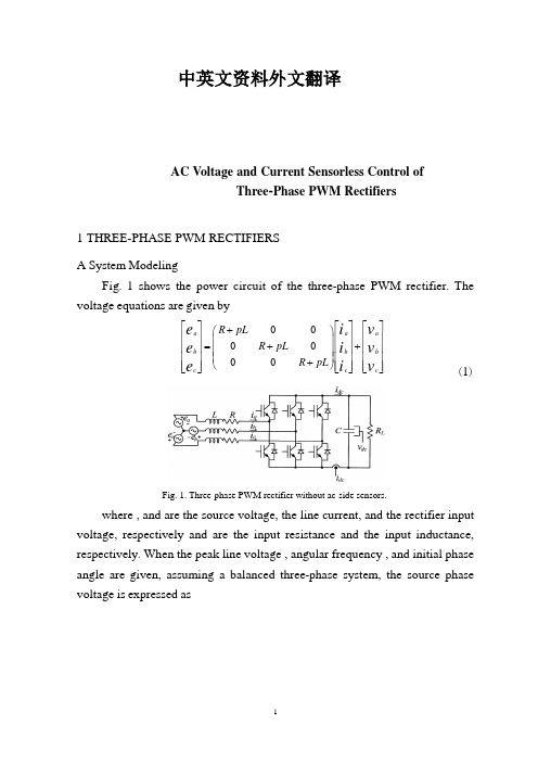
中英文资料外文翻译AC Voltage and Current Sensorless Control ofThree -Phase PWM Rectifiers1 THREE -PHASE PWM RECTIFIERSA System ModelingFig . 1 shows the power circuit of the three -phase PWM rectifier . The voltage equations are given by000000a a a b b b c c c R pL R pL R pL e i v e i v e i v ⎡⎤⎡⎤⎡⎤+⎛⎫⎢⎥⎢⎥⎢⎥ ⎪=++⎢⎥⎢⎥⎢⎥ ⎪⎢⎥⎢⎥⎢⎥ ⎪+⎝⎭⎢⎥⎢⎥⎢⎥⎣⎦⎣⎦⎣⎦ (1)Fig. 1. Three-phase PWM rectifier without ac-side sensors.where , and are the source voltage, the line current, and the rectifier input voltage, respectively and are the input resistance and the input inductance, respectively . When the peak line voltage , angular frequency , and initial phase angle are given, assuming a balanced three -phase system, the source phase voltage is expressed ascos 2cos()32cos()3a b c E e e e θθπθπ⎡⎤⎢⎥⎡⎤⎢⎥⎢⎥⎢⎥=-⎢⎥⎢⎥⎢⎥⎢⎥⎢⎥⎣⎦⎢⎥+⎣⎦ (2) Where0t θωθ=+ (3)A transformation matrix based on the estimated phase angle ,which transforms three -phase variables into a synchronous d –q reference frame, is23222cos cos()cos()323sin sin()sin()M M M M M M C θθπθπθθπθπ⎛⎫-+ ⎪ ⎪= ⎪++ ⎪⎝⎭ (4)Transforming (1) into the – reference frame using (4)qc qc qc M M dc dc dc e i v R pL L L R pL e i v ωω⎡⎤⎡⎤⎡⎤+-⎛⎫=+⎢⎥⎢⎥⎢⎥ ⎪+⎝⎭⎣⎦⎣⎦⎣⎦ (5)where p is a differential operator and .M M ωθ=Expressing (5) in a vector notationM e Ri LJi pLi v ω=+++ (6) where,qc dc e e e ⎡⎤=⎢⎥⎣⎦,qc dc i i i ⎡⎤=⎢⎥⎣⎦,qc dc v v v ⎡⎤=⎢⎥⎣⎦,0110J -⎛⎫= ⎪⎝⎭ (7) Taking a transformation of (2) by using (4)cos sin E e E θθ∆⎡⎤=⎢⎥∆⎣⎦ (8) WhereM θθθ∆=- (9)Expressing (6) and (8) in a discrete domain, by approximating the derivative term in (6) by a forward difference [9], respectively,[](1)(1)(1)()(1)(1)M e k Ri k LJi k L i k i k v k T ω-=-+-+--+- (10)c o s (1)(1)s i n (1)E k e k E k θθ∆-⎡⎤-=⎢⎥-∆-⎣⎦(11)Where T is the sampling period .Fig. 2. Overall control block diagram.B System ControlThe PI controllers are used to regulate the dc output voltage and the ac input current . For decoupling current control, the cross -coupling terms are compensated in a feed forward -typeand the source voltage is also compensated as a disturbance . For transient responses without overshoot, the anti -windup technique is employed [10]. The overall control block diagram eliminating the source voltage and line current sensors is shown in Fig . 2. The estimation algorithm of source voltages and line currents is described in the following sections .2 PREDICTIVE CURRENT ESTIMATIONThe currents of ()a I k and ()c I k can not be calculated instantly since the calculation time of the DSP is required . To eliminate the delay effect, a state observer can be used . In addition, the state observer provides the filtering effects for the estimated variable .Expressing (5) in a state -space form,x Ax Bu =+ (12) y Cx = (13) where,R L A R L ωω⎛⎫-- ⎪= ⎪ ⎪- ⎪⎝⎭,1010L B L ⎛⎫ ⎪= ⎪ ⎪ ⎪⎝⎭,1001C ⎛⎫= ⎪⎝⎭qc dc i x i ⎡⎤=⎢⎥⎣⎦,qc qc dc dc e v u e v -⎡⎤=⎢⎥-⎣⎦ And y is the output .Transforming (12) and (13) into a discrete domain, respectively,(1)()()X k FX k GU k +=+ (14)()()Y k HX k = (15)where,1111R T T L F R T T L ωω⎛⎫-- ⎪= ⎪ ⎪+- ⎪⎝⎭,00T L G T L ⎛⎫ ⎪= ⎪ ⎪ ⎪⎝⎭Then, the observer equation adding an error correction term to is given by(1)()()(()())X k F X k GU k K Y k Yk +=++- (16) Where K is the observer gain matrix and “^ ” means the estimated quantity, and (1)X k + is the state variable estimated ahead one sampling period . Subtracting (15) from (16), the error dynamic equation of the observer is expressed as(1)[]()rr rr e k F KC e k +=- (17) where ()()()rr e k X k X k =- . Here, it is assumed that the model parameters match well with the real ones . Fig . 3 shows the block diagram of the closed -loop state observer .The state variable error depends only on the initial error and is independent of the input . For (17) to converge to the zero state, the roots of the characteristic equation of (17) should be located within the unit circle .Fig. 3. Closed-loop state observer.Fig. 4. Short pulse region.4EXPERIMENTS AND DISCUSSIONSA. System Hardware ConfigurationFig. 5shows the system hardware configuration. The source voltage is a three-phase,110[V].The input resistance and inductance are0.06Ωand3.3 mH,respectively. The dc link capacitance is2350μF and the switching frequency of the PWM rectifier is3.5kHz.Fig. 5. System hardware configuration.Fig. 6. Dc link currents and corresponding phase currents (in sector V ).The TMS320C31DSP chip operating at33.3MHz is used as a main processor and two12-b A/D converters are used. One of them is dedicated for detecting the dc link current and the other is used for measuring the dc outputvoltage and the source voltages and currents,where ac side quantities are just measured for performance comparison.One of two internal timers in the DSP is employed to decide the PWM control period and the other is used to determine the dc link current interrupt. Considering the rectifier blanking time of3.5s,A/D conversion time of2.6s, and the other signal delay time,the minimum pulse width is set to10s.A.Experimental ResultsFig. 6shows measured dc link currents and phase currents. In case of sector V of the space vector diagram,the dc link current corresponds to for the switching state of and for that of . Fig. 7(a)shows the raw dc link current before filtering. It has a lot of ringing components due to the resonance of the leakage inductance and the snubber capacitor. When the dc current is sampled at the end point of the active voltage vectors as shown in the figure,the measuring error can be reduced.Fig. 7. Sampling of dc link currents.Fig. 8. Estimated source voltage and current at starting.To reduce this error further,the low pass filter should be employed,of which result is shown in Fig. 7(b). The cut-off frequency of the Butterworth’s second-order filter is112kHz and its delay time is about2sec. Since the ringing frequency is258kHz and the switching frequency is3.5[kHz],the filtered signal without significant delay is acquired.Fig. 8shows the estimated source voltage and current at starting. With the proposed initial estimation strategy,the starting operation is well performed. Fig. 9shows the phaseangle,magnitude,and waveform of the estimated source voltage,which coincide well with measured ones.Fig. 10shows the source voltage and current waveform at unity power factor. Figs. With the estimated quantities for the feedback control,the control performance is satisfactory. The dc voltage variation for load changes will be remarkably decreased if a feedforward control for theload current is added, which is possible without additional cur-rent sensor when the PWM rectifier is combined with the PWM inverter for ac motor drives.(a) phase angle (b)magnitude (c) waveform.Fig. 10. Source voltage and current waveforms.(a)estimated (b) measured.4 CONCLUSIONSThis paper proposed a novel control scheme of the PWM rectifiers without employing any ac input voltage and current sensors and with using dc voltage and current sensors only. Reducing the number of the sensors used decreases the system cost as well as improves the system reliability. The phase angle and the magnitude of the source voltage have been estimated bycontrolling the deviation between the rectifier current and its model current tobe zero. For line current reconstruction,switching states and measured dc link currents were used. To eliminate the effect of the calculation time delay of the microprocessor,the predictive state observer was used. It was shown that the estimation algorithm is robust to the parameter variation. The whole algorithm has been implemented for a proto-type1.5[kV A]PWM rectifier system controlled by TMS320C31DSP. The experimental results have verified that the proposed ac sensor elimination method is feasible.无交流电动势、电流传感器的三相PWM整流器控制1三相PWM整流器A 系统模型图一所示为三相PWM 整流器的主电路,电压等式给出如下:000000a a a b b b c c c R pL R pL R pL e i v e i v e i v ⎡⎤⎡⎤⎡⎤+⎛⎫⎢⎥⎢⎥⎢⎥ ⎪=++⎢⎥⎢⎥⎢⎥ ⎪⎢⎥⎢⎥⎢⎥ ⎪+⎝⎭⎢⎥⎢⎥⎢⎥⎣⎦⎣⎦⎣⎦ (1)图1 无交流传感器三相PWM 整流器其中e ,i 和v 分别是源电压,线电流和整流器的输入电压,R 和L 分别是输入电阻和输入电感。
外文翻译完整版
南京工程学院毕业设计外文资料翻译学生姓名:学号:班级名称:所在院系:Proceedings of the 6th Asia-Pacific Structural Engineering and Construction Conference (APSEC 2006), 5 – 6 September2006, Kuala Lumpur, Malaysia钢筋混凝土筒中筒结构高层建筑物的非线性有限元分析Abdul Kadir Marsono①I.ee Siong Wee②①马来西亚工艺大学结构与材料结构与材料系副教授②马来西亚工艺大学2004年土木工程学院研究生摘要非线性有限元分析作为一种简洁可靠的分析手段被经常用于土木结构的计算机分析技术。
在钢筋混凝土筒中筒高层建筑结构模型建立失败后,通过计算机应用程序提出了COSMOS/M。
采用三维模型方法进行研究是基于非线性材料,通过修改一个季度模型从而使得整体筒中筒高层建筑的双曲率精度大大提高。
钢筋混凝土结构的极限承载力决定了筒中筒高层建筑的混凝土开裂、压碎。
关键词非线性有限元;高层建筑;筒中筒结构1 引言筒中筒的概念在高层建筑中主要为了改善结构所能承受的横向阻力。
其基本形式包括一个中央核心筒,周边采用并列柱的框架结构,每层水平梁形成一个筒状结构。
通常这些对称的建筑物,其主要结构的变形发生在四个正交帧形成的周边筒和中央核心筒处(阿维格多鲁滕贝格和艾森伯格,1983)。
在水平荷载下的作用下,框架筒和中央核心筒像一个悬臂箱梁和二筒内的外筒。
为了得到更准确的分析结果,中央核心设计不但承担竖向重力负荷,还要抵御侧向荷载。
除楼板结构和内部筒一起作为一个单一的单位用于互动模式设计。
在本研究中被认为没有扭转效应,因此楼板是有效的连接于水平力垂直结构的建筑构件。
组合剪力墙和框架结构已被证明是一种能够加强高层建筑横向稳定的结构。
作为剪力墙剪力和弯矩的偏转,引起梁与板的轴向力偏转,周边框架和中央墙作为一个复合结构。
2019外研社高中英语选修一Unit 6 Nurturing Nature短语英汉互译表

强调...的重要性
58
由活珊瑚构成
59
60
遭受(...的)威胁
61
除...之外(还有,也)
62
谢天谢地
63
从...选...
64
许多...
65
担任
66
吸引人的营销
67
逐渐意识到…
68
渐渐明白…
69
梦想的旅游地
70
想出;认为
71
提高...的意识
7言为定;成交
74
涉及;有关
11
overcome challenge(s)
12
among the top concerns
13
catch one’s eye/attention
14
be about to do
15
at one’s leisure
16
allow ... to do sth.
17
speed past
18
seem unaware of…/that…
04
pass by
05
sit back in one’s seat
06
race along steadily
07
in one’s head
08
wind among the mountains
09
travel across the “roof of the world”
10
a record of...
28
protect... from...
29
reach out
30
bring ... to life
31
the Qinghai-Tibet Plateau
VICH GCP GL9中英对照

兽药临床试验管理规范GOOD CLINICAL PRACTICEVICH GL9Translated by Chen Jianzhao2017.08Guangzhou General Pharmaceutical Research Institute (GPRI)Guidance for IndustryGOOD CLINICAL PRACTICEVICH GL9FINAL GUIDANCE(This document was revised on June 8, 2011 to update the contact information, add the Table of Contents, update hyperlinks, and minor formatting changes)This final guidance is intended to provide guidance on the design and conduct of all clinical studies of veterinary medicinal products in the target species submitted for approval to the European Union, Japan, and the United States.Comments and suggestions regarding this guidance should be sent to the Division of Dockets Management (HFA-305), Food and Drug Administration, 5630 Fishers Lane, Room 1061, Rockville, MD 20852. Comments may also be submitted electronically on the Internet at . All written comments should be identified with Docket No 99D-2406.For questions regarding this guidance document, contact Herman M. Schoenemann (HFV-100), Center for Veterinary Medicine, Food and Drug Administration, 7500 Standish Pl., Rockville, MD 20855, 240-276-8302, e-mail: herman.schoenemann@.U.S. Department of Health and Human Services Food and Drug Administration Center for Veterinary MedicineMay 9, 2001Final GuidanceINTRODUCTION1. GLOSSARY1.1. Adverse Event (AE)1.2. Applicable Regulatory Requirement(s)1.3. Audit1.4. Authenticated Copy 行业指南兽药临床试验管理规范VICH GL9最终指导(本文件于2011年6月8日修订,更新联系信息,添加目录,更新超链接和次要格式更改)本指南旨在为提交给欧盟,日本和美国的目标物种的兽药产品的所有临床研究的设计和实施提供指导。
外文翻译中文译文(附英文原文)
对由ansys开发的大型工程模型的降阶Evgenii B. Rudnyi 和 Jan G. KorvinkIMTEK微控技术研究所弗赖堡大学Georges-K ohler-Allee,103D - 79110,德国弗赖堡{ rudnyi,korvink } @imtek.dehttp://www.imtek.uni-freiburg.de/simulation/摘要工程师能够在ANSYS开发的有限元模型中运用现有的软件实现现代模型降阶技术。
我们着于一个人如何独立的从在ANSYS和C ++上实现的执行模型中提取所需的信息,而不用依靠特别的专业人士,我们将利用与结构力学和热力学有限元模型相关的实例来讨论计算成本。
1.介绍大型线性动态系统模型降阶已经是相当成熟的领域[1]。
许多论文(见参考文献[2])指出,模型降价的优势已在各种科学和工程应用上被证实。
我们目前的工作是集中讨论工程师如何将该技术与现有的商业有限元软件相结合,以达到如下目的:—加快对瞬变电压、谐波的分析;—自动生成系统级仿真的紧凑模型;—在设计阶段纳入有限元程序包。
通常大规模动态系统模型降阶第一步如下Ex˙=Ax+Bu (1.1)y=Cx其中A和E是系统矩阵,B是输入矩阵,C是输出矩阵。
模型降阶的目的是产生一个低维式以逼近(1.1),Erz=Arz.+BruY=Crz. (1.2)此式描述了输入向量u对输出向量y的依赖,因此,同一时间降阶后向量z的维数远小于原来x的状态向量维数。
对由偏微分描述的用户模型方程进行空间离散化后,有限元程序包通常产生一个常微分方程系统。
在这阶段,它有可能直接适用于模型降阶的方法[1]。
然而,从商业包装过的系统矩阵里提取却不是这样,我们将介绍我们是怎么用ANSYS有限元分析做到的[3]。
我们选择了市场矩阵形式来表示简化模型(1.2)[4]。
我们假设在另一个包如Matlab或Mathematica 上完成其仿真。
降价模型在数学方面的运作是可行的,这可以参见http://www.imtek.unifreiburg.de/ simulation/mathematica/IMSweb/非线性系统矩阵的维数高并且可降阶。
- 1、下载文档前请自行甄别文档内容的完整性,平台不提供额外的编辑、内容补充、找答案等附加服务。
- 2、"仅部分预览"的文档,不可在线预览部分如存在完整性等问题,可反馈申请退款(可完整预览的文档不适用该条件!)。
- 3、如文档侵犯您的权益,请联系客服反馈,我们会尽快为您处理(人工客服工作时间:9:00-18:30)。
温度单向输入系统增益调整模糊控制器Shiuh-jer huang and chen-chuan wang1,台北国立科技大学,车辆工程部,台湾省台北市106号,chung-hsiao 东路1号。
2,台湾国立科技大学,机械工程部,台湾省台北市106号,keelung路43号。
在很多化工和半导体制造过程中,温度是控制所需产品质量的重要参数。
一般来说,温度控制系统具有响应速度慢,时滞,和单向控制输入特性等非线性的时变特征。
很难估计出准确的动力学模型和设计出一种能够取得良好的控制特性的温度控制器。
在这里提出了一种针对密闭铁腔单向加热输入控制器的无模型智能模糊增益调整控制策略。
这个概念在控制过程中被用来调整增益调度的模拟隶属函数映射的适用范围从而改善控制性能。
实验表明该控制方案无超调,并且稳态误差的阶跃输入响应总小于0.28℃。
该方案适用于工业温度控制系统。
关键词:模糊控制温度控制和增益调度单向输入1简介在化学,材料,半导体制造过程中,温度是一个重要的控制参数。
例如:退火,薄膜材料玻璃熔化炉沉积和电视都需要适当的温度控制系统。
一些温度控制系统具有加热和冷却控制阶段,而其他系统只有加热输入控制阶段。
他们的动态特性有着显著差异。
加热器输入的温度控制系统比有两个阶段的控制系统更难以取得良好的控制效果。
如何设计一种具有响应速度快,稳态误差小,无超调的特点的通用温度控制器在工业实施控制研究领域仍然是一种挑战。
目前,开关控制和PID控制方案用于商业产品。
在1936年,一种PID控制器被设计出来。
目前,PID控制器已经广泛应用于工业自动化的控制系统。
然而,如何调整控制增益因素是实施PID控制器的关键。
如果精确的动态模型对于控制系统是有效的,nichols和ziegler规则(nichols和ziegler,1942年),和IMC控制策略(chien和fruehauf,1990;rivera等人1986年)可以计算出适当的收益。
然而,供热厂有延时和温度依赖的非线性特性。
对于一个PID控制器的设计很难建立精确的动态模型。
一般来说,系统需要一个实验的过程来获得好的控制响应。
当该系统具有外部干扰或设定值发生变化时,其瞬态响应也会变坏。
这样的系统需要一个网络在线的工作人员来调整它或者切换到手动控制。
然而这是一个不方便的应用,而且生产参数可能不保持在一个良好的成产水平上。
因此,无模型智能控制方案已经得到了关注。
基于控制水浴加热温度提出了一种自整定PID控制策略(Yusof 等人,1994年)。
采用频率loop-shaping技术来调整PID温度控制器的增益的一种化学气相沉积(CVD)扩散炉(Grassi和Tsakalis,2000年)。
这种方法的适当的收益是搜查了基于系统输出响应的一个开关开路继电器控制。
此外,采用模糊控制技术以其自身的智能特性已成功应用在许多工业过程,。
最近,模糊控制理论用来提高PID控制器的自适应性和鲁棒性。
提出了一种基于混合模糊控制和PI控制的为电视玻璃熔化炉温度控制的方法(Moon 和 Lee,2000,2003)。
采用模糊逻辑方案也适用于调整PID控制器收益(陈和李,2003;He等,1993;Visioli高庆宇,2001)。
这些方法与传统的PID的收获是非线性函数的跟踪控制的性能。
他们可以在输出误差的基础上自动调节。
与传统的PID控制器相比可以达到较好的鲁棒性,快速反应和更小的超调。
然而,很难设计一个通用的模糊控制规则表和相应的模糊参数。
因此,一种自组织模糊控制器(鲁和陈,1994)和自适应模糊控制方案(Haissig,1999)被用与设计温度控制器以获得稳定的性能,但这些控制策略仍不能达成一个快速和精确的瞬态响应稳态响应。
通常,温度控制系统具有非线性时变、时滞特征。
很难估计一个基于适当的动态模型的控制器的设计。
特别是,温度控制问题单向加热器输入只有滞后、不对称控制行为。
基于传统控制算法的反应很难实现精确的温度控制精度有较好的瞬态。
这里以无模型增益调整为研究对象,运用模糊控制方案设计一个加热器输入单相温度控制器与模糊增益参数,自动控制,可获得较好的瞬态响应和很小的稳态误差的通用的智能温度所设计的控制器是本文的目的。
温度动态响应模糊控制器的性能将增益调整相比,自整定PID控制器。
实验试验台是一个空洞的金属腔只具有加热器控制输入。
2,系统结构基于pc机的控制系统的温度监测系统的结构如图1所示。
PC发送的控制电压通过D / A卡输入到SCR驱动器。
一个12-bit低成本ASIO-113 AD / DA / 8255板卡确定为本控制系统。
SCR驱动器250欧姆的内阻控制电压转换成1 - 5 V 4 - 20毫安的控制输入电流的供暖棒。
这个SCR可以监视输出功率单相110-V和20-A 替代目前的电源。
它调节电流输入电棒加热提高温度空心金属腔。
介质内部的空洞圆柱腔体的空气。
中空的温度测量金属筒用一个电阻温度传感器(RTD)和通过A / D转换卡反馈到PC。
温度控制算法实现Cþþ程序。
一个空心金属腔实验试验台是建立评价控制性能。
铁的尺寸是250毫米空心圆柱在高度和51毫米直径空心孔直径与10-mm设立电棒加热温度传感器和RTD PT100。
选择PT100 RTS传感器是由于0.28C 3008C温度测量范围内的准确性。
RTD传感器的敏感性是0.0015每摄氏度。
取样频率以下的实验设置为40赫兹。
3,自整定PID控制ad K u 4影响因素控制系统性能的PID 控制关键是怎么才能找到最佳的配置比例增益、积分时间常数和导数时间常数。
为切实实施,这些增益的调整,实现了一项专长或一位经验丰富的工程师,试误修改。
这是耗时的工作过程并且动态响应的行为不能得到保证。
为此, 电反馈评价方法,提出了一种基于发现的增益参数的PID 控制器 (Astrom 和Hagglund,1984年)。
首先,一个开关切换控制应用于前2个周期。
当系统温度低于设定值,控制器完全打开来驱动温度。
当温度达到调定值,控制输入立即切断。
然后临界增益,Ku,和关键的时期,Pu,可以发现从这些输入输出响应曲线就像图2,(1)因此,这个增益参数可以采用计算公式的Ziegler-Nichols 经验丰富。
and P T K k u i u p ,2,6.0==8u d P T=uP K K 6.0=iP i T K K =anddP d T K K =(2)那意味着(3)这些PID 控制增益可以用来监视系统温度的阶跃变化。
4,增益调整模糊逻辑控制器因为这个温度控制系统具有明显的滞后、单向输入非线性行为,很难建立一个适当的动态模型精确模型控制器的设计。
此外,超瞬态温度控制系统的响应,与时滞和单相供暖输入动态特征,这很难以避免和快速消除。
因此,如何设计一个通用的温度控制器与小超调,快速反应将是一场具有挑战的研究课题。
这里的无模型增益调整提出了一种模糊控制策略来解决这个问题。
控制框图如图3。
通常一个模糊方法的动机是,认识不够和动态模型具有不确定性。
采用模糊集理论来模拟逻辑推理的人类。
主要的组成部分,是一组模糊控制器语言的模糊控制规则和推理引擎要解释这些规则。
这些模糊规则之间提供一个转型的语言知识控制一个专家,自动控制策略的一种催化剂。
每一个模糊控制规则组成的先例和一系列的;一般形式的规则可以被表示为1R :IF X is 1A and Y is 2A ,THEN U is 1C (4)这里Ri是电流规则,X和Y是系统被控输出的声明而U是系统输入的声明。
A1,A2和C1分别是相应输入输出的模糊子集。
每个输出的模糊规则的重要性取决于隶属函数的语言输入和输出变量。
该控制系统,有两个输入的指标模糊控制器的温度误差和误差变化的ce,e和输出指标是控制电压u。
为了简化计算的模糊控制器,七平等的跨度三角形隶属度函数用遗传算法对模糊控制器输入变量e和ce。
他们是NB,NM,NS,ZO,PS,PM和PB。
这些的隶属函数的模糊变量如图4所示。
这个隶属度函数的规模通过改变尺度参数的隶属度函数可扩展或缩小。
增益参数是用于映射相应的变量转化该标称的范围。
在人类的直觉,当温度误差大,控制电压应增加,以满足更多能量用来加热温度控制腔和减少误差。
在另一方面,当误差趋近于零的子集的隶属度函数,控制器应微调改正应提供的小小变化温度误差和减少超调现象的倾向。
这两种情况可以通过分离隶属函数和一个增益参数去掉。
这些映射参数指定以ge,gce和gu分别对应误差、误差变化及控制电压,分别列在表1。
表1 模糊增益比例因数参数ge和gce是指定比例因子模糊输入变量分别对应操作温度范围的误差和误差变化。
该参数gu的设计是一个增益调整模糊逻辑控制电压和实验再调整努力简化为设计模糊规则表。
这个方法是一个新的增益调整模糊控制结构。
这些参数值为这个增益调整非临界的模糊逻辑控制器。
他们可以通过简单的实验大致可以确定。
然后有相同的价值观可以应用到不同的温度设定分阶跃响应控制与适当的稳态精度。
为该温控系统、ge = 5 和 gce = 2用于粗调,而ge = 2 and gce = 1 用于微调任何不同的温度设定点。
相应的模糊隶属度函数的控制误差覆盖的温度范围分别对应68摄氏度粗调和2.48摄氏度的微调,如图5所示。
该控制器软件的程序可以自动开关的粗调和微调控制范围之间的温度数据,通过误差反馈信号。
控制获得其价值gu取决于温度设定点的因环境因素引起的热量平衡的问题。
它需要一个小实验获得其价值为某个特定的温度范围内设置,例如50-808C,80-1208C,120-1508C等等。
这些参数值并不是至关重要。
每个增益参数在一定范围内可达到合理的动态反应。
否则,我们需要设计一个不同的模糊控制规则表为每个温度设定范围。
那将是一个花费更多的时间和繁琐的工作比所建议的方法。
在这项研究中,整个论述中的隶属度函数分为两个区域,微调和粗调地区。
图5给出了两组不同的隶属度函数的个别跨度。
在温度的阶跃响应开始的时候,该控制器能在回应大错误的区域中自动选择一个大的范围(粗调划分区域)。
当温度达到稳定状态,控制器将开关覆盖范围的隶属函数,进了微调区域来纠正稳态误差。
该控制策略能开关自动之间的不同控制范围和分裂的隶属度函数,在一种基于反馈的信号控制变量的误差、e和ce只通过改变增益比例因子的隶属度函数改变。
除此之外,系统热量平衡控制电压也包括在这个用来代替这个额外的价值偏移控制其他控制算法,简化了控制器的设计问题和控制律法计算而设计的模糊规则表中。
表2 加热器模糊规则表)(1)(w a x w x +--=μ∑∑=ii i y y ωω∏=jjij ix A )(μω在本文中,49模糊规则是被用于控制利用用SCR 输入电压校正腔的温度。