MTU 柴油机20V_4000_R43技术规范(英文)
MTU柴油机16V4000G83_60Hz_Kd_D

60 Hz - 1.800/minKraftstoffverbrauchsoptimiertArbeitsverfahrenViertakt-Diesel Schwungradgehäuse SAE 00Verbrennungsverfahren DirekteinspritzungSchwungrad21AufladesystemZähnezahl Schwungrad 182Einspritz-SystemBohrung / Hub 170 / 210 mm Hubraum, gesamt 76.3 Liter Anzahl Zylinder 16Regelung / Überwachung ZylinderanordnungV - 90°Anzahl Abgasturbolader 4Verdichtungsverhältnis 16.5 : 1Anzahl Ladeluftkühler1Drehrichtunglinks(auf Schwungradseite gesehen)MTU-Anwendungsgruppe3D 3B (ICFN)(ICXN)MotorleistungkW A 25002280Mittlere Kolbengeschwindigkeit m/s A 12.612.6Mittlerer effektiver Druckbar A 21.919.9Gewicht ( Motor in Basisausführung)trocken kg R 77007700nass kg R --Abmessungen (nur Motor)Länge mm R 30013001Höhe mm R 16601660BreitemmR21542154VerbrauchSpezifischer Kraftstoffverbrauch 100% Last g/kWh G 209202(Toleranz +5% entspr. ISO 3046/1) 75% Last g/kWh R 19820050% Last g/kWhR 207209Schmierölverbrauch (nach Motoreinlauf)R 0.30.3FüllmengenSchmieröl (bei Standardölsystem)gesamtLiter R 300300Peilstabmarke min..Liter L 210210Peilstabmarke max.Liter L 240240Motorkühlmittelkreislauf Liter R 175175LadeluftkühlmittelkreislaufLiter R 5050Abzuführende Wärmemengen Motorkühlmittelkreislauf 100% Leistung kW R 960840Ladeluftkühlmittelkreislauf 100% Leistung kW R 660560Strahlungs- und Konvektionswärme kW R 9090AnlaßsystemElektrischer Anlasser (Fabr. Delco)Spannung V R 2424LeistungkW R --Stromaufnahme max.A R --Stromaufnahme bei Zünddrehzahl AR --Empfohlene Batteriekapazität Blei Ah/20h R 450450 NiCd Ah/5hR 240240Zünddrehzahl1/min R 80 - 12080 - 120KühlmittelvorwärmungVorwärmtemperatur, minimum °C R 3232HeizleistungkW R 99Änderungen im Interesse des technischen Fortschrittes vorbehaltenSeite 1Stand:Common Rail"-System mit elektronisch gesteuerter Hochdruckeinspritzung über EinzeleinspritzpumpenElektronischesMotormanagementsystem "ADEC"Abgasturboaufladung und Wasser-Ladeluftkühlung (extern);Oktober 200760 Hz - 1.800/minKraftstoffverbrauchsoptimiertMTU-Anwendungsgruppe3D3B(ICFN)(ICXN)Kühlsystem-MotorkühlmittelkreislaufKühlmitteltemperatur Motoraustritt ( zum Kühler)°C A100100Kühlmitteltemperatur nach Motor Warnung°C R102102Kühlmitteltemperatur nach Motor Abstellung°C L104104 Gefrierschutzmittelanteil im Kühlmittel max. zulässig%L5050Kühlanlage : Kühlmittel-Volumenstrom m3/h A8181Kühlmittelpumpe : Eingangsdruck, min.bar L0.20.2Kühlmittelpumpe : Eingangsdruck, max.bar L 1.5 1.5 Druckverlust im motor-externen Kühlsystem, max. zul.bar L0.70.7Kühlanlage : Höhe über Motorniveau, max. zulässig m L1515Kühlanlage : Auslegungsbetriebsdruck, max. zulässig bar A 2.5 2.5Kühlsystem-LadeluftkühlmittelkreislaufKühlmitteltemperatur : Eintritt in Ladeluftkühler°C A5555 Gefrierschutzmittelanteil im Kühlmittel max. zulässig%L5050Kühlanlage : Kühlmittel-Volumenstrom m3/h A3535 Druckverlust im motor-externen Kühlsystem, max. zul.bar L0.70.7Kühlanlage : Höhe über Motorniveau, max. zulässig m L1515Kühlanlage : Auslegungsbetriebsdruck, max. zulässig bar A 2.5 2.5AnsaugluftsystemVolumenstrom Ansaugluft m³/s R 3.2 3.1 Ansaugunterdruck neue Luftfilter mbar A1515verschmutzte Luftfilter mbar L5050KraftstoffsystemKraftstoffmenge Motorzulauf (max)l/min R1717Maximale Zulauftemperatur °C L5555Max Überdruck vor Kraftstoffförderpumpe bar L 1.5 1.5Max Unterdruck vor Kraftstoffförderpumpe bar L-0.1-0.1AbgassystemAbgasmenge m³/s R8.47.6 Abgastemperatur nach Turbolader°C R505465 Abgasgegendruck max. zulässig mbar L8585Allgemeine BetriebsdatenEmpfohlene Mindestdauerbelastung%R2020Trägheitsmoment, Motor mit Schwungrad kgm²R23.123.1Schallemission(Freifeldschalldruckpegel, 1m Meßabstand)Motoroberflächengeräusch dB(A)R107106Ungedämpftes Abgasgeräusch dB(A)R118116A = Auslegungswert; G = Garantiwert; R = RichtwertL = Grenzwert, bis zu dem volle Motorleistung zur Verfügung steht Bezugsbedingungen für Motorleistung:- = Daten nicht verfügbar; * = Geschätzter oder hochgerechneter WertStandard Leistungen verfügbar bisAnsauglufttemperatur:25°C40°CAufstellhöhe über NN:100 m400 mMTU Friedrichshafen GmbHMaybachplatz 188045 Friedrichshafen/GermanyTelefon: (07541) 90 70 60Telefax: (07541) 90 70 84E-Mail: powergen@Internet: Änderungen im Interesse des technischen Fortschrittes vorbehalten Seite 2Stand:Oktober 2007。
MTU柴油机资料12V4000G433Bdeconsumption
Technische Verkaufsunterlage Ausdruck vom: (J-M-T) 2007-12-13
- MOTORDATEN -
MTU Projekt-Nr.
Nr.
Anwendungsgruppe MTU-Datenkennziffer Ansauglufttemperatur Ladeluftkühlmitteltemperatur Luftdruck Einsatzhöhe über NN Fremdwassereintrittstemperatur
X
6 Anzahl der Zylinder
12
7 Zylinderanordnung: V-Winkel
ห้องสมุดไป่ตู้
Grad
90
10 Bohrung
mm
170
11 Hub
mm
210
12 Hubraum eines Zylinders
Liter
4.77
13 Gesamthubraum
Liter
57.2
14 Verdichtungsverhältnis
R g/kWh
201
73 Kraftstoffverbrauch bei Nullast
R kg/h
29.0
61
Schmierölverbrauch nach 100h Laufzeit (B = stündlicher Kraftstoffverbrauch)
R % von B
0.3
62
Schmierölverbrauch nach 100h Laufzeit, max. (B = stündlicher Kraftstoffverbrauch)
16v4000g43s技术参数
16v4000g43s技术参数
16V4000G43S是MTU(MTU Friedrichshafen GmbH)推出的一款柴油发动机,常用于船舶、发电机组以及工业应用中。
以下是该发动机的一些技术参数:
1. 缸数,16。
2. 排量,65.6升。
3. 最大功率,约2330千瓦(3100马力)。
4. 最大扭矩,约15000牛顿米。
5. 燃油消耗,取决于负载和运行条件。
6. 排放标准,符合国际尾气排放标准。
16V4000G43S采用先进的柴油机技术,具有高功率和高效率的特点。
它还采用了先进的排放控制技术,以满足严格的环保标准。
该发动机可靠性高,维护成本低,广泛应用于需要大功率输出和长
时间运行的领域。
总的来说,16V4000G43S是一款强大而可靠的柴油发动机,适用于各种工业应用和特殊环境下的动力需求。
MTU柴油发电机组使用说明书
柴油发电机组使用说明书前言本技术使用维护手册是为用户提供安装、使用、保养与操作方法的通用性手册。
利用本手册需结合柴油机、交流发电机与控制箱厂家提供的使用维护手册参照使用,以确保发电机组能长期地提高效率运作。
操作与维护应由经过专业训练的人员进行,机组使用前应仔细阅读本手册,在对柴油发电机组有正确认识了解后方可操作使用。
随着产品的不断改进,本手册所涉及的内容也会相应增补与修改,请用户注意。
1 安全1.1. 安全警告本机组在设计和制造过程中充分考虑了安全因素和对人身健康的影响。
使用者在使用前必须认真阅读以下内容,并在操作过程中严格地遵守本手册规定的制度,以避免事故发生。
因不可能预计所有使用之环境,因此本手册所列举之事项亦非万全,请用户结合本单位实际在使用过程中适当增减规定条款。
凡因违章引起的安全事故和人身健康损伤,本公司概不负责。
!发动机启动前,所有的保护装置,特别是冷却风扇保护罩必须正确牢固安装。
!在运转前,所有的电器应检查是否联结牢固。
!应保证所有地线接地良好可靠。
!所有可以锁定的门和盖板在运转前应固定。
!保养维护时,可能涉及到重型零件或危及生命的电气设备。
因此,操作者必须经过适当的培训,不要独自操作设备,以防万一发生意外时有人帮助处理。
!如对设备内部进行清洁或修理,请将蓄电池负极线拆下,并贴上警示标记,以防发动机意外启动,引起人身伤害。
1.2. 保护罩机组设有对运转零件保护的保护罩。
开机时在机组旁工作的人员必须小心注意各活动机械部分可能对人身产生的危险。
!在风扇或其他保护罩拆开的情况下,切勿试图开机。
机组运转时,切勿试图将手伸入机组运转部位。
!机组工作时,要穿上工作服,防止宽松衣服、手、长头发等绞入转动部位,防止油、水、气和机身烫伤人体。
!不要在冷却液未完全冷却时拧开散热器盖。
待冷却液冷却后,先拧松盖子,让里面的气体先行释放,然后才能把盖拧开。
!机组运行时,应将所有罩、盖与门板装妥,以免发生事故。
MTU柴油机资料12V4000G23_3D_en_consumption

R = Guideline value
MTU Friedrichshafen
Technical Sales Documentation
Sheet 2 of 9
________________________________________________________________________________________________________________________
MTU Project No.
°C °C mbar m °C
18
--
37
--
33
--
25
--
8 12 13
--X
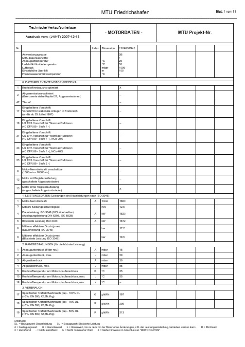
Explanation: CP = Ref.value: Continuous power FSP = Ref.value: Fuel stop power A = Design value G = Guaranteed value L = Limit value, up to which the engine can be operated, without change (e.g. of power setting) X = Applicable - = Not applicable N = Not yet defined value Z = See notes provided after "ENGINE DATA"
- ENGINE DATA Printout: (y-m-d) 2007-12-13
No. Application Group MTU data code Intake air temperature Charge-air coolant temperature Barometric pressure Site altitude above sea level Raw-water inlet temperature 0. DATA-RELEVANT ENGINE DESIGN CONFIGURATION 1 2 47 17 Fuel-consumption optimized Exhaust-emissions optimized (limit values see Exhaust Emissions, Chapter 21) "TA-Luft" (German clean-air standard) Complies with: Regulations for stationary power plants in France (arrêté du 25 Juillet 1997) Complies with: US EPA, regulation for nonroad engines (40 CFR 89 - Tier 1 -) Complies with: US EPA regulations for nonroad engines (40 CFR 89 - Tier 1 -) NOx-20% Complies with: US EPA regulations for nonroad engines (40 CFR 89 - Tier 1 -) NOx-40% Complies with: US EPA, regulation for nonroad engines (40 CFR 89 - Tier 2 -) Engine rated speed switchable (1500/1800 rpm) Engine with sequential turbocharging (turbochargers with cut-in/cut-out control) Engine without sequential turbocharging (turbochargers without cut-in/cut-out control) 1. POWER-RELATED DATA (power ratings are net brake power to ISO 3046) 1 3 5 9 Engine rated speed Mean piston speed Fuel stop power ISO 3046 Mean effective pressure (MEP) (Fuel stop power ISO 3046) 2. GENERAL CONDITIONS (for maximum power) 1 2 3 4 5 10 18 Intake air depression (new filter) Intake air depression, max. Exhaust back pressure Exhaust back pressure, max. Fuel temperature at fuel feed connection Fuel temperature at fuel feed connection, max. Fuel temperature at fuel feed connection, min. 3. CONSUMPTION 56 57 58 59 73 Specific fuel consumption (be) - 100 % FSP (+ 5 %; EN 590; 42.8 MJ/kg) Specific fuel consumption (be) - 75 % FSP (+ 5 %; EN 590; 42.8 MJ/kg) Specific fuel consumption (be) - 50 % FSP (+ 5 %; EN 590; 42.8 MJ/kg) Specific fuel consumption (be) - 25 % FSP (+ 5 %; EN 590; 42.8 MJ/kg) No-load fuel consumption G R R R R g/kWh g/kWh g/kWh g/kWh kg/h 189 194 200 228 21.0 A L A L R L L mbar mbar mbar mbar °C °C °C 15 50 30 85 25 55 -A A rpm m/s kW bar 1500 10.5 1575 22.0 X ---Index Unit 12V4000G23 3D 1 25 55 1000 100 -
MTU柴油机20V4000G83L_60Hz_Ad_epa1_2_D

60 Hz - 1.800/minAbgasoptimiert (EPA Stufe 1 und EPA Stufe 2)ArbeitsverfahrenViertakt-Diesel Schwungradgehäuse SAE 00Verbrennungsverfahren DirekteinspritzungSchwungrad21AufladesystemZähnezahl Schwungrad 182Einspritz-SystemBohrung / Hub 170 / 210 mm Hubraum, gesamt 95.4 Liter Anzahl Zylinder 20Regelung / Überwachung ZylinderanordnungV - 90°Anzahl Abgasturbolader 2Verdichtungsverhältnis 16.5 : 1Anzahl Ladeluftkühler1Drehrichtunglinks(auf Schwungradseite gesehen)MTU-Anwendungsgruppe3D 3B (ICFN)(ICXN)MotorleistungkW A 34903010Mittlere Kolbengeschwindigkeit m/s A 12.612.6Mittlerer effektiver Druckbar A 24.421.0Gewicht ( Motor in Basisausführung)trocken kg R 96409640nass kg R --Abmessungen (nur Motor)Länge mm R 35123512Höhe mm R 16131613BreitemmR24812481VerbrauchSpezifischer Kraftstoffverbrauch 100% Last g/kWh G 219214(Toleranz +5% entspr. ISO 3046/1) 75% Last g/kWh R 209*212*50% Last g/kWhR 218*221*Schmierölverbrauch (nach Motoreinlauf)R 0,30,3FüllmengenSchmieröl (bei Standardölsystem)gesamtLiter R 390*390*Peilstabmarke min..Liter L 245*245*Peilstabmarke max.Liter L 340*340*Motorkühlmittelkreislauf Liter R 205*205*LadeluftkühlmittelkreislaufLiter R 55*55*Abzuführende Wärmemengen Motorkühlmittelkreislauf 100% Leistung kW R 13901130Ladeluftkühlmittelkreislauf 100% Leistung kW R 1010820Strahlungs- und Konvektionswärme kW R 105105AnlaßsystemElektrischer Anlasser (Fabr. Delco)Spannung V R 2424LeistungkW R --Stromaufnahme max.A R --Stromaufnahme bei Zünddrehzahl AR --Empfohlene Batteriekapazität Blei Ah/20h R 450450 NiCd Ah/5hR 240240Zünddrehzahl1/min R 80 - 12080 - 120KühlmittelvorwärmungVorwärmtemperatur, minimum °C R 3232HeizleistungkW R 99Änderungen im Interesse des technischen Fortschrittes vorbehaltenSeite 1Stand:Common Rail"-System mit elektronisch gesteuerter Hochdruckeinspritzung über EinzeleinspritzpumpenElektronischesMotormanagementsystem "ADEC"Abgasturboaufladung und Wasser-Ladeluftkühlung (extern);Oktober 200760 Hz - 1.800/minAbgasoptimiert (EPA Stufe 1 und EPA Stufe 2)MTU-Anwendungsgruppe3D3B(ICFN)(ICXN)Kühlsystem-MotorkühlmittelkreislaufKühlmitteltemperatur Motoraustritt ( zum Kühler)°C A100100Kühlmitteltemperatur nach Motor Warnung°C R102102Kühlmitteltemperatur nach Motor Abstellung°C L104104 Gefrierschutzmittelanteil im Kühlmittel max. zulässig%L5050Kühlanlage : Kühlmittel-Volumenstrom m3/h A100100Kühlmittelpumpe : Eingangsdruck, min.bar L0.50.5Kühlmittelpumpe : Eingangsdruck, max.bar L 1.5 1.5 Druckverlust im motor-externen Kühlsystem, max. zul.bar L0.70.7Kühlanlage : Höhe über Motorniveau, max. zulässig m L1515Kühlanlage : Auslegungsbetriebsdruck, max. zulässig bar A 2.5 2.5Kühlsystem-LadeluftkühlmittelkreislaufKühlmitteltemperatur : Eintritt in Ladeluftkühler°C A4545 Gefrierschutzmittelanteil im Kühlmittel max. zulässig%L5050Kühlanlage : Kühlmittel-Volumenstrom m3/h A3737 Druckverlust im motor-externen Kühlsystem, max. zul.bar L0.70.7Kühlanlage : Höhe über Motorniveau, max. zulässig m L1515Kühlanlage : Auslegungsbetriebsdruck, max. zulässig bar A 2.5 2.5AnsaugluftsystemVolumenstrom Ansaugluft m³/s R 4.5 4.3 Ansaugunterdruck neue Luftfilter mbar A1515verschmutzte Luftfilter mbar L5050KraftstoffsystemKraftstoffmenge Motorzulauf (max)l/min R2222Maximale Zulauftemperatur °C L5555Max Überdruck vor Kraftstoffförderpumpe bar L 1.5 1.5Max Unterdruck vor Kraftstoffförderpumpe bar L-0.1-0.1AbgassystemAbgasmenge m³/s R12.310.8 Abgastemperatur nach Turbolader°C R545485 Abgasgegendruck max. zulässig mbar L8585Allgemeine BetriebsdatenEmpfohlene Mindestdauerbelastung%R2020Trägheitsmoment, Motor mit Schwungrad kgm²R34.6734.67Schallemission(Freifeldschalldruckpegel, 1m Meßabstand)Motoroberflächengeräusch dB(A)R114112Ungedämpftes Abgasgeräusch dB(A)R124123A = Auslegungswert; G = Garantiwert; R = RichtwertL = Grenzwert, bis zu dem volle Motorleistung zur Verfügung steht Bezugsbedingungen für Motorleistung:- = Daten nicht verfügbar; * = Geschätzter oder hochgerechneter WertStandard Leistungen verfügbar bisAnsauglufttemperatur:25°C40°CAufstellhöhe über NN:100 m400 mMTU Friedrichshafen GmbHMaybachplatz 188045 Friedrichshafen/GermanyTelefon: (07541) 90 70 60Telefax: (07541) 90 70 84E-Mail: powergen@Internet: Änderungen im Interesse des technischen Fortschrittes vorbehalten Seite 2Stand:Oktober 2007。
MTU柴油机20V4000G23_50Hz_Ad_D

50 Hz - 1.500/minAbgasoptimiert (TA-Luft)ArbeitsverfahrenViertakt-Diesel Schwungradgehäuse SAE 00Verbrennungsverfahren DirekteinspritzungSchwungrad21AufladesystemZähnezahl Schwungrad 182Einspritz-SystemBohrung / Hub 170 / 210 mm Hubraum, gesamt 95.4 Liter Anzahl Zylinder 20Regelung / Überwachung ZylinderanordnungV - 90°Anzahl Abgasturbolader 2Verdichtungsverhältnis 16.5 : 1Anzahl Ladeluftkühler1Drehrichtunglinks(auf Schwungradseite gesehen)MTU-Anwendungsgruppe3D 3B (ICFN)(ICXN)MotorleistungkW A -2200Mittlere Kolbengeschwindigkeit m/s A -10.5Mittlerer effektiver Druckbar A -18.5Gewicht ( Motor in Basisausführung)trocken kg R -9640nass kg R --Abmessungen (nur Motor)Länge mm R -3512Höhe mm R -1613BreitemmR-2481VerbrauchSpezifischer Kraftstoffverbrauch 100% Last g/kWh G -213(Toleranz +5% entspr. ISO 3046/1) 75% Last g/kWh R -21350% Last g/kWhR -217Schmierölverbrauch (nach Motoreinlauf)R -0,3FüllmengenSchmieröl (bei Standardölsystem)gesamtLiter R -390*Peilstabmarke min..Liter L -245*Peilstabmarke max.Liter L -340*Motorkühlmittelkreislauf Liter R -205*LadeluftkühlmittelkreislaufLiter R -55*Abzuführende Wärmemengen Motorkühlmittelkreislauf 100% Leistung kW R -920Ladeluftkühlmittelkreislauf 100% Leistung kW R -350Strahlungs- und Konvektionswärme kW R -105AnlaßsystemElektrischer Anlasser (Fabr. Delco)Spannung V R -24LeistungkW R --Stromaufnahme max.A R --Stromaufnahme bei Zünddrehzahl AR --Empfohlene Batteriekapazität Blei Ah/20h R -450 NiCd Ah/5hR -240Zünddrehzahl1/min R -80 - 120KühlmittelvorwärmungVorwärmtemperatur, minimum °C R -32HeizleistungkW R -9Änderungen im Interesse des technischen Fortschrittes vorbehaltenSeite 1Stand:Common Rail"-System mit elektronisch gesteuerter Hochdruckeinspritzung über EinzeleinspritzpumpenElektronischesMotormanagementsystem "ADEC"Abgasturboaufladung und Wasser-Ladeluftkühlung (extern);Oktober 200750 Hz - 1.500/minAbgasoptimiert (TA-Luft)MTU-Anwendungsgruppe3D3B(ICFN)(ICXN)Kühlsystem-MotorkühlmittelkreislaufKühlmitteltemperatur Motoraustritt ( zum Kühler)°C A-100Kühlmitteltemperatur nach Motor Warnung°C R-102Kühlmitteltemperatur nach Motor Abstellung°C L-104 Gefrierschutzmittelanteil im Kühlmittel max. zulässig%L-50Kühlanlage : Kühlmittel-Volumenstrom m3/h A-83Kühlmittelpumpe : Eingangsdruck, min.bar L-0.5Kühlmittelpumpe : Eingangsdruck, max.bar L- 1.5 Druckverlust im motor-externen Kühlsystem, max. zul.bar L-0.7Kühlanlage : Höhe über Motorniveau, max. zulässig m L-15Kühlanlage : Auslegungsbetriebsdruck, max. zulässig bar A- 2.5Kühlsystem-LadeluftkühlmittelkreislaufKühlmitteltemperatur : Eintritt in Ladeluftkühler°C A-55 Gefrierschutzmittelanteil im Kühlmittel max. zulässig%L-50Kühlanlage : Kühlmittel-Volumenstrom m3/h A-29 Druckverlust im motor-externen Kühlsystem, max. zul.bar L-0.7Kühlanlage : Höhe über Motorniveau, max. zulässig m L-15Kühlanlage : Auslegungsbetriebsdruck, max. zulässig bar A- 2.5AnsaugluftsystemVolumenstrom Ansaugluft m³/s R- 2.8 Ansaugunterdruck neue Luftfilter mbar A-15verschmutzte Luftfilter mbar L-50KraftstoffsystemKraftstoffmenge Motorzulauf (max)l/min R-17Maximale Zulauftemperatur °C L-55Max Überdruck vor Kraftstoffförderpumpe bar L- 1.5Max Unterdruck vor Kraftstoffförderpumpe bar L--0.1AbgassystemAbgasmenge m³/s R-7.7 Abgastemperatur nach Turbolader°C R-580 Abgasgegendruck max. zulässig mbar L-85Allgemeine BetriebsdatenEmpfohlene Mindestdauerbelastung%R-20Trägheitsmoment, Motor mit Schwungrad kgm²R-34.67Schallemission(Freifeldschalldruckpegel, 1m Meßabstand)Motoroberflächengeräusch dB(A)R-106Ungedämpftes Abgasgeräusch dB(A)R-117A = Auslegungswert; G = Garantiwert; R = RichtwertL = Grenzwert, bis zu dem volle Motorleistung zur Verfügung steht Bezugsbedingungen für Motorleistung:- = Daten nicht verfügbar; * = Geschätzter oder hochgerechneter WertStandard Leistungen verfügbar bisAnsauglufttemperatur:25°C40°CAufstellhöhe über NN:100 m400 mMTU Friedrichshafen GmbHMaybachplatz 188045 Friedrichshafen/GermanyTelefon: (07541) 90 70 60Telefax: (07541) 90 70 84E-Mail: powergen@Internet: Änderungen im Interesse des technischen Fortschrittes vorbehalten Seite 2Stand:Oktober 2007。
英国威尔信柴油发电机组型号规格表【模板】

英国威尔信柴油发电机组型号规格表
2011年新版
1、如需机组详细技术参数,请与我公司联系,热线:*********/*********。
2、备用功率,此功率可作为应急电源,对非恒定负载提供连续电力供应。
依照ISO8528-3标准,此型号机组的发
电机已被调至最高许用功率,因而不允许过载运行。
主用功率,此功率可作为自备电源,对非恒定负载提供连续电力供应,对每年运行的时间没有限制,并允许每12小时有1小时过载10%以内运行。
3、燃油耗油量系使用符合BS2869:1998A2级标准,比重为0.85的柴油,在机组满载运行时测得。
- 1、下载文档前请自行甄别文档内容的完整性,平台不提供额外的编辑、内容补充、找答案等附加服务。
- 2、"仅部分预览"的文档,不可在线预览部分如存在完整性等问题,可反馈申请退款(可完整预览的文档不适用该条件!)。
- 3、如文档侵犯您的权益,请联系客服反馈,我们会尽快为您处理(人工客服工作时间:9:00-18:30)。
Technical SpecificationMTU Diesel engine20V 4000 R43 diesel electricIllustration 20V 4000 R432,700 kW at 1,800 rpmEU 26/2004 Stage IIIaRail-PM 20080123Approved by: Engels M1I Signed:Engels Compiled by: Tröstler M1I 20.03.2008TröstlerSigned:Name Dept. Date SignatureSignatures are available for inspection on original documents and are available on request.Remarks / Amendments Version DateNew document 1.0 20.03.2008AppendixesNo.No./Drawing Document/Drawing DocumentEngine installation drawing XZ 528 00 00 00 49Diagrams: - Coolant To be compiled- Fuel To be compiled- Lube oil To be compiledDrawing: resilient damping mount 001 237 70 12Drawing: fuel pre-filter 0020922901/87Acoustic data: 20V 4000 R43L; 2700 kW 734 361e, 734 355e, 734 363eStandard Maintenance Schedule, diesel engine To be compiledFluids and Lubricants Specifications A00161Note: All drawings and data are provisional; subject to change in the interests of technical progressThis technical specification is not subject of technical change serviceTable of contentsstructure (4)I ObjectII Advantages of MTU diesel engines (5)1Common Rail injection system (5)2Turbocharger (6)3Electronics system (6)4Service and connection block (6)5Engine characteristics (6)6Environmental compatibility (6)description (8)III Engine1General (8)1.1Regulations and standards (8)1.2Fluids and lubricants (8)1.3Diesel engine load profile (8)2Technical data (preliminary, subject to changes) (9)2.1Performance as per MTU sales program (9)2.2Conditions on site (9)2.3Performance on site (9)2.4Basic design (9)2.5Engine operating conditions (10)2.6Operating data (10)3Performance map 20V 4000 R43 (12)IV Scope of supply (14)1Engine configuration (14)1.1Engine system (14)1.2Starting system (14)1.3Lube oil system (14)1.4Fuel system (15)1.5Cooling system (19)1.6Combustion air system (22)1.7Exhaust system (23)1.8Mounting (24)1.9Power transmission (25)1.10PTOs (26)2Electronics (27)2.1Power line for PowerModul, Rail application (27)2.2Features (28)2.3System configuration (28)2.4Scope of supply – Electronics (28)2.5Overview over units and assemblies (30)2.6DC/DC-converter (39)2.7System cables (39)2.8Optional automation functions (40)2.9Fuel consumption display for diesel engine (being developed) (41)2.10Fan control for hydraulic engine cooler (41)2.11Fan control for electric engine cooler (41)2.12Fuel pump control (41)2.13Traction (42)2.14Systems for auxiliary units (being developed) (44)2.15Diagnostic and maintenance support (45)2.16Online customer service diagnosis (46)3MTU PowerModule: Weight (47)I Object structureThis technical specification describes the technical equipment and scope of supply for the diesel-electric MTU diesel engine.Key scope of supply:II Advantages of MTU diesel enginesInnovative, modular technology provide the following benefits for rail vehicles:• Cutting-edge technology such as the Common Rail injection system and an electronic governor means that theturbocharged 20V 4000 R43 diesel engine with charge-air cooling meets the EU Stage IIIa emissions specifi-cations, has a low overall weight and delivers low fuel consumption.• EU Stage IIIa exhaust emission standards will be met by means of techniques inside diesel engine only, ex-haust aftertreatment is not necessary.• Injection, turbocharging and electronic regulation are key competences of MTU. They are designed and pro-duced for the PowerModul at our own production facilities.1 Common Rail injection systemElectronically controlled Common Rail injection system with high-pressure pump, pressure accumulator (Rail) and indi-vidual injectors.• Optimum control of:Beginning of injection (BOI) Injection amount Injection pressure• Significant reduction in particulate emissions• Low fuel consumption across the entire performance map • No mechanical adjustments needed• Outstanding acceleration and instantaneous load characteristics • Extremely reliable2Turbocharger2 MTU turbochargers; optimized for railway application by means of in-house development and manufacturing•optimum operating•optimum efficiency•optimized for rail application•high power in high altitudes and temperatures3Electronics systemElectronic control and monitoring system (in-house development and manufacturing) with integrated safety and test sys-tem. Load-profile recorder. Expandable via peripheral interface modules. Pluggable connectors. Laptop access to data.•Maintenance-free•Optimum operating characteristics•Safety functions•Straightforward, fast connection to external systems•CAN-bus capability4Service and connection blockInterfaces for coolant and service components located at PTO end. Integrated accessories (e.g. filters).•Straightforward maintenance•Fast, simple connection of supply lines•Excellent accessibility5Engine characteristics•Constant power up to 40°C intake air temperature and 400m above sea level or 30°C intake air temperature and 1,500m above sea level•Unrestricted partial load operation6Environmental compatibility•Meets EU 26/2004 IIIa•Low particulate emissions•Low noise and vibration levels•Low resource consumption (fluid and lubricant manufacture)Diesel engine 20V 4000 R43illustration Note: ExemplaryIII Engine description1GeneralEngine model 20V 4000 R43Exhaust emissions EU 26 / 2004 Stage IIIa1.1Regulations and standardsThe regulations and standards listed in the appendix will be applied in the development and production of the MTU scope of supply:1. DIN ISO /DIN EN / DIN standards2. EN / ISO standards3. IEC standards4. VDE and VDI regulations5. UIC datasheets6. BN rail standards, TL technical delivery standards and DS publications (DB AG only)7. Accident-prevention regulations8. Fire-prevention and safety-at-work regulations1.2Fluids and lubricantsOnly fluids and lubricants which are approved by MTU may be used to operate the PowerModul. The valid Fluids and Lubricants Specifications A001061/30 contain lists of all approved fluids and lubricants.1.3Diesel engine load profileThe load profile given below is stipulated as the contractual basis for operation of the PowerModul in rail applications. Where the load profile is changed, the maintenance intervals to be observed for the PowerModul must be adapted accord-ingly.Load referred to fuel stop power [%] % of operating timeLoad element 1 100 10Load element 2 90 15Load element 3 75 15Load element 4 < 15 60Number of load changes max. 8 per hourTBO (Time Between Overhauls) 30,000 operating hoursTBO can be influenced by the following (amongst other factors:•Cold starts below stated temperature (not permissible with regard to warranty)•Load profile deviations•Number of load changes per hour2Technical data (preliminary, subject to changes)2.1Performance as per MTU sales programEngine power (ISO 3046)1 2,700 kWEngine speed 1,800 rpmAmbient air temperature 25 °CCharge-air coolant temperature (upstream of intercooler) 45 °CWorking altitude 100 m abovesea levelOperation without power reduction, up to:Max. intake air temperature 40 °CMax. charge-air coolant temperature 60 °CMax. working altitude 400 m abovesea levelAlternative operation without power reduction, up to:Max. intake air temperature 30 °CMax. charge-air coolant temperature 50 °Cabovem Max. working altitude 1,500sea level2.2Conditions on siteMin. engine compartment temperature during operation -25 °C-25 °CMin. operating temperature for electronic components (in loco-sideswitch cabinet)Min. intake air temperature -25 °C°CprojectatMax. ambient air temperature specifiedMin. working altitude specified at project m abovesea levelMax. working altitude specified at project m abovesea level2.3Performance on siteEngine power (ISO 3046) specified at project kWEngine speed 1,800 rpmAt max. charge-air coolant temperature (upstream of intercooler) specified at project °C2.4Basic design16 cylinders90° Vee4-stroke dieselDual-circuit liquid coolingDirect injectionTurbocharging with external charge-air cooling (2 turbochargers, 1 intercooler)Wet, exchangeable cylinder liners1 UIC rated power is fuel stop power (ICFN) in accordance with ISO 3046 and is effectively available at engine PTOflange.Piston cooling2 inlet and 2 exhaust valves per cylinderDry exhaust manifoldElectronically controlled “Common Rail“ injection system Electronic MTU engine managementBoreStrokeSwept volume per cylinderTotal displacementCompression ratioDirection of rotation (viewed from driving end) Flywheel housing1702104.7776.317.5CCVSAE 00 flangemmmmltrsltrsMin. starting temperature (engine coolant)Min. starting temperature (engine coolant) - emergency start without pre-heating2Min. air temp. with pre-heating HT/LT-system + 4010- 25°C°C°CTotal weight with standard equipmentDry / wetClearance gauge (length x width x height); without accessories10040 / 10765 3065 x 1565 x 2080kgmm2.5Engine operating conditionsCoolant additive AntifreezeMax. fuel temperature 55 °C Min. temp., eng. compartment during operation 0 °C Max. temp. eng. compartment during operation + 70 °C 2.6Operating dataConsumptionSpecific fuel consumption (tolerance as per ISO 3046)Atratedpower 211 g/kWh Optimum value on performance map 196 g/kWh Lube oil consumption (after approx. 100 hrs runtime), average 0.3 % of fuelconsumptionCapacitiesLube oil system (standard oil system)Total on initial filling 380 ltrsDipstick marks, min. / max. 260 / 380 ltrsEngine oil change quantity, max. 300 ltrs Cooling systemEnginecoolant 290 ltrs Charge-aircoolant 70 ltrsHeat to be dissipatedHeat dissipated in engine coolant and oil (HT) 1540 kW Heat dissipated in charge-air (LT) 290 kW Radiated and convected heat, engine3 60 kW2 Cold-start shortens TBO3 Components on engine which conduct exhaust gas - insulated; forced air convection 2.0 m/sCooling system (engine coolant)Volumetric flow through high-temperature cooler 100 m³/h Coolant temperature at engine outlet 103 °C Permiss. pressure loss in HT cooling system outside engine, min./max. 0.85 / 1.00 bar gCooling system (charge-air coolant)Volumetric flow through low-pressure cooler 38 m³/h Coolant temperature upstream of intercooler (at 40°C ambient temp.) 45 °C Permiss. pressure loss in LT cooling system outside engine min./max. 0.55 / 0.70 bar gFuel systemFuel feed quantity, max. 19 l/min Fuel pressure at engine infeed connection, min. / max. perm. -0.3 / +1.5 bar g Fuel return quantity, max. 7 l/min Fuel pressure at engine return connection, max. perm. 0.5 bar gCombustion air systemCombustion air quantity 4.2 m³/s Intake depression, design / max. perm. 25 / 35 mbar gExhaust systemExhaust flow rate 10.0 m³/s600 °C Exhaust temperature downstream of engine, max. in DBR/MCRperformance diagramUnder standard peripheral conditions630 °C Exhaust temperature downstream of engine, max. in DBR/MCRperformance diagramUnder maximum-admissible peripheral conditionsExhaust back pressure, design / max. permissible 30 / 85 mbar g Exhaust back pressure, max. permissible with power duration 150 mbar gStarting system Electricstarter Voltage 24 V Power 2 x 7,5 kW Note: All data provided are provisional and for information only.3Performance map 20V 4000 R43Exhaust limit values in acc. EU 26/2004 Stage IIIa(Test Regulation: ISO 8178-4, cycle F)preliminaryKey:c Specific fuel consumptionConsumption data (g/kWh), tolerance: +5 % in acc. with ISO 3046. Fuel in acc. with DIN EN 590 with a net calorific value of at least 42800 kJ/kg.Including all pumps required for engine operationDiagram: 20V 4000 R43 with standard equipmentNote:Measurements and dimensions vary according to equipment status (with usual manufacturing tolerances).IV Scope of supply1Engine configuration1.1Engine systemBasic engine•Liquid-cooled, four-stroke diesel engine, CCW-rotation (viewed from driving end) with direct injection, turbo-charging and internal charge-air cooling, 2 MTU turbochargers, dry exhaust manifolds•Crankcase with oil pan and bolted flywheel housing (SAE 00-flange); 4-valve individual cylinder heads with "Rotocap" valve rotation unit•Fuel delivery pump; fuel duplex filter; fuel hand pump; Common Rail HP fuel system, electronically con-trolled injection and cylinder cut-out independent of load•Lube oil circulation pump; lube oil heat exchanger; multi-stage lube oil filter with centifugal oil filter; coolant circulation pumps for HT and NT circuit; oil filler neck with integrated dipstick; oil drain valve •Gear train for PTOs; vibration damper (in compliance with torsional vibration calculation); with optional PTO •Engine shutdown via electronic engine management; electronic engine control unit (ECU)1.2Starting system1.2.1Electric starting system•Two electric sliding-gear starters each with 24 VDC; 7,5 kW; 2-pole1.3Lube oil system•Oil pan•Combined oil filler neck and dipstick on left side of engine (located at inspection port cover)1.4Fuel system1.4.1Fuel pre-filter•One SEPAR filter SWK-2000/40MS; pre-filter with water separator for throughput quantity up to 40l/min (2400 l/h); installation in locomotive parallel•Straightforward filter changeDiagram: Fuel pre-filterPressure loss in mbar1.4.2 Electric fuel pumpPump dataMaterial to be pumped Diesel fuel Fluid temperature 20 °C (max. 45 °C)Speed 1500 rpm Pressure increase 1 bar Volumetric flow (min.) 5 dm³/min (0.3 m³/h)Motor data Rated voltage 24 VDC Power input 70 W Protection Class IP 54Unit dataWeight (approx.)14 kg Min. ambient temperature -25°C at max. fuel viscosity of 45 mm²/s and max. operating pressure 2 bar Paint finish Standard RAL 6011Diagram: Electric fuel pumpNote: Subject to technical change1.4.3 Flexible connections1.4.3.1Fuel connections• Set of flexible connections (hoses) for fuel connection (loose):Fuel supply: Hose DN 25 x 730 mm Fuel return: Hose DN 20 x 630 mm1.5Cooling system•Connections for Coolant inlet/outlet (HT) with companion flange•Connections for charge-air coolant inlet/outlet (LT) with companion flange •Coolant thermostat for HT and LT systems, fitted on engine•Connections on engine for coolant venting/expansion linesDiagram: Engine coolant / charge-air coolant systemNote: Data subject to project-specific change; preheating not taken into account1.5.1Coolant preheating•Coolant preheating for HT circuit incl. heater, circulation pump and separate fuel filter1.5.1.1Fuel fired preheating unit (supplied loose)Characteristics•Control unit and carrier plate form an assembly – plug-in cables also for control unit•Temperature sensor in coolant outlet ensures timely shutdown at low throughput•Resetable temperature limiter, i.e. no replacement of parts required following overheating•Easily accessible and maintenance-friendly due to side-mounted fuel line and CO2 setting•Plug-in connections for sensor lines resulting in simple installation and removal; located at the side of the burner head•Fuel filter with integrated electric heating and temperature sensor for fuel preheatingTechnical data Heating unit Thermo 350Type HP diffuser Fuel Diesel fuel Heating power 35 kW Current draw (without circulation pump) 140 W Fuel consumption 3.7 l/hr Rated voltage 24 VDCSetting CO2 value 10.5 ±0.5 Vol % Perm. ambient temperature during operation -40 … +85 °C Perm. operating pressure 0.4 … 2.0 bar Heat transmitter capacity 1.8 liters Dimensions (L x W x H) 610 x 246 x 220 mmWeight 19.0 kg Circulation pump U 4852 Volumetric flow (at 0.4 bar) 6000 l/hr Rated voltage 24 VDC Current draw 209 W Dimensions (L x W x H) 284 x 115 x 110 mmWeight 3.0 kgDiagram: Fuel-fired preheating unitNote:Subject to technical change1.6Combustion air system•Set of connecting pieces at turbochargers (for connection of hoses)•Outside diameter: 250 mm1.6.1Air filter•Set (8 pcs) dry air filter elements with housings and pre-separators (supplied loose) Drawing: Air filter1.7Exhaust system1.7.1Horizontal exhaust configuration•Horizontal exhaust configuration•The exhaust manifold, the turbochargers and all other components with surface temperatures in excess of 200°C are dry-insulated. Slight occurrence of hot-spots is possible.1.7.1.1Exhaust compensators•One compensator per turbocharger, secured on turbocharger with V-band•Incl. installation materials (V-band, seals) for connection on locomotive1.7.1.2Companion flange•Drawing of companion flanges for connection of exhaust pipework downstream of expansion tube1.8 Mounting 1.8.1 Engine mounts• Engine carriers and resilient engine mounts (6-point mounting)1.8.2Alternator mounts• Set of resilient elements (supplied separately) for flange-mounted generator • Alternator mountings designed for generator weights up to 5500 kgDiagram: Engine mounting brackets and resilient damping mounts1 Protective cap2 Central buffer3 Nut4 Height-adjuster nut5 Damping mount6 Engine mounting bracket7 Check groove1.9Power transmission1.9.1Coupling•Diaphragm coupling for engine/generator connection1.10PTOs1.10.1Installation and driving components for hydrostatic pump•Installed on side-PTO on the right-hand side of KGS (= free end)•For a driving speed of 1.41 x nEngine•Max. useable torque: 500 Nm•Max. perm. moment of inertia of coupling + additional masses + pump: < 0.2 kgm² •Example for hydrostatic pump T17/PL•Hydrostatic pump (customer-furnished equipment) mounted on aux. PTO Diagram: Hydrostatic pump installation (Example)2 Electronics2.1Power line for PowerModul, Rail applicationPower line stands for innovative cutting-edge MTU technology and offers solutions both for rail vehicle manufacturers as well as for companies specializing in rail vehicle conversion. A modular product line offers convincing solutions for all rail applications with diesel-driven traction systems based on MTU 4000 R43 engines.MTU as a system supplier of complete PowerModules for rail applications can provide tailor-made solutions for the re-quirements in question. Specific customer requests can be implemented. Our individual and modular Power line solutions provide the perfect solution for all demands. E. g.:•Diesel engine – Control and monitoring system with interface to central vehicle computer•Traction generator - (optional, being developed) Automation incl. interface to central vehicle computer (power transmission = diesel-electric or diesel-hydraulic)•Auxiliary generator - (optional, being developed) Automation incl. interface to central vehicle computer•Diagnostic management – Feature incl. interface to central vehicle computerThe versatile interface with the rail vehicle control system meets all requirements for newbuilds as well as for repowering.2.2FeaturesThe engine control system has the following outstanding features:•Modular system which can be adapted to match the various requirements of the rail vehicle control system •Latest electronic diesel engine injection system, “Common Rail”•ISO 9001•CE-certification•EMC-tested devices•Device communication via redundant MTU CAN-bus•CANopen Interface•Special functions for diesel electric rail vehicles•Straightforward adaptation to rail vehicle control systems on newbuilds and repowered vehicles•Key requirements of the following standards are met:•EN 50155•EN 50121-3-2•EN 5510•EN 50126•EN 501282.3System configuration•Supply voltage 24 VDC•Isolated, redundant MTU CAN bus interface2.4Scope of supply – Electronics2.4.1Mounted on diesel engine•Engine governor “ADEC” (Advanced Diesel Engine Controller)•POM (Power Output Module)2.4.2Components supplied separately•Connection interface (PAU)•MTU system cable for ECU (MTU supplies pre-made system cable with connector on one side in a standard length of 10 m for the connection of engine governor ADEC to the electronics switch cabinet) •FCD (fault code display)•Display•Instruments2.5 Overview over units and assemblies 2.5.1Engine governor “ADEC” (Advanced Diesel Engine Controller)Features• Engine-mounted• Governor developed and produced by MTU •Functions for rail applications and safety functionsBasic functions• Engine speed regulation •Engine monitoring¾ Temperatures ¾ Pressures ¾ Speeds¾ Injection quantity ¾ Levels•Engine control (e.g. start/stop)¾ Start/stop run ¾ Sensor monitoring ¾ Actuator monitoring•Safety functions (see also load limitation, stop…)¾ Starter interlock¾ Engine emergency shutdown ¾Load limitation•Diagnostic management functions, see also¾Cold-start counter¾Load profile recorder¾Operating hour counter¾Fault recorderSensors and actuators of the engine control unitPressure sensorsCrankcase air pressureFuel pressure downstream of filter Lube oil pressureHP fuelCharge-air pressureSpeed sensorsCamshaft speedCrankshaft speed Temperature sensors Charge-air temperature Coolant temperature Intake-air temperature Fuel temperature Lube oil temperature ActuatorsFuel injectorsLevelLeak-off fuel levelInput signal Type UseEngine start Binary Signal from rail vehicle control to start engineEngine stop Binary Signal from rail vehicle control to stop engineCylinder cut-out, OFF Binary Signal from rail vehicle control to deactivate cylinder cut-out Override Binary Signal from rail vehicle control to switch off safety system Target speed (4 mA … 20 mA) Ana-logueSignal from rail vehicle control to select engine speed Starter ON Binary Triggering of starter/starter alternatorInterfaces•Redundant CAN interface to MTU automation•Discrete signals to rail vehicle automation interface (RAI)2.5.2POM (Power Output Module)The power output module is an automation unit for the control of starter and alternator and is supplied with 24 V DC.Features•Comprises engine wiring for starter and alternator to POMMain functions•Starter control•Basic alternator excitationInterfaces•MTU CAN between POM and ADEC•Battery interface via POM (voltage supply and charging voltage)2.5.3PAU (Power Automation Unit)The PAU consists of a pre-defined wiring and connection plate. PAU is an interface unit for locomotive control.2.5.3.1FunctionInterfaces/CAN busUseSignal TypeInterface Connection of dialog unitRedundant CAN bus CAN Communication with further units2.5.3.2LocationThe PAU is installed in the locomotive switch cabinet.2.5.3.3FunctionThe SAM is an I/O extension of the ADEC and has the following channels:Input signals Type UseBrakes BinaryBrakespeedsetpoint signal from railcar controllerSpeed up (Up-key) Binary Engine speed increase signal from railcar controllerSpeed down (Down-key) Binary Engine speed decrease signal from railcar controllerOverspeed test Binary Overspeed test activation signal from railcar controllerAlarm Reset Binary Signal from Alarm Reset buttonLamp test Binary Signal from Lamp Test buttonControl lever position (bit 0) Binary Engine speed setpoint signal from railcar controllerControl lever position (bit 1) Binary Engine speed setpoint signal from railcar controllerControl lever position (bit 2) Binary Engine speed setpoint signal from railcar controllerControl lever position (bit 3) Binary Engine speed setpoint signal from railcar controllerCoolant level low Binary Signal from level switch in expansion tank of external cooling system Test BinaryForServiceGenerator power request Binary Signal from railcar controller requesting high railcar power generatoroutputForced engine idle Binary Signal from railcar controller requesting forced engine idleCharge-air coolant level low Binary Signal from level switch in expansion tank of external cooling system Turbocharger switch interlock Binary Signal of transmission control during gear shiftingOutput signal Type UseRed alarm(Combined alarm, given when majorfault is found)Binary Activation of a signal lamp on the driver's consoleYellow alarm(Combined alarm, given when minorfault is found)Binary Activation of a signal lamp on the driver's consoleEngine running Binary Activation of operating hour counterat n > 300 rpmEngine speed Ana-logue Activation of gauges, 0 VDC … 10 VDC; corresponds to 0 rpm…2000 rpmEngine load Ana-logueSignal for rail vehicle controller for generator load controlLube oil pressure Ana-logue Activation of gauges, 0 VDC ... 10 VDC; corresponds to 0 bar (10)barCoolant temperature Ana-logue Activation of gauges, 0 VDC … 10 VDC; corresponds to 0 °C … 150 °C24 VDC – For power supply of gaugesAlarm:"Engine overspeed"Binary Activation of a signal lamp on the driver's consoleWarning:"Coolant temperature too high"Binary Activation of a signal lamp on the driver's consoleAlarm:"Coolant temperature too high"Binary Activation of a signal lamp on the driver's consoleAlarm:"Coolant level too low","Charge air coolant level too low"Binary Activation of a signal lamp on the driver's consoleWarning:"Charge-air temperature too high"Binary Activation of a signal lamp on the driver's consoleAlarm"Charge-air temperature too high”Binary Activation of a signal lamp on the driver's consoleAlarm:"Lube oil pressure too low"Binary Activation of a signal lamp on the driver's consoleBinary Activation of a signal lamp on the driver's consoleAlarm:"Lube oil temperature too high"Binary Activation of a signal lamp on the driver's consoleAlarm:"Crankcase pressure too high"Binary Activation of a signal lamp on the driver's consoleWarning:"Fuel pressure too low"Binary Activation of a signal lamp on the driver's consoleMessage:"Preheating temperature too low"Fuel delivery pump ON Binary Signal for fuel delivery pump controlPriming system ON Binary Signal for priming system controlHorn (alarm) Binary Signal for alarm lamp controlGenerator load ON Binary Signal for rail vehicle controller to release high generator output forrail vehicle supplyControl of fan valve in cooling systemFan 1 Binary/PWMControl of fan valve in cooling systemFan 2 Binary/PWMBlind 1 Binary Control of blind 1 valve in cooling systemBlind 2 Binary Control of blind 2 valve in cooling systemCAN busUseSignal TypeFor communication and data transmission with ADECCAN bus redundant CAN 1CAN 2Redundant CANopen interfaceStandard CANopen bus interface between PAU and central rail vehicle controller as per CAN CiA definitions (DSP 423).。