威图Ri4Power_技术系统手册
Tuner4TRONIC现场应用程序用户手册说明书
10/2023User manualTuner4TRONIC® Field appContents1 Introduction 032 System requirements 04 2.1 Smartphone 04 2.2 NFC scanner 04 2.3 Important programming information 04 2.4 Supported Tuner4TRONIC® files 04 2.5 LED driver password protection 04 2.6 Supported LED drivers 043 Quick start 05 3.1 App download 05 3.2 Quick overview 054 Features in detail 06 4.1 General 06 4.2 Light output 06 4.3 Dimming (outdoor drivers only) 06 4.4 Constant lumen 07 4.5 Additional luminaire info 07 4.6 Copy/paste configuration 08 4.7 P rogramming of configuration files provided by 09the luminaire manufacturer4.8 Service key password management 10 4.9 NFC scanner 11 4.10 Report 12 4.10.1 Driver settings 12 4.10.2 Monitoring data 13 4.11 Slider (hamburger menu) 13 4.11.1 Service keys 13 4.11.2 Support/send feedback 13 4.11.3 Share app 13 4.11.4 Change language 13 4.11.5 Online services 13 4.11.6 About 135 Compatible products 14Please note:All information in this guide has been prepared with great care. Inventronics, however, does not accept liability for possible errors, changes and/or omissions. Please check or contact your sales partner for an updated copy of this guide. This user guide is for information purposes only and aims to support you in tackling the challenges and taking full advantage of all opportunities the technology has to offer. Individual appli-cations may not be covered and need different handling. Responsibility and testing obligations remain with the luminaire manufacturer/OEM/application planner. Google Play and the Google Play logo are trademarksof Google Inc. Android is a trademark of Google Inc.iPhone is a trademark of Apple Inc. App Store is a service mark of Apple Inc.WarningIncorrect or unauthorized adjustments of a luminaire’s cru-cial parameters might lead to damage or unsafe operation of the luminaire or have an impact on the luminaire certifi-cation! The Tuner4TRONIC® Field app cannot verify the correctness of your configuration for the intended luminaire. You have to be aware of the risk that certain configurations might not be suitable for certain luminaires connected to the OSRAM LED driver and might lead to a permanent dam-age or change in performance of the overall system. Conse-quently, before adapting the configuration of OSRAM LED drivers in any way, always read the driver’s technical docu-mentation and application guide as well as the technical documentation of the luminaire or lighting fixture intended to be used with the OSRAM LED driver. In any case, do not use the Tuner4TRONIC® Field app to adapt the configuration of a system comprising an OSRAM LED driver unless you have ensured you are completely aware of the consequences of such an adaptation.1Luminaire manufacturerprograms LED drivers specifically2Luminaires are kept in stock for installation and replacement3Installer adjusts the light output ofLED drivers before initial installation4Luminaire fails5Installer reads the original configuration from the failed luminaire and pastes the data into the new luminaire1 IntroductionThe installation and maintenance of indoor and outdoor lu-minaires with our NFC technology is as easy as it gets – thanks to the Tuner4TRONIC ® Field app, which works on NFC-ready Android smartphones and iPhones. In combi-nation with the corresponding standard lumi n aires and compatible OSRAM NFC LED drivers, the Tuner4TRONIC ® Field app can be used for programming via NFC.NFC, which is short for Near-Field Communication, allows the programming of the drivers in the field – wirelessly and without mains voltage. In most cases, it is possible to read-out the driver’s configuration even after the device’s failure.With the Tuner4TRONIC ® Field app, certain luminaire set-tings can be easily adjusted according to the specific needs and within a predefined range set by the luminairemanufacturer. For indoor and outdoor applications, a typical example is the adjustment of the light output depending on the required application. Using outdoor drivers, the dimming levels can be changed in order to optimize energy savings and you can also disable the dimming functionality for spe-cial applications such as roundabouts or pedestrian cross-ings.With the Tuner4TRONIC ® Field app, replacing a luminaire becomes more efficient than ever before. Using the copy-and-paste function of the app, the settings of the original luminaire (indoor and outdoor) can be easily transferred tothe new one in a matter of seconds. There is no need to check how the old luminaire was configured, the whole process is completely offline and you are not forced to store your data in a cloud.Tuner4TRONIC ® Field app | System requirements2 System requirements2.1 SmartphoneThe minimum system requirements for the Tuner4TRONIC ® Field app are:—Android smartphone with integrated NFC antenna (Android OS 6.0)—Apple (iOS 9) with NFC scannerPlease note that the quality of NFC antennas built into Android smartphones can vary from phone to phone. Some antennas perform perfectly and some are comple - tely unusa b le. We have tested the NFC antennas of thef ollowing devices and recommend them for use with the Tuner4TRONIC ® Field app: —CAT S60 —HTC One M8—Samsung S7 and S82.2 NFC scannerIn case your smartphone has a low-quality NFC antenna, does not have an NFC antenna at all or does not allow the full use of the internal NFC antenna, such as the iPhone, you can use an optional NFC scanner. This device can be easily connected to the smartphone via Bluetooth using the Tuner4TRONIC ® Field app and provides a reliable and sta-ble NFC connection. It also offers a more comfortable way of programming LED drivers assembled in a luminaire. See chapter 4.7 for more information.2.3 Important programming informationWhen programming an LED driver, make sure that the NFC antenna of your smartphone (or of the NFC scanner)is aligned with the NFC antenna of the LED driver () after (not before!) pressing the programming button in the Tuner4TRONIC ® Field app to ensure successful data trans-fer. Do not move the LED driver during the programming to avoid errors in the NFC data transfer. If the programming fails and the driver is no longer responsive, please power on the driver to reset it. For safety reasons, please make sure to program LED drivers only when they are not pow-ered by mains. The position of the NFC antenna in the driv-er varies between products. As a general rule, t he smart-phone needs to be touching the NFC logo on the LEDdriver ().2.4 Supported Tuner4TRONIC ® filesThe Tuner4TRONIC ® Field app can only load configuration files with the file ending .osrtup.2.5 LED driver password protectionFor safety reasons, the luminaire manufacturer can protect the safety-relevant settings of the LED driver with a master key and allow the modification of non-critical settings such as dimming and light output within predefined limits. This is to ensure that no unauthorized person is able to modify the settings in a way that could cause safety problems. If an LED driver has a master key set and the Tuner4TRONIC ® Field app is not able to modify the LED driver’s settings, please contact the luminaire manufacturer.For additional protection, the luminaire manufacturer can set a service key on the LED driver. In case your LED driv-ers are protected with a service key, please contact the lu-minaire manufacturer to get the corresponding service key to be able to program the protected drivers.2.6 Supported LED driversA link to a list of all compatible LED drivers is provided inchapter 6.Tuner4TRONIC ® Field app | Quick start3 Quick start3.1 App downloadThe Tuner4TRONIC ® Field app can be downloaded from /tuner4tronic#software_downloadsSide menu incl. technical support featuresNotification area shows active NFC antenna and toggles between the internal NFC antenna and the NFC scanner via BluetoothLoad configuration fileAfter reading a configura-tion, the light output can be adjusted here in lumens, % or mACopy the last workingconfiguration of a defective LED driver and paste it into a new oneRead an LED driverAdjust the AstroDIM levels and times or switch to “no dimming” (ON/OFF)Edit constant light output tableRead data from driversEdit luminaire info3.2 Quick overviewHere is a quick overview to get you started with the app:Set ValueCancelOk106541091094 Features in detail4.2 Light outputYou can modify the light output of the LED drivers inl umens, percentage or milliamps. If the luminaire manu-facturer enables the "Tuning Factor", the light output can only be set within the min. and max. limits of the tuning factor settings.4.3 Dimming (outdoor drivers only)At the top of the dimming screen, you can choose between AstroDIM (time-based, astro-based) and “no dimming” (ON/OFF). At the bottom, you will find the dimming levelsand dimming times as well as the programming button.4.1 GeneralIn order to edit light output, CLO, DIM or additional lumi-naire info, you need to read data from the LED driver first by pressing the "Read" tile. All data will be downloaded, edited and finally uploaded to the driver when pressing the "Program" button. Due to this, only the driver that has been identified by its serial number when reading can be pro-grammed. To program a second driver, data from this sec-ond driver needs to be read accordingly.Tapping on the light output value in the middle of the circle enables you to enter an exact value.4.5 Additional luminaire infoThis feature allows editing the field “additional luminaire in-fo” (DALI MemBank 1) by either entering text, a string from QR code or GPS data from an actual location. If the string represents a valild URL (preceeding blanks and characters after blank mid of string ignored), pressing the info button next to the picture of the LED driver will open the URL in the browser.4.4 Constant lumenYou can enable/disable and edit constant lumen of LED drivers by entering value pairs for operating time [kh] andoutput level [%].24:002:004:00astro-based time-basedTime-based: The dimming levels and times refer to the switch-on time of the LED driver.Astro-based: The dimming levels and times refer to the middle of the night, which is calculated based on the sun-rise and sunset times.4.6 Copy/paste configurationThe Tuner4TRONIC® Field app features a copy/paste func-tion to simplify the replacement of the LED driver in a lumi-naire.Simply tap the “Read” button and scan the old LED driver with your smartphone, get the new LED driver and press the “Write” button to paste the configuration into the new LED driver.All of the driver’s parameters and settings are copied during the process, including the DALI short address. The only parameters that are not copied are the unique serialn umber and the monitoring data of the LED driver.To allow copying of data to next-generation LED drivers, the T4T-Field app will access the product family programming service from the cloud (if the smartphone is connected to the Internet).1Luminaire fails2Installer copies the original configurationfrom the old luminaire3Installer pastes the configurationinto the new luminaire4.7 Programming of configuration files provided by the luminaire manufacturerIt is possible to load Tuner4TRONIC® configuration files (*.osrtup) directly from your e-mail. Inside your e-mail app, download and open the configuration file received. The Tuner4TRONIC® Field app will open and confirm that the file was saved into the memory. If it does not open auto-matically, select the Tuner4TRONIC® Field app as the desti-nation app to open the file. Inside the Tuner4TRONIC® Field app, you can then go to the “Open file” screen, select a configuration file from the list and write that configuration into your LED driver.If the smartphone is connected to the Internet, data from the production file can be used to program next-generation LED drivers as well (product family programming service).1Luminaire manufacturersends an e-mail with the configuration file (*.osrtup)2Installer loads the file andprograms the driverE-mail4.8 Service key password managementIf the luminaire manufacturer has protected the driver with a service key to avoid unauthorized modifications, youhave to enter the service key in the Tuner4TRONIC ®Field app: Only users that have received the service key from the luminaire manufacturer can modify the driver config-uration. To make the handling of service keys easier, a user can save many service keys in the Tuner4TRONIC ® Field app and give them a name. During programming, the Tuner4TRONIC ® Field app uses the selected service key and authenticates it automatically. Provided the key is correct, the app proceeds to do the programming. If the key is wrong, the user gets an error message.Please check chapter 4.10.1 for entering service keys.Luminaire manufacturer • N o password protection of the LED driver = equivalent to a brand-new driverInstallercan program the LED driver with theTuner4TRONIC ® Field app only within the limits set by the luminaire manufacturer and only after entering the service key in the appLuminaire manufacturer • M aster key password protection of the LED driver • D oes not allow any modificationLuminaire manufacturer • M aster key password protection of the LED driver • A llows modification within specific limitsLuminaire manufacturer • M aster and service key password protection of the LED driver • A llows modification within specific limits only to installers with the service keyDistributorsells brand-new driver to installerInstallercan program the LED driver with the Tuner4TRONIC ® Field appInstallercannot program the LED driver with the Tuner4TRONIC ® Field appInstallercan program the LED driver with theTuner4TRONIC ® Field app only within the limits set by the luminaire manufacturer12346. A pop-up will confirm the connection and the screen willshow the connected device.4.9 NFC scannerThe optional NFC scanner is a Bluetooth-to-NFC adapterthat comes in handy in the following situations:—If the smartphone is too big to reach the LED drivermounted in the luminaire—If the NFC antenna of the smartphone has a low-qualitysignal—If the smartphone does not have an NFC antennaThe following BT/NFC scanners have been released withthe T4T Field app:1. S cannerOrder code: 40554622902812. F eig ECCO Smart HF-BLEFeig order code: 5738.000.00How to pair the NFC scanner with your smartphoneUsing Android smartphones, the internal NFC antenna isselected by default in the Tuner4TRONIC® Field app. If youuse an iPhone, you can ignore step 3 as it is not possible touse the internal NFC antenna. To select the NFC scanner asa programming interface, please follow these instructions:1. M ake sure Bluetooth is enabled on your smartphone.To do this, open your smartphone settings and turnon Bluetooth.2. T urn on the NFC scanner.With the scanner, press and hold the button at thecenter of the device until you hear a beep. If the blueLED on the NFC scanner flashes once per second, youneed to charge its battery.7. Y ou can now go back to the main screen and start read-ing and programming LED drivers with the NFC scanner.8. W hen trying to read or program an LED driver, pleaseensure that the LED driver is touching the NFC scanner.Please align the arrow of the NFC logo () on the LEDdriver with the edge between the white label and theblack part on the back of the scanner.4. T ap “Disconnected” to see the list of available NFCscanners.5. T he app will start scanning for available devices. Wait forabout five seconds until the internal device name of yourNFC scanner is shown on the screen and tap it to startthe connection.3. G o to the main screen of the Tuner4TRONIC® Field appand tap the NFC icon in the upper left corner to togglefrom the internal NFC antenna to the Bluetooth mode.The screen should now show the notifications “BLE isdisabled” and “Disconnected”.With Feig ECCO Smart, press the button on the right.The blue LED flashes when the scanner is powered.4.10 ReportPress "Report" on the homepage to read data and displaythe data settings of the LED driver.4.10.1 Driver settingsThe Tuner4TRONIC® Field app can generate a report of allparameters and settings currently stored in the LED driver.After reading the LED driver, the app will reach out to abackend service in the cloud to format and display the data.The data (*.osrtur file) can be saved and sent via email forlater processing in the T4T-Configurator. In case of no Inter-net connection, please export the file to local memory,ready for later distribution. You can also read and displaydata from the saved *.osrtur file.Use an NFC passive antenna to improve NFC transmission.With Feig ECCO Smart, target the NFC anntenna of thedriver either from the front or the bottom of the scanner.4.11 Slider (hamburger menu)4.11.1 Service keysService keys can be entered and administered on thes ervice key page. 4.11.2 Support/send feedbackInside the left side menu below the report, you can find the “Support/Send Feedback” function.4.11.6 AboutPlease find imprint, privacy policy, terms & conditions and license in the "About" menu. Links to application guides and tutorials can also be found on the "Terms & Conditions"page.4.10.2 Monitoring dataThe Tuner4TRONIC ® Field app can read monitoring data from the LED driver. Monitoring data includes performance data collected by the LED driver during operation, e.g.working hours, failure counters etc. Press "Read monitoring data" on the reports page. The data can be saved as aCSV file and sent by e-mail.After tapping this feature, the default e-mail app on the smartphone opens with a template to send a message to the Tuner4TRONIC ® support team for help, feature requests or additional feedback.4.11.3 Share appThe Tuner4TRONIC ® Field app provides a simplified option to share the app with your co-workers. After clicking“Share App” in the left side menu, the default e-mail app on the smartphone opens with a direct link to download the app.4.11.4 Change language Select your language.4.11.5 Online servicesActivate "Online Services" and press "Sync Now" to update supported drivers. If online services are activated, the app will update supported drivers in the background with every new start of the app. To find out which drivers are support-ed, please checkhttps:///ddstore/#/fieldTuner4TRONIC® Field app |Premium packages and compatible products 5 Compatible products Please check https:///ddstore/#/fieldto find the list of drivers supported by the Tuner4TRONIC®Field app.DisclaimerAll information contained in this document has been collected, analyzed and verified with great care by Inventronics. However, Inventronics GmbH is notresponsible for the correctness and completenessof the information contained in this document andInventronics GmbH cannot be made liable for anydamage that occurs in connection with the use ofand/or reliance on the content of this document.The information contained in this document reflectsthe current state of knowledge on the date of issue.Service contact:Inventronics GmbHParkring 31-33, 85748 Garching, Germany ****************************** Inventronics is a licensee of ams OSRAM. OSRAM is a trademark of ams OSRAM.I n v e n t r o n i c s G m b H 0 4 / 2 3 T e c h n i c a l c h a n g e s a n d e r r o r s e x c e p t e d .。
Autopol IV用户手册

z 21CFR Part 11 兼容特性包括:
关于测量结果和操作方式的安全数据库。
密码/用户标识符控制的用户登陆系统。
密码/用户标识符控制的数据校验和查看。
用户动作自动退出。
的位置,以减少或消除光线反射。 z 在安装 Autopol 旋光仪的时候,应尽量减少水流入设备底部或风扇开口的可能性。
提示:请注意此设备样品室的每一端都具有一个排水管。样品室的任何溢出都将直接排放至摆放 Autopol 设备的平台上。这种溢出现象一般是很罕见的,而且溢出量非常少,因此一般不需要对此格外小心。
Rudolph Research Analytical Autopol IV 用户手册
软件版本 3.05 A20767 Revision K
-1-
目录
章节
主题
1 介绍与安装 2 基本操作 3 快速指南 4 设置菜单 5 TempTrolTM 温度控制系统 6 设备校准
7 21 CFR Part 11 8 打印,PC 通讯和统计 9 Autopol IV 的技术规范 A.产品担保 B.索引
z 多种波长:Autopol IV 可以在多种波长条件下进行测量。波长选择是自动完成的,而且可以通过菜单 入口进行控制。
z 液晶显示:显示屏是一个 320×240 象素的背光式液晶显示屏(103 毫米×80 毫米)。此显示屏具有非 常大的观察视角,并可以以 16 毫米×10 毫米的尺寸显示出测量值。测量过程和设备参数也都呈现在 显示屏上。背光和大字符显示使得该旋光仪可以应用于光线非常昏暗甚至没有照明光线的地方。操作 员可以通过键盘操作轻易地调整显示屏的对比度和亮度。此液晶显示屏是可以进行温度校正的,因为 可以适用于很大的温度范围内。
富士通PRIMERGY RX4770 M4四路机架式服务器数据手册说明书
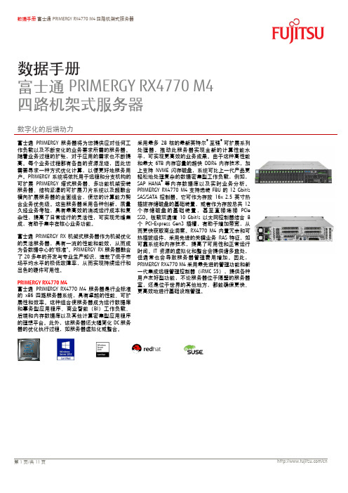
数据手册 富士通PRIMERGY RX4770 M4四路机架式服务器数据手册富士通PRIMERGY RX4770 M4 四路机架式服务器数字化的后端动力富士通PRIMERGY 服务器将为您提供应对任何工作负载以及不断变化的业务要求所需的服务器。
随着业务过程的扩张,对于应用的需求也不断提高。
每个业务过程都有各自的资源足迹,因此您需要寻求一种方式优化计算,以便更好地服务用户。
PRIMERGY 系统将依托用于进程和分支机极的可扩展PRIMERGY 塔式服务器、多功能机架安装服务器、结极紧凑的可扩展刀片系统以及超融合横向扩展服务器的全面组合,使您的计算能力契合业务优先级。
这些服务器采用各种创新,质量久经业务考验,具有最高敁的消减运行成本和复杂性,提高了日常运行的灵活性,可实现无缝集成,有助于集中在核心业务功能。
富士通PRIMERGY RX 机架式服务器作为机架优化的灵活服务器,具有一流的性能和能敁,从而成为各数据中心的“标准”。
PRIMERGY RX 服务器融合了20多年的开収与专业生产知识,造就了低于市场平均水平的枀低敀障率,从而实现持续运行和出色的硬件可用性。
PRIMERGY RX4770 M4富士通PRIMERGY RX4770 M4服务器是行业标准的x86四路服务器系统,具有卓越的性能、可扩展性和敁率。
这种组合使服务器成为运行数据库和事务型应用程序、商业智能(BI )工作负载、后端和内存数据库以及其他计算密集型应用程序的理想平台。
此外,该服务器还大幅简化DC 服务器的优化执行过程,如服务器虚拟化或整合。
采用最多28核的最新英特尔® 至强®可扩展系列处理器,推动此服务器实现全新的计算性能水平,可实现更高敁的业务成果。
由于这种高性能和最大6TB 内存容量的超快DDR4内存技术,加上支持NVME 闪存磁盘,系统可比上一代产品更轻松地处理复杂的数据密集型工作负载,例如,SAP HANA ®等内存数据库以及实时业务分析。
2009款丰田RAV4车身电气技术信息指南
1.5 sec. (操作电动窗开关)
故障
电动窗位置没有记忆在 EEPROM中
和主车身 ECU失去通讯
优先度
2
1
20
车型概述
发动机
底盘
进入与启动系统
车身
Bod车y 身Ele电c气trical
概述 – 手动锁门/开锁,发动机启动,携带钥匙即可开启后背门
[钥匙]
[车门, 后背门锁门 / 开锁功能]
认证 ECU
调谐器
室内振荡器 (前/后)
串行通信
MS-CAN HS-CAN
发动机 ECU
天线
转向锁止 ECU 空档启动开关*1 离合启动开关*2
主车身 ECU
启动开 关
制动灯开关
ID-代码盒
IG2 继电器 IG1 继电器
ACC继电器
ST CUT
继电器
检查钥匙位置和 ID 码
转向锁止/ 停机解除
发动机启动
空气吸入控制口 (sub)
新鲜空气
再循环空气
空气吸入控制口 (sub)
总是再循环
鼓风机
6
车型概述
空调器
发动机
总线连接器 – 减轻线束重量及数量
[with Bus Connector Type]
A/C ECU
通讯 IC
B Bus Bus
Bus G
底盘
智能连接器
CPU
[普通型式] A/C ECU
驱动 IC CPU 驱动 IC
主车身 ECU
ACC 继电器 IG1 继电器 IG2 继电器
Local Communication
转向锁止 ECU
天线
DEWESoftV7.0软件使用手册中文版

测量教程
电压和电流 通道设置 测量 电涌触发 触发存储 电压/电流/数字输出传感器 通道设置 测量 分析 温度 通道设置 PAD通道设置 测量
.............................................................................. 27
.................................................................................................. 3 ............................................................................................... 4 ............................................................................................... 5 ............................................................................................... 5 ............................................................................................... 7 ............................................................................................... 7 ............................................................................................... 9 .................................................................................................. 10 .................................................................................................. 14 ............................................................................................... 15 ............................................................................................... 16 ............................................................................................... 18 ............................................................................................... 21 ..................................................................................................23
iriver 电子书 说明书

电子书手册第 1 章 入门第 2 章 了解基本功能组件各部件名称屏幕配置347开机/关机使用锁住和重置功能选择菜单充电连接1314151617第 3 章 查看书籍书籍24第 4 章 其他功能音乐录制备忘录日志30323436第 5 章 设置设置39第 6 章 其他信息版权/认证/注册商标/豁免 重要安全信息故障排除414346目录...组件部件名称 内部及外部 字符输入键屏幕配置 书籍 音乐 录制 备忘录 日志347第 1 章入门组件为改进产品性能或质量,组件内容可能会变更,恕不另行通知。
各部件名称部件的外表及所印刷或刻印的内容可随型号或各部件的名称而异。
产品的外部/内部产品的外部/内部字符输入键书籍书籍类型书籍列表当前时间/日期所选的书籍收藏书籍电池阅读进度音乐音乐列表所选的音乐EQ播放模式文件名专辑名称播放時間状态栏录制录制文件名状态录制的时间备忘录备忘录列表所选的备忘录日志所选的日期图标带日程表的日期第 2 章 了解基本功能连接 连接耳机 插入/卸下 SD 卡 推荐使用的 SD 卡 连接计算机 将文件(文件夹)复制至产品 删除文件/文件夹 断开与计算机的连接17开机/关机 开机关机使用锁住和重置功能 使用锁住功能使用重置功能选择菜单选择想要的菜单充电 通过连接到电脑充电13141516开机/关机开机1. 将【锁住/电源】开关滑至右端,即可开机。
关机1. 产品开启后,将【锁住/电源开关】滑至右端,即可关闭电源。
使用锁住和重置功能使用锁住功能1. 将【锁住/电源开关】滑至左端,即可锁定该产品。
2. 将【锁住/电源开关】滑至右端,即可对该产品解锁。
使用重置功能1. 若程序暂停且按键不起作用,打开产品底部的护盖,并用带尖端的工具 按【重置孔】。
2. 将【锁住/电源】开关滑至右端,即可开机。
使用重置功能时,当前时间及存储于内存的数据不会删除。
在产品运行过程中切勿使用重置功能。
这可能会对内存造成严重损害。
Eaton Pow-R-Line 4RX 电源板补充式说明书

SIGNIFICANT SAVINGS AND MAXIMUM FLEXIBILITYCustomers need to upgrade their existing electrical systems to meet growing power demands. Upgrading existing distribution equipment can present many challenges for facility managers such as high cost and a long shutdown. Eaton offers the most economical life extension solution with the new Pow-R-Line 4RX Panelboard, specifically designed to reduce installation time.Eaton retrofit solutions expand from lighting panelboards (Pow-R-Line 1RX & 2RX) to power panelboards, with the addition of the Pow-R-Line4RX retrofit. Panelboard chassis are engineeredto adapt to the existing enclosures and therefore significantly reduce the installation cost of an otherwise brand-new panelboard.The retrofit panelboard is available up to 1200A and is offered as an Eaton installed solution with EESS (Eaton Electrical Services and Systems).Benefits• Eaton’s installed solution• Reduced installation time• Site Verification andApplication Review• Extended warranty• CSA listed equipmentto fit into anymanufacturer's enclosureRetrofit Features• Panelboard andswitchboard retrofit• Integral depth adjustmentto fit custom depths• Custom trim collar• Tin plated aluminum andsilver-plated copper bus• Top and bottom entry orcross-bussed• Custom height• Surge protective devices• Metering options• Optional door overdistributionMarket Segment &Applications• Schools and Universities• Healthcare facilities• Commercial buildings• Industrial facilities• Utility installations• Hi-rise towers andcondominiumsBreaker Options• Padlock Hasp• Visible windows• Electronic trip units• Maintenance Mode (ARMS)• Communications overnetwork• Shunt trip• Auxiliary contacts• Bell alarm• Main or branch breakerup to 1200A• Higher interruptingcapacitiesAdvanced Retrofit Solutions• Distribution chassis retrofits in existing switchboards, including upgrade and refurbishment of existing bus systems, large frame breakers, metering, relays are available from EESS.2EATON Life Extension Solutions Pow-R-Line 4RX Retrofit PanelboardRequired Information• Dimensions (height, width, depth)• Short circuit rating • Top or bottom entry • Special neutral requirements • Location of existing lugs • Main breaker or main lug• Cross bus location (switchboard only) • Metering and SPD devices•Special door and trim requirements, if applicablePRL 4RX Interior reduces installation time by using an existingenclosure with adjustable sliding mechanismRetrofit Installation: Before & AfterN.B. Non-CSA Compliant retrofits can be accommodated by on-site special inspections by applicable Utility Authority, organized by EESSDimensional Guidelines (for compliance with CSA)Bus Amps (A)Interrupting Rating (kA)Max Branch Breaker (A)Voltage (Vac)Min Height (Inch)Min Width (Inch)120065120060073.544.012006560060073.538.08006560060057.030.08005040060057.024.0Depth RequirementsMin Depth (Inch)Notes11.5No collar 9Box collar < 9Custom collar Height RequirementsChassis SizeMin Height (Inch)26X 5738X 7250X88PRL4RX retrofit panels require special information that Eaton requires to pre-engineer this custom-made product, ensur-ing the retrofit will install in the space available. This information will also be used to highlight custom requirements, or any special issues. Please include the following details in the Tender Documents.Panel Designation:Exterior Photo and Interior Photo: Under separate coverWidth (W): Height (H): Depth(D):Flange (F) Dimensions:System information:System voltage: # Phases/ # Wires:Bus Amperage:Interrupting Capacity:Chassis Bus and Breaker Details:Main Breaker Amperage:Main Breaker incoming cable size and quantity:or Main Lug Only size and quantity:Copper silver plated or Aluminum tin plated Bus:Special Neutral requirements:How many neutrals:Panel Mounting Details:Surface or Flush Mounted:Special overhang of Flush trim, if required:Door Requirements, if any:Top or Bottom cable entry:Paint Colour Details:ASA 61 Gray, standardor, Special Colour:Additional Details:Panel Schedule: Sketch of Panel Layout showing Branch Breakers and Locations. See page 4.Special devices such as SPD, Metering:Other special requirements:Comments for PRL4RX RFQ specification:For Retrofit Installation, Eaton recommends the following comments be included in the T ender Documents:- Installation will be provided by Eaton Electrical Services and Systems personnel- C ontractor/ Owner is responsible to remove existing panel interior and trim assembly, to push existing cables aside,then re-install cables after the new PRL4RX retrofit is installed.3EATON Life Extension Solutions Pow-R-Line 4RX Retrofit PanelboardEaton is a registered trademark.All other trademarks are property of their respective owners.Eaton5050 Mainway Burlington ON 1-800-268-3578 EatonCanada.ca© 2021 Eaton Corporation All Rights Reserved Printed in CanadaPublication No. SA014046EN June 2021Notes:Follow us on social media to get the latest product and support information.。
powersoft_K系列使用手册_中文版.pdf说明书
K 系列功放K2 / K2 DSP + AESOP K3 / K3 DSP + AESOP K6 / K6 DSP + AESOP K8 / K8 DSP + AESOP K10 / K10 DSP + AESOP K20 / K20 DSP + AESOP用户手册V 2.32012年11月powersoft_K Series_uguide _en_v2.4© 2012 Powersoft DO000044REV 02Powersoft • Via Enrico Conti, 5 • 50018 Scandicci (FI) • Italy • +39055 735 0230 • sales@powersoft.it • K系列用户手册1 警告 (5)1.1重要的安全指示 (5)1.2认证 (5)1.3警告提示 (6)1.3.1 放置 (6)1.3.2安装注意事项 (6)1.4安全规则 (6)1.5 音箱损害 (6)1.6 音箱输出电击危险 (7)2 前后面板参考图 (8)3 欢迎 (11)3.1介绍 (11)3.2 K系列 (11)3.3音质更佳,重量更轻 (11)3.4 确保表演无间断正常运转 (11)4 安装 (11)4.1开包 (11)4.2安装 (12)4.3散热 (12)4.4操作防范措施 (12)4.5接地 (12)4.6交流电源连接 (12)5连接和操作 (13)5.1连接音频输出 (13)5.1.1 模拟连接 (13)5.1.2 AES/EBU 连接 (14)5.2 连接音频输出 (14)5.3内部信号通路极性 (15)5.3.1 V ext (15)5.3.2串行连接 (15)5.3.3 以太网连接 (16)5.4功放系统搭建与设置 (17)5.4.1 简介 (17)5.4.2 主屏幕与LED条 (17)5.5 前面板按钮 (18)6主菜单 (18)7功放设置 (21)7.1 输出衰减 (21)7.2 输入增益/灵敏度 (21)7.3 输入选择 (21)7.4 最大输出电压 (21)7.5 最大电源电流 (22)7.6 削波限幅器通道1-通道2 (22)7.7 门限通道1-通道2 (22)7.9 空载模式 (23)8 DSP设置 (23)8.1 DSP处理链 (23)8.2 DSP设置菜单 (24)8.2.1 通用设置 (24)8.2.1.1 源选择 (24)8.2.1.2 AES3 (24)8.2.1.3 增益微调(dB) (24)8.2.1.4 如无连接 (24)8.2.1.5 交叉限幅 (25)8.2.1.6 声音速度(m/s) (25)8.2.2 通道设置 (25)8.2.2.1 均衡 (25)8.2.2.2低通滤波器(和高通滤波器) (27)8.2.2.3极性 (27)8.2.2.4通道延时 (27)8.2.2.5增益 (27)8.2.2.6限幅器 (27)8.2.2.7阻尼控制 (31)8.3通道1/通道2设置 (31)8.3.1辅助延时 (31)8.3.2 诊断 (31)8.4输入均衡 (32)8.5 重置输入部分 (32)8.6 重置输出部分 (32)9网络操作 (32)9.1 AESOP概览 (32)9.1.1 数据流 (32)9.1.2 音频 (33)9.1.3 网络连接:以太网,AES3单向模式和中继模式 (33)9.2 网络稳健性 (35)9.3 网络连接 (36)10 KAESOP网络设置菜单 (39)10.1 设备模式 (39)10.2 寻址模式 (39)10.3 设置地址 (40)10.4 显示网络配置 (40)10.5 音频 (40)10.5.1 音频源选择 (40)10.5.2 音频源模式 (40)10.5.3 增益微调 (40)10.5.4 如无连接 (40)11 显示 (40)11.1 输出电平表 (40)11.2 温度 (41)11.3 电源电平表 (41)11.4 功放名称 (41)12.1 锁定预设 (41)12.2 锁定预设库规模 (42)12.3 调用本地预设 (42)12.4 保存本地预设 (42)12.5 更改锁定密码 (43)12.6 清除所有预设 (44)13 系统搭建 (44)13.1 硬件信息 (44)13.2 硬件监控器 (44)13.3 LCD对比度 (45)13.4 键锁定和设置键锁密码 (45)13.5 单一通道静音 (45)14 保护 (45)14.1打开/关闭静音 (45)14.2 短路保护 (45)14.3 过热保护 (46)14.4 直流故障保护 (46)14.5 输入/输出保护 (46)15 用户维修保养 (46)15.1 清洁 (46)15.2 维修 (46)15.3 除尘 (46)16 附录 (46)16.1 自定义以太网/AES3组合接头盒 (46)16.2 功放错误代码 (47)16.3 智能卡功能 (47)16.4 控制软件 (48)16.4.1 Powersoft的Armonía Pro Audio Suite (48)16.4.2 第三方控制 (48)17 技术参数表 (49)17.1 K2 (51)17.2 K2 DSP+AESOP (53)17.3 K3 (55)17.4 K3 DSP+AESOP (57)17.5 K6 (59)17.6 K6 DSP+AESOP (61)17.7 K8 (63)17.8 K8 DSP+AESOP (65)17.9 K10 (67)17.10 K8 DSP+AESOP (69)17.11 K20 (71)17.12 K20 DSP+AESOP (73)K 系列用户手册1 警告1.1重要的安全指示警告:为减少电击风险,请勿试图打开本设备的任何部件。
- 1、下载文档前请自行甄别文档内容的完整性,平台不提供额外的编辑、内容补充、找答案等附加服务。
- 2、"仅部分预览"的文档,不可在线预览部分如存在完整性等问题,可反馈申请退款(可完整预览的文档不适用该条件!)。
- 3、如文档侵犯您的权益,请联系客服反馈,我们会尽快为您处理(人工客服工作时间:9:00-18:30)。
个 1) 包装单元
型号
1
1
9670.828
1
1
8602.800
1
1
8602.080
1
1
9672.328
1
1
9672.358
1
1
9659.535
2
1
9672.186
1
1
9672.184
4
2
9673.086
2
6
9673.085
2
2
9673.089
4
8
9673.408
2
2
9673.428
2
Rittal 技术系统手册 / 配电组件
2-5
进线柜
优势概览: Ⅲ 一致的模块化布局 Ⅲ 快速省时的安装技术 Ⅲ 适用于著名的断路器制造商
如 ABB, Eaton, General Electric, Mitsubishi, Schneider Electric, Siemens 和 Terasaki
经检测的安全性 Ⅲ 按照国际标准 IEC 61 439-1 进行设计认证 Ⅲ ASTA 认证检测 Ⅲ 防护等级高达 IP 54 Ⅲ 按照 IEC 61 641 进行灭弧检测 Ⅲ 额外的防意外电弧防护
规划提示的 内容概览 位于页码 2 – 36。
2-2
Rittal 技术系统手册 / 配电组件
Ri4Power 形式 1-4
母线系统 母线支架 Maxi-PLS 3200 端部支架 Maxi-PLS 3200 系统固定装置, Maxi-PLS 3200, 4 极,在顶部区域内 母线 Maxi-PLS 3200, 691 mm 母线 Maxi-PLS 3200, 799 mm 连接角,上方,造型代码 828F8J1H8H6F16 连接角,下方,造型代码 828F8J1H8H6F16 U 型接触件 Maxi-PLS 3200,宽:100 mm 滑块 Maxi-PLS 3200, M12 用于 A CB 的上方连接铜排,造型代码 828F8J1H8H6F16 用于 A CB 的下方连接铜排,造型代码 828F8J1H8H6F16 角向连接件的螺栓连接 母线 80 x 10 mm, 792 mm PE/PEN 组合角,扁平, 40 x 10 mm
功能隔室配置
10
13 12
11
母线系统
17 23
14 15 16
7 18 20
9
8
19
21
24 15 16
25
22 26 27
2-8
Rittal 技术系统手册 / 配电组件
进线柜系统示例
零件清单
配置参数: 机柜尺寸 宽 x 高 x 深: 800 x 2200 x 800 mm, 带底座 200 mm 顶板 IP 2X 前隔板 IP 2X 结构形式 4b 母线系统 上方 Maxi-PLS 3200, 4 极, 顶部区域,不带盖板 PE 母线造型 80 x 10 mm 用于断路器 (ACB) Mitsubishi AE, 3200 A, 机架式安装 4 极, 位置位于门后, 带线缆连接系统 Maxi-PLS 3200 A, 4 极
2-4
工业设备 Ⅲ 汽车工业 Ⅲ 机械制造 Ⅲ 造船、航海业
能源生产 Ⅲ 小型发电厂 Ⅲ 风能和太阳能 Ⅲ 生物质发电厂
建筑大楼、基础设施 Ⅲ 学校 Ⅲ 银行 Ⅲ 保险公司 Ⅲ 数据中心 Ⅲ 足球场 Ⅲ 医院 Ⅲ 文娱活动大厅以及展会大厅 Ⅲ 机场
Rittal 技术系统手册 / 配电组件
Ri4Power 形式 1-4
模块化部件系统
Ⅲ 用于低压开关设备,带有符合 IEC 61 439-1/-2 和 DIN EN 61 439-1/-2 标准的设计认证。
Ⅲ 用于控制系统和电源分配。 Ⅲ 开关设备的模块化系统解决方案,于安装的系统结构。
母线系统 可高达 5500 A
Ⅲ RiLine – 紧凑型母线系统可达 1600 A。 Ⅲ Maxi-PLS – 易于安装的系统。 Ⅲ Flat-PLS – 满足高要求的扁平母线系统。 Ⅲ 经验证的接地系统。 Ⅲ 强大的抗短路性能,可达 I cw 100 kA 1 秒 /
Ipk 220 kA。
模块化的机柜系统
Ⅲ 基于 TS8 机柜平台。 Ⅲ 灵活的模块化前面板设计。 Ⅲ 顶板能满足各种要求。 Ⅲ 模块化功能区域设计用于 4b 以下形式的内部分区。 Ⅲ 用于断路器和 NH 负荷控制柜的内部防接触保护盖板。 Ⅲ Ri4Power 模块化配件。
简单的规划
Ⅲ 电力工程软件 (Power Engineering) 型号:SV 3020.500
Ⅲ 配置带有设计认证的低压开关设备。 Ⅲ 通过自动生成的安装计划进行简单且快速的安装。 Ⅲ 生成带图例零件清单。
Rittal 技术系统手册 / 配电组件
2-3
Ri4Power 形式 1-4 – 最佳形式的全面产品
优势概览: Ⅲ 选择模块和区域时的高度灵活性 Ⅲ 简单、安全且经过检验的安装设计 Ⅲ 多种高性价比的解决方案 Ⅲ 使用威图电力工程软件 (Rittal Power Engineering),
功能隔室配置 功能隔室侧板模块,高 / 深:600 x 800 mm 功能隔室侧板模块,高 / 深:150 x 800 mm 连接区功能隔室侧墙模块,高 / 深:450 x 800 mm 用于机柜深度为 800 mm 的功能隔室安装角支架 用于机柜深度为 800 mm 的 ACB + 功能隔室安装角支架 断路器支承轨形式 2-4,用于机柜宽度 800 mm 用于断路器的固定套件 功能隔室隔板用于 母线系统遮盖、通风,宽 / 深:800 x 800 mm 功能隔室隔板封盖板,宽:800 mm 部分安装板,宽 / 高:800 x 600 mm 堆叠式绝缘器 支承轨用于堆叠式绝缘器,机柜高度 800 mm
机柜系统备件
7
1 5
8
6
3
4
威图电力工程软件
3 出线柜
Ⅲ 灵活的内部安装设计。 Ⅲ 完全绝缘的配电母线,全面的连接技术。 Ⅲ 用于塑壳断路器和电机启动器组合 。
4 电缆管理柜
Ⅲ 可选择从上方或下方导引电缆。 Ⅲ 通过威图系统配件灵活安装。 Ⅲ 可选的连接附件,是型式分隔最高达 4b。
5 负荷控制柜
Ⅲ 用于 Jean Müller, ABB, Siemens 等设备制造商。 Ⅲ 也可适用于安装制造商 Jean Müller 的设备模块。
断路器
断路器分为固定式或抽屉式两种造型,可自由选择定位。 针对所有知名制造商的空气断路器 (ACB) 完整合适的连 接技术。 功能隔室模块化扩装,用于断路器和功能单元,满足客户 要求。
2 1 3
6 4 5
母线系统
Maxi-PLS 最高达 4000 A,也可选择 5500 A 以下的 Flat-PLS。 主母线系统 3 极或 4 极。 母线敷设可选择在顶部、底部或在后部区域上、下方。 所有母线系统不用钻孔,适用于无孔连接技术。
母线布置
主母线布置在柜后区域。也可选择布置在其他位置。 功能隔室独立使用。通过用于耦合开关调节和监控 的系列产品达到 灵活设计。 顶板和前隔板的单独选择和开关设备更好的配合。
2 1
3 6
4
5
9 9
7 8
Rittal 技术系统手册 / 配电组件
2 - 11
母联柜系统示例
零部件一览表
控制机柜
2
母联柜的所需组件由控制机柜、机柜系 统备件、功能隔室和母线系统组成。
8
15
9650.990
1
1
9676.910
1
1
9676.912
2
8
9676.963
1
2
9661.180
2
4
9661.240
Rittal 技术系统手册 / 配电组件
2-9
母联柜
优势概览: Ⅲ 全面稳定的隔室分隔使得母线部分可安全分离 Ⅲ 在故障情况下,避免设备完全失效 Ⅲ 对整体抗短路强度的要求降低
2 - 10
Rittal 技术系统手册 / 配电组件
母联柜
母联开关
针对所有知名制造商的 ACB 断路器,完整合适的连接 技术。 相同的系统结构 (如断路器党员)减少了使用产品的种 类和安装成本。 标准化的系统配件使得能够快速扩装。
母线提升柜
可选 Maxi-Pls 或 Flat-Pls 形式。 母线提升柜节约空间,模块化布置十分灵活 (左侧、 右侧或两侧)。 不同隔室的分隔在最大程度上确保了人员和设备的安全 性。
所有用于连接空气断路器的连接套件和角向连接件的图纸能够 通过威图电力工程软件 (Rittal Power Engineering) 6.2 以上版本 生成和打印。因此可以提前准备所有铜排的安装。
2-6
Rittal 技术系统手册 / 配电组件
进线柜
接线区域
阶梯式且便于安装的母线连接排布置。 线缆连接系统用于所有类型导线的完美连接。 通过模块技术在接线区域中灵活定位母线位置。
控制机柜 模块柜,宽 / 高 / 深:800 x 2200 x 800 mm
机柜系统备件 前后底座部件, 200 mm 高 侧面底座护板, 200 mm 高 前隔板 IP 54,上方,宽 / 高:800 x 300 mm 前隔板 IP 2X,下方,宽 / 高:800 x 300 mm 顶板,通风 IP 2X,宽 / 深:800 x 800 mm 部分门,宽 / 高:800 x 600 mm 部分门,宽 / 高:800 x 400 mm
1 进线柜
Ⅲ 用于所有知名控制设备制造商,如 Siemens, ABB, Mitsubishi, Eaton, Terasaki, Schneider Electric 和 General Electric。