系列数字存储示波器使用说明书
数字存储示波器使用说明
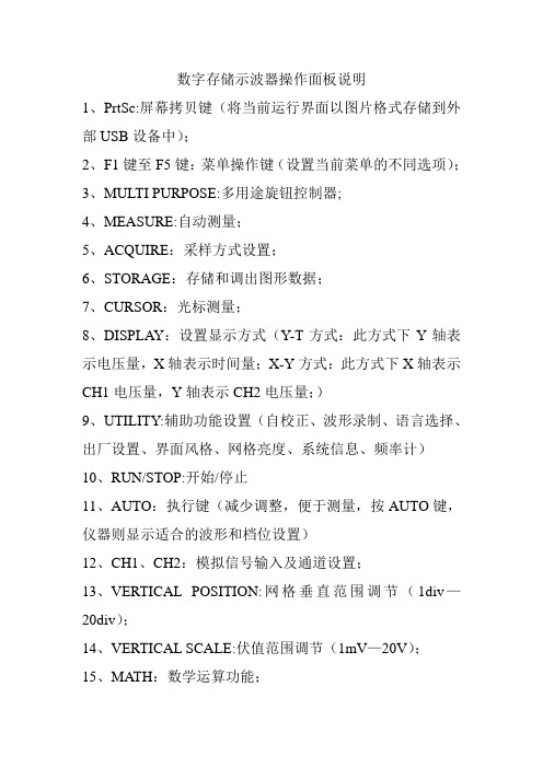
数字存储示波器操作面板说明1、PrtSc:屏幕拷贝键(将当前运行界面以图片格式存储到外部USB设备中);2、F1键至F5键:菜单操作键(设置当前菜单的不同选项);3、MULTI PURPOSE:多用途旋钮控制器;4、MEASURE:自动测量;5、ACQUIRE:采样方式设置;6、STORAGE:存储和调出图形数据;7、CURSOR:光标测量;8、DISPLAY:设置显示方式(Y-T方式:此方式下Y轴表示电压量,X轴表示时间量;X-Y方式:此方式下X轴表示CH1电压量,Y轴表示CH2电压量;)9、UTILITY:辅助功能设置(自校正、波形录制、语言选择、出厂设置、界面风格、网格亮度、系统信息、频率计)10、RUN/STOP:开始/停止11、AUTO:执行键(减少调整,便于测量,按AUTO键,仪器则显示适合的波形和档位设置)12、CH1、CH2:模拟信号输入及通道设置;13、VERTICAL POSITION:网格垂直范围调节(1div—20div);14、VERTICAL SCALE:伏值范围调节(1mV—20V);15、MATH:数学运算功能;16、HORI MENU:设置触发释抑时间(重新启动触发电路的时间间隔,旋动多用途旋钮控制器设置),开启视窗扩展(提高波形的水平扩展倍数);17、HORIZONTAL POSITION:调整波形窗口的水平位置;18、HORIZONTAL SCALE:改变水平时基档位设置(扫描速率:2ns—50s,以1—2—5方式步进);19、SET TO ZERO:将垂直位移、水平位移、触发释抑的位置回到中点,以及把触发电平设置到50%;20、TRIG MENU:触发菜单按键;21、FORCE:强制触发按键;22、HELP:帮助;23、EXT TRIG:外触发输入;24、PROBE COMP:探头补偿信号输出;作用:示波器是一种测量电压波形的仪器,甚至可以说它是一种能够看到图象的电压表。
数字存储示波器操作手册
步骤1.轻轻地拔出把手的底部。
2.旋转把手至其中一个预设位置。
3.连接电源线。
4.按下电源开关。显示器约在10秒内启动。
5.通过调取工厂设置重设系统。按Save/Recall键,然后按Default Setup键。
DC-100MHz(-3dB)
2
GDS-1152A
DC-150MHz(-3dB)
2
性能
·1GS/s实时采样率
·25GS/s等效采样率
·2M点记录长度
·高达10ns峰值检测
·2mV~10V垂直刻度
·1ns~50s时间刻度
特性
·5.6英寸彩色TFT显示器
·储存并调取设置和波形
·27组参数自动测量
·多语言菜单(12种语言)
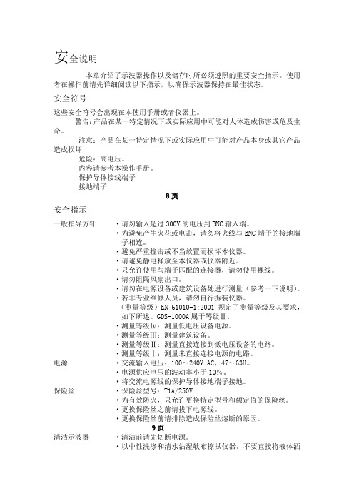
将带有裸线的电缆,插头或其它连接器与火线插座相连非常危险。若已确认电缆或插座存在危险,必须关闭电源,拔下电缆、保险丝和保险丝座。并且根据以上标准立即更换电线和保险丝。
11页
产品介绍
本章介绍了示波器的主要特性,外观及操作步骤。
主要特性
机型
频宽
输入通道
GDS-1062A
DC-60MHz(-3dB)
2
GDS-1102A
·温度:-10℃至60℃
英制电源线
在英国使用此示波器时,请确保电源线符合以下安全说明。
注意:导线/装置的连接必须有专业人员操作。
警告:此装置必须接地。
重要:导线的颜色均根据以下说明标识:
绿色/黄色: 地线
蓝色: 零线
棕色: 火线(相线)
GDS-2102型数字存储示波器使用说明
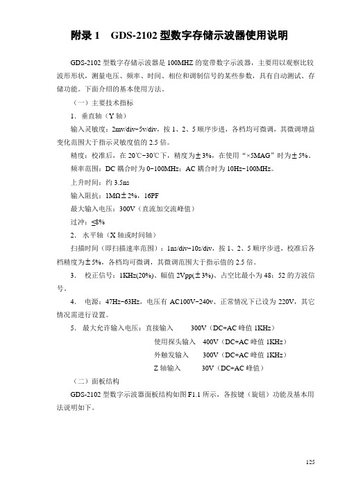
附录1 GDS-2102型数字存储示波器使用说明GDS-2102型数字存储示波器是100MHZ的宽带数字示波器,主要用以观察比较波形形状,测量电压、频率、时间、相位和调制信号的某些参数,具有自动测试、存储功能。
下面介绍的基本使用方法。
(一)主要技术指标1.垂直轴(Y轴)输入灵敏度:2mv/div~5v/div,按1、2、5顺序步进,各档均可微调,其微调增益变化范围大于指示灵敏度值的2.5倍。
精度:校准后,在20℃~30℃下,精度为±3%,在使用“×5MAG”时为±5%。
频率范围:DC耦合时为0~100MHz;AC耦合时为10Hz~100MHz。
上升时间:约3.5ns输入阻抗:1MΩ±2%,16PF最大输入电压:300V(直流加交流峰值)过冲:≤8%2.水平轴(X轴或时间轴)扫描时间(即扫描速率范围):1ns/div~10s/div,按1、2、5顺序步进,校准后各档精度为±5%,各档均可微调,其微调范围大于指示值的2.5倍。
3.校正信号:1KHz(20%)、幅值2Vpp(±3%)、占空比最小为48:52的方波信号。
4.电源:47Hz~63Hz,电压有AC100V~240v、正常情况下已设为220V,其它情况需进行设置。
5.最大允许输入电压:直接输入300V(DC+AC峰值1KHz)使用探头输入400V(DC+AC峰值1KHz)外触发输入300V(DC+AC峰值1KHz)Z轴输入30V(DC+AC峰值)(二)面板结构GDS-2102型数字示波器面板结构如图F1.1所示,各按键(旋钮)功能及基本用法说明如下。
125126A LCDB F1~F5 Variable D ON/ E Main Trigger Trigger Horizontal Horizontal Time/K Vertical L CH1~CH2 M Volts/TriggerInputTerminal key Connector ON/OFF keyCompensation Output Terminal CH1~CH2图F1.1 GDS-2102型数字示波器前面板结构前面板说明ALCD 显示器 TFT 彩色LCD 显示器具有320×234 的分辨率。
示波器说明书

DS-1000/2000 系列数字存储示波器使用说明书二、面板和操作说明DS-2000系列示波器前面板如图1-1所示,面板操作说明如图1-2所示,面板包括旋钮和功能按键。
旋钮控制类似模拟示波器,如移位(POSITION)、电平(LEVEL)、档级(VOLTS/DIV)。
功能按键主要是选择各种不同功能的菜单和运行的控制。
1、菜单操作键,在液晶屏幕右侧显示相应的菜单,用未标记的五个菜单操作键来进行选项,示波器使用下列二种方法显示菜单选项,如图1-3所示。
a、循环列表,每次按下选项按钮时,示波器都会将参数设定为不同的值。
b、动作,按下运作选项按钮时立即发生的动作类型。
图1-4 显示界面三、功能检查1、接通仪器电源并打开,片刻后按任意键进入测试界面,如图1-4所示。
2、将示波器探头连接至通道(CH1)并将探极上的衰减开关设定为×10,并将探头连接器上的插槽对准CH1的输入插座(BNC)的凸键上,插入并右转以锁定到位,如图1-5所示。
3、将探头端部和接地夹连接至探头补偿器的输出端,按见示波显示(3V,1KHz)。
如图1-6所示。
4、以同样的方法检查通道2(CH2)CH1,按CH2菜单键打开通道2,重复步骤2和步骤3。
四、探头补偿1、按上述功能检查,连接示波器和探头,并按AUTO/SET 键,显示波形。
2、检查所显示波形形状。
如图1-7所示。
3、如有必要,调探头上的可变电容,至屏幕上显示的波形补偿正确。
五、自动设置本仪器具有自动设置功能,根据输入信号可自动调整,垂直、时基、触发方式来显示合适的波形,应用自动设置时要求被测信号的频率大于或等于50Hz,占空比大于1%。
1、将被测信号连接至通道输入端。
2、按下AUTO/SET键,波形将会自动显示,如需要,可手工调整,以达到你所需最佳波形。
六、垂直系统如图1-8所示,为垂直控制区图1—81、POSITION转动该旋钮可使波形上下移动。
2、VOLTS/DIV转动该旋钮可改变垂直放大器的放大档级,有粗调细调两档。
NDS 双通道系列数字存储示波器 用户手册说明书
NDS双通道系列数字存储示波器用户手册官方微信,一扫即得如需资料下载,请登录:/download2023.03版本V1.6.3©福建利利普光电科技有限公司版权所有,保留所有权利。
产品受专利权的保护,包括已取得的和正在申请的专利。
本文中的信息将取代所有以前出版资料中的信息。
本手册信息在印刷时是正确的。
然而,福建利利普光电科技有限公司将继续改进产品并且保留在任何时候不经通知的情况下变动规格的权利。
是福建利利普光电科技有限公司的注册商标。
福建利利普光电科技有限公司福建漳州市蓝田工业开发区鹤鸣路(原横三路)19号利利普光电科技楼Tel: 4006-909-365 Fax:************Web: E-mail:*************.cn保修概要本公司保证,本产品从本公司公司最初购买之日起3年(配件1年)期间,不会出现材料和工艺缺陷。
配件如探头、电池等保修期1年。
本有限保修仅适于原购买者且不得转让第三方。
如果产品在保修期内确有缺陷,则本公司将按照完整的保修声明所述,提供维修或更换服务。
如果在适用的保修期内证明产品有缺陷,本公司可自行决定是修复有缺陷的产品且不收部件和人工费用,还是用同等产品(由本公司决定)更换有缺陷的产品。
本公司作保修用途的部件、模块和更换产品可能是全新的,或者经维修具有相当于新产品的性能。
所有更换的部件、模块和产品将成为本公司的财产。
为获得本保证承诺的服务,客户必须在适用的保修期内向本公司通报缺陷,并为服务的履行做适当安排。
客户应负责将有缺陷的产品装箱并运送到本公司指定的维修中心,同时提供原购买者的购买证明副本。
本保证不适用于由于意外、机器部件的正常磨损、在产品规定的范围之外使用、使用不当或者维护保养不当或不足而造成的任何缺陷、故障或损坏。
本公司根据本保证的规定无义务提供以下服务:a) 维修由非本公司服务代表人员对产品进行安装、维修或维护所导致的损坏;b) 维修由于使用不当或与不兼容的设备连接造成的损坏;c) 维修由于使用非本公司提供的电源而造成的任何损坏或故障;d) 维修已改动或者与其他产品集成的产品(如果这种改动或集成会增加产品维修的时间或难度)。
优利德 UTD2000CEX+系列使用手册 说明书

UTD2000系列数字存储示波器用户手册序 言尊敬的用户:您好!感谢您选购优利德仪器,为了正确使用本产品,请在使用之前仔细阅读说明书,特别留意“安全注意事项”的部分。
如果您已经阅读完本说明书全文,建议您将说明书妥善的保管,以便在使用过程中进行查阅。
版权与声明版权信息优利德科技(中国)股份有限公司版权所有。
商标信息UNI-T是优利德科技(中国)股份有限公司[UNI-TREND TECHNOLOGY(CHINA)CO., LTD]的注册商标。
文档版本UTD2000-20210618-REV.1声明●UNI-T 产品受中国或其他国家专利权的保护,包括已取得或正在申请的专利。
●本公司保留更改产品规格和价格的权利●UNI-T 保留所有权利。
许可软件产品由UNI-T 及其子公司或提供商所有,受国家版权法及国际条约规定的保护。
本文中的信息将取代所有以前出版的资料中的信息。
如果原购买者自购买该产品之日起三年内,将该产品出售或转让给第三方,则保修期应为自原购买者从UNI-T或授权的UNI-T分销商购买该产品之日起三年内。
探头及其他附件和保险丝等不受此保证的保护。
如果在适用的保修期内证明产品有缺陷,UNI-T可自行决定是修复有缺陷的产品且不收部件和人工费用,或用同等产品(由UNI-T决定)更换有缺陷的产品。
UNI-T作保修用途的部件、模块和更换产品可能是全新的,或者经修理具有相当于新产品的性能。
所有更换的部件、模块和产品将成为UNI-T的财产。
以下提到的“客户”是指据声明本保证所规定权利的个人或实体。
为获得本保证承诺的服务,“客户”必须在适用的保修期内向UNI-T通报缺陷,并为服务的履行做适当安排。
客户应负责将有缺陷的产品装箱并运送到UNI-T指定的维修中心,同时预付运费并提供原购买者的购买证明副本。
如果产品要运送到UNI-T维修中心所在国范围内的地点,UNI-T应支付向客户送返产品的费用。
如果产品送返到任何其他地点,客户应负责支付所有的运费、关税、税金及任何其他费用。
TDS1000B和TDS2000B系列数字存储示波器的说明书
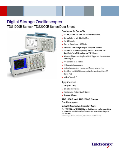
Digital Storage OscilloscopesTDS1000B Series•TDS2000B Series Data SheetFeatures&Benefits40MHz,60MHz,100MHz,and200MHz BandwidthsSample Rates up to2GS/s Real Time2or4ChannelsColor or Monochrome LCD DisplayRemovable Data Storage using the Front-panel USB PortSeamless PC Connectivity through the USB Device Port,withOpenChoice®and NI SignalExpress®PC SoftwareAdvanced Triggers including Pulse Width Trigger and Line-selectableVideo TriggerFFT Standard on All Models12Automatic MeasurementsMultiple-language User Interface and Context-sensitive HelpDirect Print to all PictBridge®-compatible Printers through the USBDevice PortLifetime Warranty*1ApplicationsDesign and DebugEducation and TrainingManufacturing Test and Quality ControlService and RepairTDS1000B and TDS2000B SeriesOscilloscopesInstantly Productive.Incredibly Easy.The TDS1000B and TDS2000B Series digital storage oscilloscopes deliveran unbeatable combination of performance and ease of use,at a priceyou can afford.*1Limitations apply.For terms and conditions,visit /lifetimewarranty.DataSheetQuickly and easily capture waveforms.Affordable Digital PrecisionWith up to200MHz bandwidth and2GS/s maximum sample rate,no other color digital storage oscilloscope offers as much bandwidth and sample rate for the price.The TDS1000B and TDS2000B Series oscilloscopes provide accurate real-time acquisition up to their full bandwidth,the same record length at all time base settings,advanced triggers to isolate signals of interest,and12standard automatic measurements on all models.Their Fast Fourier Transform(FFT)and waveform add,subtract,and multiply math functions allow you to analyze,characterize,and troubleshoot circuits. Quick and Easy Waveform CaptureThe simple user interface with classic analog-style controls makes these instruments easy to use,reducing learning time and increasing efficiency. Innovative features such as the Autoset Menu,Probe Check Wizard, Context-sensitive Help Menu,and color LCD display(TDS2000B Series) optimize instrument setup and operation.Flexible Data TransferWith USB host and device ports which enable removable data storage, seamless PC connectivity,and direct printing,no other color or monochrome digital storage oscilloscope offers as muchflexibility and ease of data transfer for the price.Simple Documentation and AnalysisEasily capture,save,and analyze measurement results with OpenChoice PC Communications Software.Simply pull screen images and waveform data into the stand-alone desktop application or directly into Microsoft Word and Excel.To complement OpenChoice,National Instruments SignalExpress Tektronix Edition Software provides you with extended capabilities,including advanced analysis,remote oscilloscope control,and live waveform analysis.Alternatively,if you prefer not to use the PC,you Conveniently use your USBflash drive to store screenshots and waveformdata. Easily capture,save,and analyze measurement results with OpenChoice PCCommunications Software.can simply print your image directly to any PictBridge-compatible printer using the USB device port.Performance You Can Count OnDepend on Tektronix to provide you with performance you can count on. In addition to industry-leading service and support,every TDS1000B and TDS2000B Series oscilloscope comes backed with a Lifetime Warranty*1 as standard.*1Limitations apply.For terms and conditions,visit /lifetimewarranty.Digital Storage Oscilloscopes—TDS1000B Series•TDS2000B SeriesCharacteristicsTDS1000B and TDS2000B Series Digital Storage OscilloscopesTDS1001B TDS1002B TDS1012B TDS2002B TDS2004B TDS2012B TDS2014B TDS2022B TDS2024B Display(1/4VGA LCD)Mono Mono Mono Color Color Color Color Color Color Bandwidth*240MHz60MHz100MHz60MHz60MHz100MHz100MHz200MHz200MHz Channels222242424 External TriggerInputIncluded on all modelsSample Rate onEach Channel500MS/s 1.0GS/s 1.0GS/s 1.0GS/s 1.0GS/s 1.0GS/s 1.0GS/s 2.0GS/s 2.0GS/s Record Length 2.5K points at all time bases on all modelsVerticalResolution8bitsVerticalSensitivity2mV to5V/div on all models with calibratedfine adjustmentDC VerticalAccuracy±3%on all modelsVertical Zoom Vertically expand or compress a live or stopped waveformMaximum InputVoltage300V RMS CAT II;derated at20dB/decade above100kHz to13V p-p AC at3MHzPosition Range2mV to200mV/div+2V;>200mV to5V/div+50VBandwidth Limit20MHz for all modelsInput Coupling AC,DC,GND on all modelsInputImpedance1MΩin parallel with20pFTime Base Range 5ns to50s/div5ns to50s/div5ns to50s/div5ns to50s/div5ns to50s/div5ns to50s/div5ns to50s/div 2.5ns to50s/div2.5ns to50s/divTime BaseAccuracy50ppmHorizontalZoomHorizontally expand or compress a live or stopped waveformI/O InterfacesUSB Ports USB host port on front panel supports USBflash drivesUSB device port on back of instrument supports connection to PC and all PictBridge-compatible printersGPIB OptionalNonvolatile StorageReferenceWaveformDisplay(2)2.5K point reference waveformsWaveformStorage w/oUSB FlashDrive(2)2.5K point(2)2.5K point(2)2.5K point(2)2.5K point(4)2.5K point(2)2.5K point(4)2.5K point(2)2.5K point(4)2.5K pointMaximum USBFlash DriveSize64GBWaveformStorage withUSB FlashDrive96or more reference waveforms per8MBSetups w/oUSB FlashDrive10front-panel setupsSetups withUSB FlashDrive4000or more front-panel setups per8MBScreen Imageswith USB FlashDrive128or more screen images per8MB(the number of images depends onfile format selected)Save All with USB Flash Drive12or more Save All operations per8MBA single Save All operation creates3to9files(setup,image,plus onefile for each displayed waveform)*2Bandwidth is20MHz at2mV/div,all models.3Data SheetAcquisition ModesPeak Detect–High-frequency and random-glitch capture.Captures glitches as narrow as12ns(typical)at all time base settings from5μs/div to50s/div. Sample–Sample data only.Average–Waveform averaged,selectable:4,16,64,128.Single Sequence–Use the Single Sequence button to capture a single triggered acquisition sequence.Roll Mode–At acquisition time base settings of>100ms/div.Trigger SystemTrigger Modes–Auto,Normal,Single Sequence.Trigger TypesEdge(rising/falling)–Conventional level-driven trigger.Positive or negative slope on any channel.Coupling selections:AC,DC,Noise Reject,HF Reject,LF Reject. Video–Trigger on all lines or individual lines,odd/even or allfields from composite video,or broadcast standards(NTSC,PAL,SECAM).Pulse Width(or Glitch)–Trigger on a pulse width less than,greater than,equal to,or not equal to,a selectable time limit ranging from33ns to10s.Trigger Source2-channel Models–CH1,CH2,Ext,Ext/5,AC Line.4-channel Models–CH1,CH2,CH3,CH4,Ext,Ext/5,AC Line.Trigger ViewDisplays trigger signal while trigger view button is depressed.Trigger Signal Frequency ReadoutProvides a frequency readout of the trigger source.CursorsTypes–Amplitude,Time.Measurements–ΔT,1/ΔT,ΔV.Automatic Waveform MeasurementsPeriod,Frequency,+Width,–Width,Rise Time,Fall Time,Max,Min,Peak-to-Peak, Mean,RMS,Cycle RMS.Waveform MathOperators–Add,Subtract,Multiply,FFT.FFT–Windows:Hanning,Flat Top,Rectangular;2048sample points.Sources–2-channel models:CH1–CH2,CH2–CH1,CH1+CH2,CH1×CH2.4-channel models:CH1–CH2,CH2–CH1,CH3–CH4,CH4–CH3,CH1+CH2, CH3+CH4,CH1×CH2,CH3×CH4.Autoset MenuSingle-button,automatic setup of all channels for vertical,horizontal,and trigger systems,with undo Autoset.Signal Type Autoset Menu ChoicesSquare Wave Single Cycle,Multicycle,Rising orFalling EdgeSine Wave Single Cycle,Multicycle,FFT Spectrum Video(NTSC,PAL,SECAM)Field:All,Odd,or EvenLine:All or Selectable Line Number AutorangeAutomatically adjust vertical and/or horizontal oscilloscope settings when probe is moved from point to point,or when the signal exhibits large changes.Display CharacteristicsDisplay–Color models:¼VGA passive color LCD with color on black background with adjustable multilevel contrast.Monochrome models:¼VGA backlit passive LDC with adjustable multilevel contrast and inverse video selectable from front panel.Interpolation–Sin(x)/x.Display Types–Dots,vectors.Persistence–Off,1s,2s,5s,infinite.Format–YT and XY.Multiple-language User Interface and Context-sensitive HelpLanguages Available–English,French,German,Italian,Japanese,Korean, Portuguese,Russian*3,Simplified Chinese,Spanish,Traditional Chinese. Environmental and SafetyTemperature–Operating:0to+50ºC.Nonoperating:–40to+71ºC.Humidity–Operating and Nonoperating:Up to80%RH at or below+40ºC.Operating and Nonoperating:Up to45%RH up to+50ºC.Altitude–Operating and Nonoperating:Up to3,000m.Electromagnetic Compatibility–Meets Directive89/336/EEC,amended by93/68/EEC,meets or exceed EN55011Class A Radiated and Conducted Emissions;FCC47CFR,Part15,Subpart B,Class A;Australian EMC Framework, demonstrated per Emission Standard AS/NZS2064;Russian GOST EMC regulations.Safety–UL61010-1:2003,CSA22.2No.61010-1:2003,EN61010-1:2001,IEC61010-1:2001.Physical CharacteristicsInstrumentDimensions mm in.Width326.312.85Height158.0 6.22Depth124.2 4.89Weight kg lb. Instrument Only 2.0 4.4With accessories 2.2 4.9 Instrument ShippingPackage Dimensions mm in.Width476.218.75Height266.710.5Depth228.69.0RM2000B Rackmount mm in.Width482.619.0Height177.87.0Depth108.0 4.25*3Requires Russianfirmware,indicated by"RUS"suffix.Digital Storage Oscilloscopes—TDS1000B Series•TDS2000B SeriesOrdering InformationTDS1001B:40MHz,2Ch,500MS/s,Monochrome DSO.TDS1002B:60MHz,2Ch,1GS/s,Monochrome DSO.TDS1012B:100MHz,2Ch,1GS/s,Monochrome DSO.TDS2002B:60MHz,2Ch,1GS/s,Color DSO.TDS2004B:60MHz,4Ch,1GS/s,Color DSO.TDS2012B:100MHz,2Ch,1GS/s,Color DSO.TDS2014B:100MHz,4Ch,1GS/s,Color DSO.TDS2022B:200MHz,2Ch,2GS/s,Color DSO.TDS2024B:200MHz,4Ch,2GS/s,Color DSO.Standard AccessoriesPassive Probes–200MHz(one per channel).Power Cord–(Please specify plug option).NIM/NIST–Traceable Certificate of Calibration.Documentation–User Manual(Please specify preferred language option). OpenChoice PC Communications Software–Enables fast and easy communication between a Windows PC and the TDS1000B and TDS2000B Series using USB. Transfer and save settings,waveforms,measurements,and screen images. National Instruments SignalExpress Tektronix Edition Interactive Measurement Software-Base Version–A fully interactive measurement software environment optimized for the TDS1000B and TDS2000B Series.Enables you to instantly acquire,generate,analyze,compare,import,and save measurement data and signals using intuitive drag-and-drop user interface that does not require any programming.Standard TDS1000B and TDS2000B Series support for acquiring, controlling,viewing,and exporting your live signal.A30-day trial period of the Professional Version provides additional signal processing,advance analysis,mixed signal,sweeping,limit testing,and user-defined step capabilities.Order SIGEXPTE for permanent Professional Version capability.Limited Lifetime Warranty*4covering labor and parts for defects in materials and workmanship for a minimum of10years,excluding probes and accessories*5. International Power PlugsOpt.A0–North America power.Opt.A1–Universal EURO power.Opt.A2–United Kingdom power.Opt.A3–Australia power.Opt.A5–Switzerland power.Opt.A6–Japan power.Opt.A10–China power.Opt.A11–India power.Opt.A99–No power cord or AC adapter.User Manual OptionsOpt.L0–English manual.Opt.L1–French manual.Opt.L2–Italian manual.Opt.L3–German manual.Opt.L4–Spanish manual.Opt.L5–Japanese manual.Opt.L6–Portuguese manual.Opt.L7–Simple Chinese manual.Opt.L8–Standard Chinese manual.Opt.L9–Korean manual.Opt.L10–Russian manual.Translated front-panel overlays included with their respective user manuals.Recommended AccessoriesTEK-USB-488–GPIB-to-USB converter.SIGEXPTE–National Instruments SignalExpress Tektronix Edition Interactive Measurement Software-Professional Version.AC2100–Soft Carrying Case for Instrument.HCTEK4321–Hard Plastic Carrying Case for Instrument(requires AC2100).RM2000B–Rackmount Kit.071-1075-xx–Programmer Manual-English Only.071-1828-xx–Service Manual-English Only.TNGTDS01–Operator Training Kit-Extensive instructions and step-by-step lab exercises provide education about the operation of TDS1000B and TDS2000B Series oscilloscopes.Kit includes self-paced CD-ROM-based manual and signal source board.174-4401-xx–USB host to device cable,3feet long.Recommended ProbesP2220–10x to1x Switchable Passive Probe(200MHz when10x is selected).P6101B–1x passive probe(15MHz,300V RMS CAT II rating).P6015A–1000x high-voltage passive probe(75MHz).P5100–100x high-voltage passive probe(75MHz).P5200–High-voltage active differential probe(25MHz).P6021–15A,60MHz AC current probe.P6022–6A,120MHz AC current probe.A621–2000A,5to50kHz AC current probe.A622–100A,100kHz AC/DC current probe/BNC.TCP303/TCPA300–15A,15MHz AC/DC current probe/amplifier.TCP305/TCPA300–50A,50MHz AC/DC current probe/amplifier.TCP312/TCPA300–30A,100MHz AC/DC current probe/amplifier.TCP404XL/TCPA400–500A,2MHz AC/DC current probe/amplifier.Service Options*5Opt.C3–Calibration Service3Years.Opt.C5–Calibration Service5Years.Opt.D1–Calibration Data Report.Opt.D3–Calibration Data Report3Years(with Opt.C3).Opt.D5–Calibration Data Report5Years(with Opt.C5).Opt.CA1–Provides a single calibration event or coverage for the designated calibration interval,whichever comesfirst.*4Lifetime is defined asfive years after Tektronix discontinues manufacturing the product,but the warranty length shall be at least ten years from date of original purchase.Lifetime warranty is nontransferable,proof of original purchase is required.Limitations apply.For terms and conditions visit /lifetimewarranty.*5Probes and accessories are not covered by the oscilloscope warranty and Service Offerings.Refer to the datasheet of each probe and accessory model for its unique warranty and calibration terms.5DataSheetService Offerings (Available after purchase)TDSxxxxB-CA1–Provides a single calibration event or coverage for the designatedcalibration interval,whichever comes first.The Complete Measurement SolutionThe AFG3000Series arbitrary function generator pairs with the TDS2000B and TDS1000B Series digital storage oscilloscopes to deliver the two elements of a complete measurement solution –stimulus and acquisition.This instrument combines the capabilities of a function generator with the power of an arbitrary waveform generator,offering the performance needed to accurately verify,validate,and characterize designs with ease and con fidence at a price you canafford.The Tektronix Customer Service AdvantageYou can trust Tektronix to offer unequalled engineering expertise and acustomer-centric approach to ensure the optimal performance of your Tektronix products and maximize the lifetime value of your Tektronix investment.With service from Tektronix you get:Access to the source of product knowledge;unsurpassed technical expertiseYour challenges solved by front-line technical experts,design engineering reinforcement,and online support toolsComprehensive and thorough support provided worldwide,including software and firmware updates,data reports,and adjustments Ef ficiency and convenience;no hassle service from initial service call to turnaround and deliveryFlexible repair and calibration service with access to the best on-call technical troubleshooting staff in the industry,with over 20years of training per support engineerCustomer-centric approach dedicated to serving your needs everyday with services designed to optimize your product performance,increase productivity and ROI by delivering a fixed cost of ownership,and ef ficient management of serviceGet checked by Tektronix.Visit/serviceandsupport.Product(s)are manufactured in ISO registeredfacilities.Product(s)complies with IEEE Standard 488.1-1987,RS-232-C,and with Tektronix Standard Codes and Formats.Digital Storage Oscilloscopes—TDS1000B Series•TDS2000B Series7Data Sheet Contact Tektronix:ASEAN/Australasia(65)63563900Austria+41526753777Balkans,Israel,South Africa and other ISE Countries+41526753777Belgium078160166Brazil+55(11)3759-7627Canada1(800)661-5625Central East Europe,Ukraine,and the Baltics+41526753777Central Europe&Greece+41526753777Denmark+4580881401Finland+41526753777France+33(0)169868181Germany+49(221)9477400Hong Kong(852)2585-6688India(91)80-42922600Italy+39(02)250861Japan81(3)6714-3010Luxembourg+44(0)1344392400Mexico,Central/South America&Caribbean52(55)54247900Middle East,Asia,and North Africa+41526753777The Netherlands09002021797Norway80016098People’s Republic of China86(10)62351230Poland+41526753777Portugal800812370Republic of Korea82(2)6917-5000Russia&CIS+7(495)7484900South Africa+27112068360Spain(+34)901988054Sweden020*******Switzerland+41526753777Taiwan886(2)2722-9622United Kingdom&Ireland+44(0)1344392400USA1(800)426-2200For other areas contact Tektronix,Inc at:1(503)627-7111Updated5August2009For Further Information.Tektronix maintains a comprehensive,constantly expandingcollection of application notes,technical briefs and other resources to help engineers workingon the cutting edge of technology.Please visit Copyright©Tektronix,Inc.All rights reserved.Tektronix products are covered by U.S.and foreign patents,issued and rmation in this publication supersedes that in all previously published material.Specification and price change privileges reserved.TEKTRONIX and TEK are registered trademarks ofTektronix,Inc.All other trade names referenced are the service marks,trademarks,or registered trademarksof their respective companies.13Oct20093GW-19558-2。
Tekronix TDS1000 2000数字存储示波器 说明书
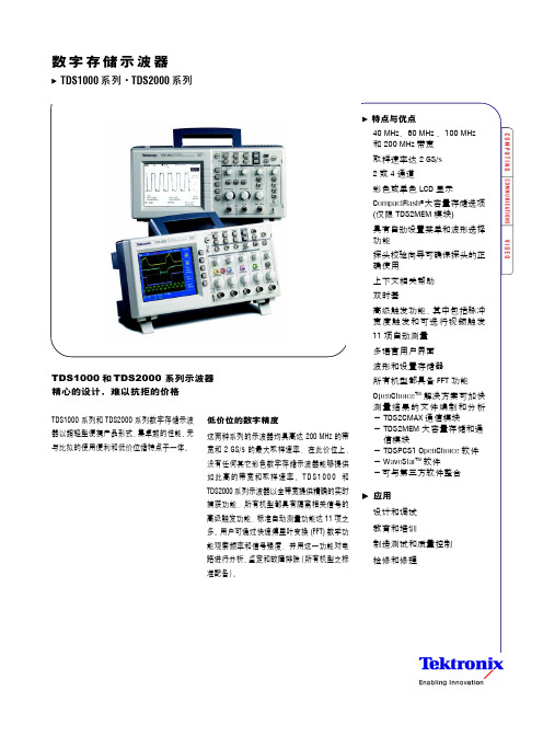
数字存储示波器系列·系列和TDS2000 系列示波器精心的设计,难以抗拒的价格TDS2000 系列数字存储示波低价位的数字精度数字存储示波器TDS1002系列·TDS2000系列2 TDS1000/TDS2000 系列示波器 /tds1000_2000脉冲宽度以及场选和行选视频触发功能使该 系列示波器适用于各种应用。
无与比拟的测量精度及高达 200 MHz 的带宽 和 2 GS/s 的最大取样速率。
自动检测正弦波、方波和视频信号,提供相 关测量读出值,用户可选择其它信号视图。
设置和使用易如反掌这些仪器具有古典的模拟式控制,用户界面非常简单,易于使用,不仅可减少学用时间,而且也提高了使用效率。
自动设置菜单、探头校验向导和上下文相关帮助以及彩色 LCD 显示(TDS2000 系列)等创新性功能,使仪器的设置和操作得以进一步的优化。
简单快捷的文件编制和分析功能OpenChoice TM 解决方案为示波器和个人计算机提供了既简单又全面的整合途径,使您可通过多种选择,轻而易举地编制测量报告和分析测量结果。
供选用的部件包括通信模块、CompactFlash ®大容量存储能力、OpenChoice 软件和第三方软件整合。
数字存储示波器TDS1002系列·TDS2000系列可迅速将波形和测量数据传送至外部 PC 机或在示波器之间快速传送。
只需按一下自动设置菜单上的按钮即可对电 路进行精确的分析、鉴定和故障排除。
通过 OpenChoice TM 软件轻而易举地编制测量结果文件并进行分析。
外部触发输入所有型号提供记录长度所有型号上2.5 K 样点垂直分辨率8位垂直灵敏度 在校准微调后,所有型号上2mV -5V/div DC 垂直精度所有型号上±3%垂直缩放 垂直扩展或压缩活动波形或已停止的波形最大输入电压 300 VRMS CAT II; 在超过100 kHz 时额定值以20 dB/10 Hz 下降,在3MHz 及以上时为13 Vp-pAC 位置范围 2mV -200 mV/div 2V; >200 mV -5V/div 50 V 带宽限制所有型号上20 MHz 输入耦合所有型号上AC, DC, GND输入阻抗1M Ω, 并联, 20 pF时基精度50 ppm水平缩放水平扩展或压缩活动波形或已停止的波形*1在2mV/div 时带宽为20 MHz, 适用于所有型号。
- 1、下载文档前请自行甄别文档内容的完整性,平台不提供额外的编辑、内容补充、找答案等附加服务。
- 2、"仅部分预览"的文档,不可在线预览部分如存在完整性等问题,可反馈申请退款(可完整预览的文档不适用该条件!)。
- 3、如文档侵犯您的权益,请联系客服反馈,我们会尽快为您处理(人工客服工作时间:9:00-18:30)。
目
录
目 录.............................................................................................................................................................. i 版权声明........................................................................................................................................................ iii 第 1 章 安全事项........................................................................................................................................... 1 1.1 常规安全事项概要..............................................................................................................................1 1.2 安全术语和符号..................................................................................................................................1 1.3 产品上的术语......................................................................................................................................2 1.4 产品上的符号......................................................................................................................................2 1.5 产品报废处理......................................................................................................................................2 第 2 章 概述................................................................................................................................................... 3 2.1 DSO5000 系列数字存储示波器简介................................................................................................ 3 2.2 帮助系统............................................................................................................................................. 3 第 3 章 操作入门........................................................................................................................................... 5 3.1 安装..................................................................................................................................................... 5 3.1.1 电源.............................................................................................................................................. 5 3.1.2 电源线.......................................................................................................................................... 5 3.2 功能检查............................................................................................................................................. 5 3.2.1 接通示波器电源.......................................................................................................................... 5 3.2.2 示波器接入信号.......................................................................................................................... 5 3.2.3 观察波形...................................................................................................................................... 6 3.3 探头检查............................................................................................................................................. 6 3.3.1 安全性.......................................................................................................................................... 6 3.3.2 使用检查向导检查电压探头...................................................................................................... 6 3.4 手动探头补偿......................................................................................................................................7 3.5 探头衰减设置......................................................................................................................................7 3.6 自校正................................................................................................................................................. 8 第 4 章 示波器主要功能介绍 ....................................................................................................................... 9 4.1 设置示波器..........................................................................................................................................9 4.2 触发..................................................................................................................................................... 9 4.3 采集数据........................................................................................................................................... 10 4.4 缩放和定位波形................................................................................................................................ 11 4.5 波形测量............................................................................................................................................11 第 5 章 基本操作.........................................................................................................................................13 5.1 显示区............................................................................................................................................... 13 5.1.1 XY 格式:...................................................................................................................................15 5.2 水平控制系统................................................................................................................................... 15 5.2.1 扫描模式显示(滚动模式).................................................................................................... 18 5.3 垂直控制........................................................................................................................................... 18 5.3.1 使用 FFT 观察时域波形........................................................................................................... 19 5.3.1.1 设置时域波形..................................................................................................................... 20 5.3.1.2 显示 FFT 谱....................................................................................................................... 21