测宽仪调试笔记
裂缝测宽仪操作规程
裂缝测宽仪操作规程
《裂缝测宽仪操作规程》
一、设备准备
1. 将裂缝测宽仪放置在平整的工作台上,确保周围无杂物。
2. 检查裂缝测宽仪的各个部件是否完好,有无损坏或缺失。
3. 准备好测宽仪需要使用的相关配件和标尺。
二、环境准备
1. 确保操作环境通风良好,避免有害气体的滞留。
2. 保持操作区域整洁,避免杂物干扰操作。
三、操作步骤
1. 将测宽仪平放于裂缝上,调整测宽仪的位置,使其与裂缝平行。
2. 使用调节螺丝来微调测宽仪的位置,直至完全贴合裂缝。
3. 用标尺测量裂缝的宽度,并记录下来。
4. 移动测宽仪至下一个位置,重复以上步骤,直至整个裂缝的宽度都被测量完毕。
5. 对测量结果进行整理和分析,制作裂缝宽度的测量报告。
四、注意事项
1. 在操作裂缝测宽仪时,要小心轻放,避免碰撞和摔落,导致仪器损坏。
2. 在测量裂缝宽度时,要确保测宽仪的位置准确,避免测量偏差。
3. 在测量结束后,要及时清洁和保养裂缝测宽仪,确保下次使
用时能够正常工作。
五、结束工作
1. 将裂缝测宽仪和配件整理好,放回指定位置。
2. 清理操作区域,将工作台和周围环境恢复整洁。
3. 对操作人员应进行操作规程的总结和评价,及时修正不足之处。
通过以上规程的操作,可以确保裂缝测宽仪的正常使用,提高测量的准确性和工作效率,保障施工质量和安全。
测宽仪操作说明
精轧测宽仪操作说明
针对近期测宽仪异常情况,电气人员操作不当,可能会发生系统崩溃等严重后果,为更好的保证设备正常使用,特作如下说明:1】定期检查测宽仪内部压缩空气吹扫情况,避免无压缩空气造成冬季水汽凝结在测宽仪测头的镜片上,造成不测量;
2】检查G辊道上吹到层冷水的压缩空气,避免由于测宽仪扫描不到带钢的边缘而报故障,不测量或者测量结果为直线;
3】出现测头无响应或者测量长度过长、过短等故障采用CPU板上的复位键对测头复位,检查是否正常;
4】认真检查仪表柜上的按钮位置以及指示灯状态是否正常;5】如果故障仍然存在,说明测宽仪信号本身没有问题,信号处理产生错误时,尝试重启电脑,必须按如下步骤操作:
A、按键盘上左下角ctrl以及右上角按键print screen,之后,
按回车enter;
B、出现login时,输入root,按回车enter;
C、出现#时,输入shutdown,按回车enter;
D、此时系统关闭画面应用程序自动重启。
二轧厂
2011-11-28。
测宽仪操作手册
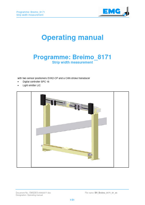
Operating manual Programme: Breimo_8171Strip width measurementwith two sensor positioners EVK2-CP and a CAN stroke transducer•Digital controller SPC 16•Light emitter LICRevision status: Name: Date:00 New formatting + safety precautions Roet 26 June 200701 Contents corrected (Machine/Component) Roet 21 Febr. 2008© 2008 EMG Automation GmbH. All rights reserved.The copyright of this document remains with EMG Automation GmbH. It contains information of a technical nature, which may not be copied whole or in part, published or utilised in an unauthorised manner for purposes of competition or communicated to others.Subject to technical alterationsTable of contents1Safety 5 1.1Introduction 5 1.2General regulations 5 1.3Non-compliance with the safety regulations 6 1.4Fundamental safety precautions 6 1.4.1Local legislation, directives and regulations 6 1.4.2Area of application 6 1.5Structure and meaning of the references 7 1.5.1Graphic reference symbols 8 1.6General safety regulations 9 1.6.1State of the art technology 9 1.6.2Removal of safety guards 10 1.7Specific safety regulations 11 1.7.1Mechanical dangers 11 1.7.2Electrical dangers 11 1.7.3Hydraulic dangers 11 1.8Responsibilities and qualification requirements 12 1.8.1Authorised personnel/Qualified employees 12 1.9Duty of notification in the case of malfunctions and damage 13 1.10Necessary protective clothing 13 1.11Prohibition of alterations and modifications 13 1.12Duty of maintenance 13 2Initial operation 14 2.1Parameterisation of control system with ECU 14 2.1.1Keyboard and display unit ECU 01 15 2.1.1.1Button functions of the green keypad (preselection of operating modes) 15 2.1.1.2Button functions of the blue keypad (entry of parameters/selection of measured values)17 2.1.1.3Operation (examples) 19 2.1.1.4Control of operating modes 21 2.1.2PROFIBUS coupling system (master) - EMG (slave)/OPTION 22 2.1.2.1MCU 24.2 for the SPC 16 system 22 2.1.3CANopen coupling for EMG sensors 25 2.1.3.1Cable type, cable length and wiring 25 2.1.3.2Terminal resistance 120 Ohm at CAN-Bus 26 2.1.3.3User address at CAN-Bus 26 2.2Adjusting the operating modes using ECU 01 27 2.2.1Basic settings for optical measuring equipment EVK2-CP 292.2.2Entering the measuring range of the photocell 35 2.2.3Setting the stroke for the EVK 36 2.2.4Operating mode "Automatic" (Strip width measurement ON) 38 2.2.5Adjustment for EVK activation (search edge) 38 2.2.6Adjusting the strip width output 39 2.2.7Calibration mode of strip width measurement using EMG calibration sheet 40 2.3Signal exchange via POTENTIAL-FREE CONTACTS 42 2.4Signal exchange via PROFIBUS-DP 423Troubleshooting for standard programme 43 4Appendix 45 4.1Adresses and settings of DIL-Switches 45 4.2List of parameters – Selection using the ECU 01 keyboard 46 4.3List of measured values – Selection using the ECU 01 keyboard 47 4.4List of PROFIBUS-DP interface 501 Safety1.1 IntroductionThis chapter explains the safety regulations that must be strictly observed when usingthis plant. It defines the responsibilities of the operator and the safety information thatcall attention to the various danger levels in the individual chapters.WARNINGDeath or serious bodily injury.As a result of inappropriate action undertaken with components of the plant.The chapter entitled "Safety" must by read and fully understood by all persons who areresponsible for operation, maintenance or repair work.1.2 General regulationsThe person responsible for the plant must ensure that• safety information and operating instructions are available and observed• operating conditions and technical data are observed, in accordance with the order• safety guards are used• prescribed maintenance work is carried out• maintenance personnel are informed without delay or the electrical component is stopped immediately if abnormal voltages, high temperatures, noises, vibrations etc.occur in order to determine the cause.This operating manual contains the information which is required for qualified personnelto utilise the strip control systems in industrial plants. Additional information andreferences for non-qualified persons and for using the components innon-industrial plants are not contained in this operating manual.The manufacturer's guarantee only applies if all operating instructions are adhered to.1.3 Non-compliance with the safety regulationsEMG Automation GmbH accepts no responsibility for any damage which results fromnon-compliance with the instructions and information contained in the operating manual.This particularly applies to damage:• caused by improper use or through faulty operation.• caused by ignoring the safety information contained in the operating manual.• caused by unsatisfactory or non-implemented maintenance and repair work.• caused by incorrect selection of the workpieces or tools.1.4 Fundamental safety precautions• Only authorised personnel may work with components of the plant.• The strip guiding system may only be operated in perfect condition whilst complying with the operating manual and operating instructions.• Any mode of operation that endangers the safety of persons or impairs the safety of the strip guiding system must be prohibited.• All maintenance and repair work should only be implemented in principle when the plant is at a complete standstill.• The manufacturer must always be contacted in case of doubt.1.4.1 Local legislation, directives and regulationsThe general applicable national and local safety and accident prevention laws as well asoperator regulations are to be adhered to in addition to this operating manual.1.4.2 Area of applicationThe details, instructions and safety-relevant information contained in this manualexclusively apply to the present control system.1.5Structure and meaning of the referencesStrip guiding systems are electric control systems according to the state of the art for use in industrial plants that are safe to operate.Safety regulations prevent injury to persons and material damage.Important instructions concerning technical and industrial safety are specially emphasised in the technical documentation as follows:Refers to a dangerous situation which results in death or serious bodily injury.WARNINGRefers to a dangerous situation which can result in death or serious bodily injury.CAUTIONRefers to a potentially dangerous situation which can result in minor to medium bodily injury.Refers to a situation which can result in damage to property.For application information and other useful information (tips & tricks).1.5.1Graphic reference symbolsThese symbols can be found in various places in the operating manual, in the instruction manual and on the component itself. These signs must always be observed!The symbols (pictograms), warning- and information signs have the following meaning:120-0001120-0002120-0003120-0004Caution! Electric shock Caution! Hot surfaceCaution! Danger ofexplosionCaution! Hand injury120-0005120-0006120-0007120-0008Caution! Laser beam Caution! Rotating gears General hazard warningCaution! Risk ofcrushing120-0009120-0010120-0011120-0012Caution! Risk of fireCaution! Suspendedload Wear a helmetWear ear and eyeprotection120-0013120-0014Wear protective goggles!Wear gloves!1.6 General safety regulations1.6.1 State of the art technologyThe entire system corresponds to state of the art technology and the recognised safetyregulations. The construction of the system is based on the following guidelines andstandards.EN 12100-1/-2 Safety of machineryEN 294 Safety distances to prevent danger zones being reachedEN 349 Safety of machinery; minimum gaps to avoid crushing of partsof the human bodyEN 414 Rules for the drafting and presentation of safety standardsEN 418 Emergency stop equipment, functional aspects; principles fordesignEN 547-1 Human body measurements - principles for determiningdimensions, access openings etc.EN 614-1 Ergonomic design principlesEN 811 Safety distances to prevent danger zones being reachedEN 953 Safety guardsEN 954-1 Safety-related parts of control systemsEN 982 Safety requirements for fluid power systems and theircomponents - hydraulicsEN 983 Safety requirements for fluid power systems and theircomponents - pneumaticsEN 999 The positioning of protective equipment in respect of approachspeeds of parts of the human body.EN 1037 Avoidance of unexpected startEN 1050 Principles for risk assessmentEN 1088 Interlocking devices associated with guards - principles fordesign and selectionEN 1127-1 Explosion prevention and protectionEN 50178 Electronic equipment for use in power installationsEN 60204-1 Electrical equipment of machinesEN 61000-6-2 Electromagnetic compatibility (EMC)Risks and residual danger to life and limb still exist, particularly if the plant's componentsare not operated in accordance with the specifications and regulations or if they areoperated by unauthorised personnel [see "Authorised personnel and responsibilities"].1.6.2 Removal of safety guardsSafety guards and covers may only be removed if plant is electrically disconnected andstopped. The safety guards and covers in particular may only be removed by authorisedpersons and must be reassembled before restarting the system.WARNINGSerious bodily injury or deathCaused by unauthorised access.When conducting maintenance work a safety fence is to be set up which prevents access to unauthorised persons.1.7 Specific safety regulationsWhen conducting any setting, maintenance and repair work on the plant it is imperativethat the switch-off procedures described in the respective chapters of the operatingmanuals are observed.1.7.1 Mechanical dangersWARNINGCutting injuries and crushing of body partsCaused by sharp edges and moving parts.Wear protective clothing and do not enter into the effective range of the plant'scomponents.1.7.2 Electrical dangersDeath due to electric shockHigh voltages develop.Circuit components may only be accessed by trained personnel using ESD-protectivemeasures.1.7.3 Hydraulic dangersCAUTIONMinor bodily injuriesCaused by squirting oil.It must be ensured that the hydraulic system is depressurised before any maintenanceor repair work is started.• Do not change the pump pressure specified in the hydraulic plan and in theinstruction manual.• Regulating valves that are sealed or secured in another way may not be adjusted.• When conducting any work on the hydraulic system (e.g. replacing the hydraulic hoses) prepare containers and collecting pans to catch any hydraulic oil that drips orleaks.• The hydraulic oil that has been replaced is to be filled into appropriate refusecontainers and disposed of in accordance with environmental-protection regulations.1.8 Responsibilities and qualification requirementsThe responsibilities for the different activities must be clearly specified and maintainedby the operator of the plant in order to prevent any ambiguities arising under the aspectof safety.Dangers can arise from the components of the plant if they are improperly fitted. Thisapplies particularly to work on the electrical/electronic and hydraulic equipment (see"Product specific dangers and danger areas"). The operator must make sure that onlytrained persons work on the plant or stay in the danger area.1.8.1 Authorised personnel/Qualified employeesDeath, serious bodily injuries, damage to property.Caused by persons who not authorised to work on the plant.Therefore work may only be implemented by authorised persons. Authorised personssatisfy minimum training and knowledge requirements and have achieved a preciselydefined level of expertise.The supplied equipment may only be transported, installed, connected, put intooperation, maintained and operated by qualified personnel that have mastered thecurrent safety regulations and mounting instructions. All work must be checked byresponsible qualified personnel. The qualified personnel must be authorised to do thenecessary work by the person legally responsible for the safety of the plant.Qualified persons are those who:• have the training and experience• know the current respective standards, specifications, regulations and accident prevention guidelines• have been trained and are fully familiar with the functionality and operationalconditions of the system• are able to detect and prevent dangersFor regulations and definitions concerning qualified personnel, see VDE 0105 or IEC 364.The appropriately trained personnel may only work within the scope of their professional training.1.9 Duty of notification in the case of malfunctions and damageThe plant operator is obligated to examine the components of the plant at least once pershift for any signs of externally visible damage or malfunction.Any changes (including the operational behaviour), which can impair safety must beannounced immediately.1.10 Necessary protective clothingWhere required the operating company must enforce the use of protective clothing,gloves, goggles etc. by operating personnel.1.11 Prohibition of alterations and modificationsWARNINGDeath or serious bodily injuryCaused by defective and/or missing safety equipment.In principle no safety equipment may be disassembled or decommissioned (except inthe event of maintenance and repair work)!Any kind of alterations and modifications to the components are strictly prohibited forsafety reasons!Only spare parts and accessories which are approved by EMG, or parts whichcorrespond to the original condition are to be used!1.12 Duty of maintenanceThe operator of the plant is obligated to use it solely in a perfect and undamagedcondition. Maintenance and repair work is described in the instruction manuals.• Any traces of oil are to be eliminated immediately.• Only original spare parts may be used.• After disassembling casing components or after conducting electricity installation work the assigned protective measures are to be inspected with regard to theircorrect functionality before restarting the plant.• A functionality or operational examination must be conducted in the setup operation in each case before restarting the plant.2 Initial operationBasic setting of parameters using the keyboard and display unit ECU 01The basic factory setting can be found as a printout of parameter file MCU 24 PRMunder chapter «Adjusting the operating modes using ECU 01» of these instructions.All control directions and parameters are set during the initial operation. These do notnormally need to be changed and should be entered in the list of parameters (appendix).If, however, an adjustment is deemed necessary (e.g., in the case of replacing or re-adjusting individual components), the parameter concerned can be called up and alteredusing the ECU 01 display unit.It is strongly recommended to note and document the current parameter settings.2.1 Parameterisation of control system with ECUThe display has four lines. Two measured values, two parameters or one measuredvalue and one parameter can be displayed at the same time.M = Prefix measured value of process variable, followed by 3 digits(e.g., M001 = measured value 1)P = Prefix parameter value of process variable, followed by 3 digits(e.g. P001 = parameter 1)2.1.1Keyboard and display unit ECU 01Membrane keyboard ECU 01010-00012.1.1.1Button functions of the green keypad (preselection of operating modes)Key Meaning EXTERN010-0025_Key with LEDWhen the EXTERN LED is lighted, the mode selector keys are locked.By actuating the EXTERN key, the mode selector keys are released. AUTOMATIC010-0027Key with LEDThe LED indicates that the automatic mode is active.If the EXTERN LED is not lighted, the automatic mode is activated using the AUTO key.MANUAL010-0026Key with LEDThe LED indicates whether the manual mode has been selected. If the EXTERN LED is not lighted, the manual mode is activated using the MANUAL key. MANUAL →010-0030ButtonThe MANUAL → key is released if the EXTERN LED is not lighted and the MANUAL LED is lighted. By actuating the MANUAL → key the drive is moved at a selectable speed.Key Meaning MANUAL ←010-0029ButtonThe MANUAL key ← is released if the EXTERN LED is not illuminated and the MANUAL LED is illuminated. By actuating the MANUAL ← key the drive is moved at a selectable speed.CENTRE010-0028Key with LEDThe LED flashes if the centre has been selected. It is permanently illuminated when the centre position has been reached.Once the EXTERN LED does not light, the "drive centre position" function is activated using the CENTRE key.2.1.1.2Button functions of the blue keypad (entry of parameters/selection of measured values)Button or button combination Meaning+ or ↑010-0021– Changeover to standard display (only from the basicmask) – Increment mask number (standard display)– Increment value of current variable or mask number(entry mode) – Set current variable to 1-signal (entry mode, bitvariable)- or ↓010-0022– Decrement mask number (standard display) – Decrement value of current variable or masknumber (entry mode)– Set current variable to 0-signal (entry mode, bitvariable) →010-0024– Change active mask (toggle, standard display) – Cursor right (entry parameter, mask number)←010-0023– Change displayed values/parameters of active mask(toggle) – Cursor left (entry parameter, mask number)ENTER010-0020– Completion of entry or acceptance of modifiedvalues/settingsESC010-0019– Abnormal termination of function – Return to previous levelButton or buttoncombination Meaning010-0018String of mode keys:Selection of interface (RS 232/RS 422)Status ECU 01 (including selected language)Status programme controller (basic mask) (combinations not shown are not used)010-0017String of function keys:Release entry mode (password to change parameters)Select entry mode (change of parameters)Activate mask number entryReload old value (combinations not shown are not used)The blue keypad is reserved for operating the 4-line LCD display.2.1.1.3 Operation (examples)Display measuring point M001 (strip width)•Press the ENTER button• Actuate the "<" button once or twice until measuring point M0xx isdisplayed.• Actuate the "+" or "-" button until measuring point M001 is displayed.Change parameter P006 (trigger final position EVK 1 inside)•Press the ENTER button•Actuate the "<" button once or twice until parameter P0xx is displayed.• Actuate the "+" or "-" button until parameter P006 is displayed.• Actuate the button sequence"F" + ">" + "M" + "F" + "ENTER"The cursor flashes at the first position(sign).• Use the cursor button "<" or ">" to move the cursor to the digitto be changed.• Alter the value using the "+" or "-" buttonsAlter all digits if required• Use the cursor button "<" or ">" to move the cursor to the nextdigit to be changed.• Alter the value using the "+" or "-" buttonsAlter all other digits if required• Now confirm by pressing "Enter".The parameters to be entered are checked for limit values.If the entered value is above or below the limit value (upper or lower limit), the change is ignored.M001 strip width +1023.0 mmP006 final position EVK 1 inside +5.0 mm2.1.1.4 Control of operating modesThe system offers the following possibilities of changing the operating mode (auto,manual, centre):1. Internal control using ECU 01 keypad2. External control using digital inputs3. External control via PROFIBUS, in connection with central unit MCU 24.2 (option)to 1:(EXTERN LED does not illuminate), then the operating modes arespecified via the green button field of the ECU 01 keypad.The mode which was previously activated using the external control orPROFIBUS persists.to 2 and 3: Array When selecting external control via the "EXTERN" button (EXTERN LEDilluminates), it is possible to control the unit via digital inputs orPROFIBUS-DP.The control via PROFIBUS-DP is released by ECU 01 using the parameter P001.P001 Bit "1" = release: Operating modes are controlled via PROFIBUS.P001 Bit "0" = lock: Operating modes can not be controlled via PROFIBUS-DP.The external control using digital inputs is released by parameter P017.P017 Bit "1" = release: Operating modes are controlled via digital inputs.P017 Bit "0" = lock: Operating modes can not be controlled via digital inputs.If both parameters are set to Bit "1", then PROFIBUS is selected in the programme.2.1.2 PROFIBUS coupling system (master) - EMG (slave)/OPTION2.1.2.1 MCU 24.2 for the SPC 16 systemMCU 24.2 with its X4 interface serves for the communication with a higher-level systemcomputer as a SLAVE in PROFIBUS-DP.The system master data file of MCU 24.2 (HMS_1003.GSD) contains the systemparameters required for the PROFIBUS-DP MASTER. It is available to download fromthe EMG homepage at .• Servo-Technique Metal• Downl. Service• Software• PROFIBUS Servo-Technique• Download the files as described.When planning the master system, the following points must be observed:• Paste the GSD file into the \\..\gsd directory.• MCU 24.2 can be found in the network configurator of the PROFIBUS system under the column OTHER FIELD SYSTEMS\GENERAL\ANYBUS_HMS...• MCU 24.2 only operates in a Word oriented manner.• All words must be individually projected (max. 62 data words per data direction).• The number of words to be projected in the PROFIBUS-DP master system must be in line with the number of words in MCU 24.2.• In the communication with Siemens S7 the HIGH byte and the LOW byte areinterchanged in S7.• Before transmitting control signals (individual bits within a word), HIGH byte and LOW byte must be interchanged in the S7 software.• The command is: TAW (in the accumulator)The front panel of MCU 24.2 has 4 additional LEDs to signal the status on the PROFIBUS-DP:LED Position MeaningH3 Error LED PROFIBUS side:OFF no error detected on PROFIBUS sidered, flashing 1 Hz Error in configuration:Data length send/receive at initialisation different fromdata length in network configurationred, flashing 2 Hz Error in user parameter data:Data length at initialisation different from data length innetwork configurationred, flashing 4 Hz Error in initialisation PROFIBUS-ASIC SPC 3H4 not usedH5 red, illuminatedOFF PROFIBUS module offline, no data exchange possible PROFIBUS module not offlineH6 green, illuminatedOFF PROFIBUS module is online, data exchange is possible PROFIBUS module is not onlinePROFIBUS-DP user addressThe rotary DIL switches S3 (LOW byte) and S4 (HIGH byte) determine the user address in decimal coding. The highest user address is 99. After restarting the supply voltage to MCU 24, the new address is accepted.Example: user 7 : S3 = 7 and S4 = 0user 17 : S3 = 7 and S4 = 1;The PROFIBUS connection is designed as a 9 pole D-Sub connector (X4).X4 PROFIBUS-DP, D-Sub connector, 9 poleX4.1 N.C.X4.2 N.C.X4.3 B-Line Rx+, Tx+X4.4 RTS Request to Send 1*X4.5 GND Insulated GND towards RS 485 side 1*X4.6 +5 V Insulated +5 V towards RS 485 side 1*X4.7 N.C.X4.8 A-Line RX-, Tx-X4.9 N.C.1*): Signals for additional functions, not connected in normal operation!050-0005S3 Address PROFIBUS-DP (100)X1 RS 232/download and onlinetestX2 CANopen for EMG sensors S4 Address PROFIBUS-DP (101)X3 RS 232 for ECU 01 H1 Flashing cycleX4 PROFIBUS-DP field bus H2 Operational (continuous light)Error CANopen (flashing light)S1 Initial start H3 .. H6 Messages PROFIBUS-DPS2 DownloadThe following table provides a description of the operating elements of the MCU 24.2 PROFIBUS-DP interface:Switch, LED Position MeaningS3 0 .. 9 Address setting PROFIBUS 0 .. 9S4 0 .. 9 Address setting PROFIBUS 1x .. 9x (see S3)2.1.3 CANopen coupling for EMG sensorsThe optical and inductive EMG sensors are connected to the central unit via the CAN-Bus. Communication is stable in all operating modes if the following major basicconditions are complied with:Communication data• Baud rate = 250 kBaud/max. cable length 160 m• Max. No. of users = 122.1.3.1 Cable type, cable length and wiringThe following cables comply with this specification:Make Lapp• Unitronic Bus LD (2 x 2 x 0.22)(EMG standard cable for RS 485, CAN-Bus) EMG part No.: 181948• Unitronic Bus Device Net(OVDA Device Net; industrial standard: max. 2 wire pairs)• Unitronic Bus CAN (max. 2 wire pairs)Specifications:Characteristic impedance: 120 ΩOperating capacity: max. 60 nF/1000 m (800 Hz)Wire cross section: min. 0.22 mm²/wire (<AWG24)No. of wires:Wires stranded in pairs:pair 1..3 (P1..P3)P1: CAN_H/L and P2: 24 V/GND 3x2 (P1:CAN_H/L,P2: 24 V/GND)2x2 (P1:CAN_H/L,P2: 24 V/GND) potential-free CAN-Bus1x2 (P1: CAN_H/L) potential-free CAN-BusTemperature range: -40....+ 80 °CMax. cable length160 metres for baud rate of 250 kBaud.WiringThe signals "CAN-high" and "CAN-low" must be transmitted in one pair of wires. The CANopen network must be wired according to the applicable circuit diagram.2.1.3.2 Terminal resistance 120 Ohm at CAN-BusA terminating resistor must be provided at the end of the bus line (first and last user).The EMG sensors and EMG central units have an integral terminal resistance whichmust be activated by a jumper.• Inductive sensors = Jumper J9• Optical sensors EVK/EVM = Jumper J9• Digital stroke sensors = firmly soldered to 2nd connector• CCD camera = DIL switch S422.1.3.3 User address at CAN-BusThe CAN-Bus master (EMG central unit) address is 1 (firmly set for each programme).The addresses of the other users (slaves) are selected on the equipment using therespective DIL switch.• Inductive sensors = Addr. 2 and 3/DIL switch S50/S51• Optical sensors EVK/EVM = Addr. 4 and 5/DIL switch S50/S51• Digital stroke sensors = Addr. 6 and 7/handheld• CCD camera = Addr. 8 and 9/DIL switch S412.2 Adjusting the operating modes using ECU 01CAUTIONRisk of injuryCaused by moving parts.Check whether the actuator can be moved with no risk.• The lists of parameters, measuring points and PROFIBUS signals (option) can be found in the appendix.• Furthermore, the appendix contains a list of addresses and DIL switch settings of controller SPC 16.• +4095 or -4096 digit are maximum values for +10 V DC or -10 V DC, relating to a 12 bit resolution of the AD/DA converter.Switch ECU 01 to INTERN (LED in EXTERN button does not illuminate).Content of parameter file MCU 24.PRM (basic factory setting)The following settings are standard settings and serve as starting values to commission the application.。
DJCK-2裂缝测宽仪操作规程

DJCK-2裂缝测宽仪操作规程
一、使用方法
1.裂缝宽度测量:用电缆连接显示屏和测量探头,打开电源开关,将测量探头的两支脚放置在裂缝上,在显示屏上可看到被放大的裂缝图像,稍微转动摄像头使裂缝图像与刻度尺垂直,根据裂缝图像所占刻度线长度,读取裂缝宽度值(见图2)。
图2 裂缝宽度测量示意图
2.仪器校验:校验标准刻度板上分别有宽度为0.02、0.10、0.20和1.00mm的刻度线。
分别把摄像测量头支脚放在不同宽度的刻度线上,屏幕上读取相应的刻度线宽度。
当误差小于0.02mm时,仪器方可正常使用。
二、注意事项
1. 使用前应先进行校验,校验正常后,再使用;
2. 校验时,误差超过0.02mm时,请将仪器送回厂家校验维修。
3. 摄像镜头:可用橡皮囊吹或用软毛刷进行清洁;
4. 用后应及时充电,长期不用每月应充电一次。
5. 连接测量探头的插头为自锁式插头,插连线时将信号线插头的红点与探头的红点对齐后插入即可,拔下时用手捏住插头根部的螺纹处直接拔出。
切勿左右旋转或用力拉线,以免造成探头内部线路损坏。
五、故障排除
1. 按下电源,屏幕无显示:①检查连线是否连接好;②电池是否充足电。
2. 观测裂缝时,边缘图像模糊,检查被测裂缝表面是否高低不平,调整测量探头使之垂直于裂缝。
3. 校验时,刻度线边界模糊:检查校验板是否为正面朝上。
如有侵权请联系告知删除,感谢你们的配合!。
DJCK-3全自动裂缝测宽仪使用指导书

DJCK-3全自动裂缝测宽仪使用指导书目录§1概述 (1)§1.1仪器组成和主机键盘说明 (1)§1.2主要技术指标 (1)§1.3工作原理 (2)§1.4主机界面介绍 (2)§2使用方法 (7)§2.1仪器键盘测量 (7)§2.2使用触摸屏测量 (7)§3传输数据到计算机 (8)§4校正液晶屏 (9)§5输入法的使用 (11)§6注意事项 (12)§7故障排除 (12)§8裂缝测宽仪数据处理软件V1.0 使用说明 (13)§8.1安装 (13)§8.2此软件的使用 (17)§1概述DJCK-3全自动裂缝测宽仪,主要用于测量建筑物的结构裂缝,结构裂缝是影响建筑物安全的重要因素之一,及时发现和准确测量裂缝是工程检测中一项不可或缺的工作,也是采取修补加固措施的重要前期工作。
§1.1仪器组成和主机键盘说明裂缝测宽仪由主机﹑摄像头﹑连接线﹑充电器﹑连接杆等部件组成。
图1-1 仪器基本组成§1.2主要技术指标放大倍数:18倍测量范围:0.10mm-4mm准确度:±0.02mm使用电压:4.2V锂电尺寸:126mm×150mm§1.3工作原理仪器将视频采集的数据存储在存储器中,通过对数据进行处理,计算裂缝宽度。
§1.4主机界面介绍打开电源,仪器启动,大约5秒后进入主界面,显示“测宽”和“校正”两个图标。
如图1-2。
图1-2 仪器界面“测宽”是裂缝测宽仪的测量。
“校正”是液晶屏的校正。
使用触摸笔点击图标,进入裂缝测宽仪软件界面如图1-3所示:软件主界面分为“Capture”,“Database”,“Setup”,“Camera”,“About”,等标签页。
§1.4.1. Capture:显示视频采集画面图1-3 Capture点击“Preview”按钮开始采集视频数据并以全屏的形式显示在屏幕上。
CKY-1测宽仪使用说明书

CKY-1测宽仪使用说明书1 概述由航天工业总公司第204研究所与天津赛象有限公司合作开发的测宽仪,具有测量速度快、精度高、稳定可靠、操作简便等特点,适用于各种带状物料的动态测量,并可实现自动检测与分类。
如将测量值送入计算机系统,进行计算处理,在通过执行机构实施控制,可组成一个闭环控制系统,实现物料宽度大小的精确控制。
2 组成由白色的荧光灯源,照相机镜头,线阵CCD驱动板及显示控制仪等组成。
3 主要技术指标1 分辨率为2592个象元,测量精度为0.5MM。
2 采样速度为50次/秒。
3 可测单条物料的宽度也可同时测两条物料的宽度。
4 具有并行接口,可给计算机系统并行传送四位BCD码。
5 具有串行接口,可实现RS232或RS422异步通讯。
6 可输出上超差、上限、标准、下限、下超差五个检测信号,实现自动检测与分类。
7 检测控制值由面板键盘设定。
4 信号与连接1 并行接口:有2路4位BCD码输出口,分别对应两条测量的宽度值,每条信号的连接如图所示。
1.2.3.4号最低位,5-8次低位,9-12次高位,13.25.24.23最高位,14-17(+24v),18-21(-24v)。
2 检测信号输出口:有两路光信号输出口,分别对应两条物料,每路由五个检测信号输出,可直接驱动五色灯,也可驱动五个直流24V继电器,驱动电流每一个输出不大于100MA。
5 仪表的调整仪表与系统初次接触,需进行全面的设定操作具体步骤如下:1 按住“设定”键,接通AC220V电源,左显示屏显示AAAAAA(按设定键,左侧显示屏显示COP0 或COP1 设定是否要加补偿,0 不加补偿,1 需加补偿,可按△键选择)。
2 按“设定”键左显示屏显示NUS1或NUS2其中最低位闪烁,设定测量条数,按△键可在1和2 间选择转换。
3 条数选定后,按“设定”键,如选择测量一条,则左显示屏显示读数,如测量两条,则左右显示屏均显示读数。
4 去除光源上的当光物,调节照相机镜头光圈,焦距及与光源的垂直水平位置,使读数显示为零或极接近为零。
测量放大器调整

测量放大器的安装与使用注意事项 page 1 of 1
ABB 组件 ABB 测量放大器的调整
参见图1,2
检查电动机构输出信号:分接开关电动机构的X7/1、2是测量放大器的电源进线;X7/3、4端子的直流输出电流,测量其输出:在最小档为4mA,最大档20mA,
其允许偏差为1%。
如不对,调节
电动机构箱内的测量放大器
(U1),在最小档(第1档)和最
大档分别调整。
测量时远显要从
回路中脱开。
如不符,先在最小
档调节“Zero adj.”调节螺钉,
使测量值为4mA,在最大档调节
“Max adj.”调节螺钉,使测量
值为20mA。
为保证准确性,应分
别在最大与最小档再校正一下。
对于有些测量放大器,移去前面板后,不一定如图2所示,但零位调节螺钉与最大位调节螺钉肯定是有的,调整方法相同。
如现场没有电流表,可连上调整过的远显表来调节。
拔出两个固定螺定, 移去前面板 图1 测量放大器 Zero adj. 零位调节螺钉 Max adj. 最大位调节螺钉 输出范围设定开关。
对应4-20mA 输出, 1-4位位于“On”(左边), 5、6位位于“Off”(右边)。
图2 测量放大器(移去面板)。
多功能智能裂缝测宽仪安全操作及保养规程

多功能智能裂缝测宽仪安全操作及保养规程1. 引言多功能智能裂缝测宽仪是一种用于测量建筑物、桥梁、道路等结构上的裂缝宽度的设备。
本文档旨在介绍多功能智能裂缝测宽仪的安全操作及保养规程,以确保设备的正常运行和使用者的安全。
2. 安全操作规程在使用多功能智能裂缝测宽仪之前,请务必仔细阅读并遵守以下操作规程:2.1. 设备检查在使用多功能智能裂缝测宽仪之前,必须进行设备检查,以确保设备的完好无损。
具体操作步骤如下:•检查设备外观是否有明显的损坏,如裂纹、变形等。
•检查设备是否有缺损,如按钮松动、连接线松散等。
•确保设备电源正常,电池电量充足。
2.2. 安全操作注意事项•在使用多功能智能裂缝测宽仪时,请确保操作者具备相关操作技能和知识。
•操作者应全程佩戴个人防护装备,如手套、护目镜等。
•在使用多功能智能裂缝测宽仪时,应保持设备表面干燥,避免接触液体或湿度过高的环境。
•避免长时间连续使用多功能智能裂缝测宽仪,以免设备过热。
2.3. 使用步骤使用多功能智能裂缝测宽仪的步骤如下:1.打开设备电源,确保电池电量充足。
2.将测宽仪放置在需要测量的裂缝上,并调整仪器位置,使其与裂缝平行。
3.按下测量按钮,仪器将自动测量裂缝的宽度。
4.读取测量结果,并记录或保存数据。
5.关闭设备电源,进行下一次测量或保养工作。
3. 保养规程为了保证多功能智能裂缝测宽仪的正常运行和延长设备的使用寿命,应遵循以下保养规程:1.定期清洁设备外观和传感器部分,避免灰尘和污垢积累影响测量准确性。
2.注意保护设备免受撞击和振动,避免设备损坏。
3.避免长时间暴露在高温、潮湿或强烈的阳光下,以防设备受损。
4.定期检查设备连接线是否松动,如有松动应及时进行固定。
5.如果设备出现故障或异常,请立即停止使用,并寻求专业人员进行维修或更换。
结论本文档详细介绍了多功能智能裂缝测宽仪的安全操作及保养规程。
使用者在使用设备时应严格按照操作规程操作,以确保安全和准确的测量结果。
- 1、下载文档前请自行甄别文档内容的完整性,平台不提供额外的编辑、内容补充、找答案等附加服务。
- 2、"仅部分预览"的文档,不可在线预览部分如存在完整性等问题,可反馈申请退款(可完整预览的文档不适用该条件!)。
- 3、如文档侵犯您的权益,请联系客服反馈,我们会尽快为您处理(人工客服工作时间:9:00-18:30)。
测宽仪调试
调试时间:2014/01/08至2014/01/09
调试内容:测宽仪标定、软件的操作使用及简单的故障维护。
一、大连亚泰华WG2000测宽仪
大连亚泰华光电技术有限公司成立于2004年,依托于大连理工大学光电检测技术工业中心与大连理工大学国家一级学科博士点—光电工程专业,具有一流的技术开发实力及十余年的测宽仪研究与开发经验。
1.1主要技术指标
测量精度:±0.4mm(动态);±0.2mm(静态)
测量范围:100~3500mm(可分档)
输出频率:100~200次/秒(5~10ms)
带钢温度:650~1300℃利用红外热辐射
<650℃利用上打光源照明
允许最大跳起:在摄像机的视场范围内
允许跑偏范围:在整个辊道范围内
1.2系统的工作原理与组成
1.2.1系统的工作原理
如右图所示,系统采用双摄像机利用立体视觉
原理和红外光电检测技术对辊道上的钢板进行在线
测量,并结合高速数字信号处理技术与编程软件相
结合对信号进行相应处理,并显示相关数据与测量
曲线。
1.2.2系统组成
WG2000测宽仪组成框图
调试步骤
1、安装好测宽仪主机、显示器、键盘、鼠标、显示输出接口模块等。
(零时接220V电源)*注意* 主机电源不能测头电源接一起,测头电源得单独供电。
显示输出接口模块直接连接在测头的RS422通讯发送接
口,可用于宽度偏差的记录或用于控制其他设备。
可以
输出以下信号:
• 正常信号(开关量)
• 有钢信号(开关量)
• 绝对宽度值(4~20mA)、或宽度偏差(-10V~10V)
• 中心位置偏差值(-10V~10V)
*记* 粗扎显示输出模块已坏,下次厂家来之前得提醒他
带一个过来。
2、检查线路是否正确(粗扎测宽仪其中操作台黑红绿白四根线顺序接错导致主机接收不到信号,经过校线故障解除。
)
3、显示器显示接收信号正常后开始对测宽仪进行标定。
标定
器用于对测宽仪进行标定,通过标定, 可自动确定测宽仪的系
统参数, 校正光学系统的非线性。
标定器上的标准板有多个
通光窗口,内部有可调模拟光源,可以模拟不同温度和不同
宽度的钢板。
标定时, 将标定器放置在辊道上, 启动自动标
定功能就可完成系统标定,确定并保存系统参数。
*注* (标定器正确放置方法:将标定器放在引风通道正下方,
且与轧制辊道平行,标定器中心与轧制中心重合。
放置正确
后保证其不能偏移。
)
图一 WG2000A/B 测宽仪的操作面画面主要由9个部分组成:1、待测栏:显示下一卷带钢的两个参数:钢卷号和设定宽度。
由轧线计算机在带钢到达F4时,通过串行口提供。
当与轧线计算机的通讯出现故障时,钢卷号和设定宽度也可以通过手工填入和修改。
2、当前栏:显示当前正在或已通过的最后一卷带钢的有关数据。
当带钢到达测宽仪时,测宽仪将‘待测’框中的钢卷号和设定宽度,锁定到‘当前’框中并一直保持,直到下一卷带钢到来时再锁定新值。
带钢的宽度瞬时值、最大值、最小值、平均值也在这一栏中实时显示’3、带钢数据列表:带钢数据表用来显示
“待测”栏“当前”栏信息提示
带钢数据列表历史纪录列表曲线显示窗口宽度及偏差“选项”栏
2、曲线显示窗口
宽度偏差曲线
报警上下界限
带钢中心位置
带钢跳动曲线
带钢温度曲线
故障状态提示
历史数据
在显示器上显示以下曲线:
宽度偏差曲线
粉红色为钢板宽度偏差曲线,显示钢板宽度测量值与设定值的差值,坐标显示范围可调。
移动鼠标可显示对应长度位置的宽度及宽度偏差。
可通过选项可选择显示冷态宽度或热态
宽度。
冷态和热态宽度转换
通过选项可选择显示冷态宽度或热态宽度。
宽度温度补偿采用测宽仪内部温度检测结果,
及普碳钢和低合金钢的温度系数。
显示宽度平均值、宽度最大值、宽度最小值
中心线偏差曲线
绿色为钢板中心线偏差曲线,用来显示钢板在辊道中的位置。
显示的数值是钢板两个边缘坐标的平均值。
显示范围可调。
两边缘位置曲线
深绿色为钢板两边缘位置曲线,用来显示钢板在辊道中的位置。
显示的数值是钢板两个边缘坐标的平均值。
显示范围可调。
温度曲线
黄色曲线为外部输入温度计钢板温度曲线,用来显示钢板中心温度分布,计算宽度温度修正量,据此决定钢板冷态宽度。
显示范围为可任意设定(如800~1200℃)。
查阅历史资料
利用WG-2000B软件可以方便的查阅历史记录。
当需要查看某一条带钢的宽度偏差曲线时可按以下步骤进行:
首先根据钢卷号判断生产日期
在历史记录列表中,用鼠标拖动滚动条,找到响应日期的记录。
用鼠标点击这个记录,这一天通过测宽仪的所有带钢,都会在带钢数据列表中显示出来
在带钢数据列表中,用鼠标拖动滚动条,查找响应的钢卷号,发现后点击该行,偏差曲线就会显示在曲线显示窗口中。
系统诊断操作界面
按‘诊断’按钮可进入测宽仪系统诊断功能操作界面,该界面主要用于系统故障分析、系统参数调整和系统标定等。
进入诊断程序后,测头将停止宽度测量,因此在正常运行期间不应随意进入。
此功能只能由维护人员进入操作,其他人员不得进入,以避免系统参数被修改,而导致系统无法正常工作。
诊断操作界面由五个部分组成:光强分布显示区,测头几何参数区、测头电气参数区2、程序参数区、提示信息区等几个部分组成。
光强分布显示区
显示两路线阵CCD摄像机的光强光强分布,红色对应1号摄像机(左侧),蓝色对应2号摄像机(右侧)。
“压缩显示”选项选中时,将5400像元的光强分布压缩在一个画面中显示。
“压缩显示”选项未选中时,可以看到每个像元的光强分布,整个画面只能显示约800个像元,是实际5400像元中的一小部分,需要通过拖动显示区域下方的滚动条,不同位置的光强分布。
测头几何参数区
测头几何参数区集中了和测头几何位置相关的各项参数。
“间距”: 两个摄像机之间的距离,单位是毫米(mm);
“高度”:摄像机镜头锁紧螺丝到标定器之间的距离,单位是毫米(mm);
“标定中心”: 标定器中心到测头对称轴线的距离,单位是毫米(mm);
“辊道中心”: 辊道中心到测头对称轴线的距离,单位是毫米(mm);
“辊道高度”: 辊道上面到标定器工作面的距离,单位是毫米(mm);
“标定器边缘数”: 标定时,所使用的标定器上的有效边缘数量;
“标定”按钮:确定标定器各边缘坐标位置;
“坐标”: 标定器上各边缘的位置,单位是毫米(mm);
“CCD1”: 第一路摄像机测得各边缘的像元位置,标定时,自动填入;“CCD2”: 第二路摄像机测得各边缘的像元位置,标定时,自动填入。
测头电气参数区
测头电气参数区集中了和测头电气设置相关的各项参数:
测头参数设定:
“增益”: 调整视频放大器增益,取值范围:0~64;
“偏置”:调整视频放大器电平,取值范围:-128~127;
“T(ms)”: 调整曝光时间,取值范围:0.8~20(ms);
“灰度阈值”: 光强灰度阈值,确定边缘位置用,取值范围:2000~8000;“梯度阈值”: 光强梯度阈值,确定边缘位置用,取值范围:200~2000;
测温设定:
“光强”: 选取规定的光强,取值范围:25000;
“温度”: 对应的钢板温度,700~1300
“波长”: 测温的中心波长,8500A;
测头DA输出设定:
“最大宽度”: 设置宽度输出模块的最大宽度;
“最小宽度”: 设置宽度输出模块的最小宽度;
“偏心最大”: 设置宽度输出模块的中心位置最大值;
“偏心最小”: 设置宽度输出模块的中心位置最小值;
按钮
“写测头参数”:将参数写入测头;
“读测头参数”:从测头读入参数;
“永久保存”:将测头参数写入非易失性存储器;
“测头复位”:对测头进行软复位。
程序参数区
测头参数设定:
“测头通讯端口”: 测头通讯端口号:1;
“文件路径”:数据文件路径;
显示曲线:显示曲线的坐标范围
“宽度最大”: 宽度偏差曲线坐标最大值;
“宽度最小”: 宽度偏差曲线坐标最小值;
“中心最大”: 中心位置曲线坐标最大值;
“中心最小”: 中心位置曲线坐标最小值;
“高度最大”: 高度位置曲线坐标最大值;
“高度最小”: 高度位置曲线坐标最小值;
“温度最大”: 温度位置曲线坐标最大值;
“温度最小”: 温度位置曲线坐标最小值;
CC D1为工作侧的摄像头,CCD2为驱动侧的摄像头,通过观察CCD 光强分布,可以判断出测宽仪光路中存在的问题。
按“读测头参数”按钮可将测头参数传回到主机上,并显示出来。
按‘“写测头参数”’按钮可将测头参数表中的数据传送给测头,测头将以新的设定参数工作。
如果确认当前测量参数工作正常,可按‘永久保存’按钮,将测头内部保存在静态存储器中的测头参数保存在非易失性存储器中,在断电后也不丢失。
CCD 光强分布窗口测头几何参数区测头电气参数区程序参数区提示信息区。