proe与ansys10.0之间的数据转换和连接
ProE与ANSYS接口
Pro/E和ANSYS的连接*作过程如下:1) 在同机的同一*作系统下安装有Pro/E和ANSYS两种软件;2) 保证上述两种软件的版本兼容,Pro/E的版本不得高于同期的ANSYS的版本;3) 开始->程序->ANSYS->ANS_ADSIN Utility->Configuration options-> Configuration Connection foràOK Pro/E->选择ANSYS Product->Work space inà选择Graphics device name(NT: Win32) 给出Language used withà给出Pro/Engineer installation pathàmegabytes(128) OK;àPro/Engineer:usascii4) 运行Pro/Engineer并配置config.pro;名称值说明fem_ansys_annotations yes 输出“模拟”分析名为ANSYS中的注释。
fem_ansys_grouping yes 切换组and/or层的转移到ANSYS。
fem_default_solver ANSYS 指定到一个求解器的路径。
fem_which_ansys_solver FRONTAL 允许指定使用Frontal ANSYS求解器还是Iterative ANSYS求解器。
femansys_annotations yes 切换载荷工况名称到ANSYS。
pro_ansys_path <路径名> 指定到可执行的ANSYS (ansys.e)的路径。
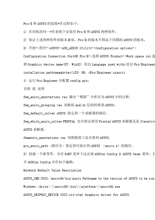
5) 创建一个新零件,并在PART菜单下这出现ANSCon Config & ANSYS Geom 菜单,打开ANSCon Config并作如下编辑;Keyword Default Value DescriptionANSYS_CMD UNIX:/ansys56/bin/ansys Pathname to the version of ANSYS to be run. Windows:<drive>:\\ansys56\\bin\\<platform>\\ansys56.exeANSYS_GRIPHIC_DEVICE UNIX:x11-stat Graphics driver for ANSYS.Windows:win32ANSYS_MEMORY_SIZE 128 Amount of RAM, in megabytes, suggested to run ANSYS. ANSYS_NEUTRAL_FORMAT YES Store the part as a neutral file or as a solid model file.ANSYS_PRODUCT_NAME ANSYS The default ANSYS product, ANSYS/Multiphysics. ANSYS_SOLVER Frontal Included for compatibility only.ANSYS_SELECTED_LAYERS 1-256 Included for compatibility only.ANSYS_GEOMETRY_TYPE Solids Only Included for compatibility only.补充一句,建议先打上nmsd.exe的补丁。
PROE与ANSYS之间的数据传递

随着计算机技术的不断发展,CAD/CAE技术在机械系统研究中的应用也越来越广泛。
PROE具有强大的实体建模能力,而ANSYS则具有强大的有限元分析计算能力,将PROE和ANSYS进行连接,综合利用它们各自领域的优势是机械系统研究的首选方案,这就涉及到PROE与ANSYS之间的数据传递。
目前,PROE与ANSYS之间的数据传递主要有以下几种方式。
1 利用IGES中间标准格式转换The Initial Graphics Exchange Specification(IGES)是由美国国家标准协会(ANSI)组织波音公司、通用电气公司等共同商议制定的信息交换标准,受到绝大多数CAD/CAM系统的支持。
但ANSYS在IGES 转换中,有时会把不能识别的特征省略掉,特别是模型特征过多或结构过于复杂时,很容易产生模型断裂、实体丢失等,直接影响有限元分析模型建模的准确性,此外,采用ANSYS进行IGES转换还具有耗时长的缺点。
2 利用ANSYS与PROE的专用接口转换ANSYS与PROE有一个专用接口模块“Connection for Pro/Engineer”,此模块不仅能将PROE模型数据快速准确地传递给ANSYS,还提供了以执行部件为基础的参数优化设计功能。
启动ANSYS路径下“ans_admin.exe”并在其中设置PROE的安装路径就能激活这个专用接口模块。
成功激活后可以在PROE主菜单栏中看到ANSYS对应版本的菜单。
利用专用接口转换进行数据传递有两种方式:在PROE环境下直接激活ANSYS或在ANSYS读取PROE模型文件。
2.1 在PROE环境下直接激活ANSYS在PROE环境下完成模型文件的创建后,直接点击主菜单栏上的ANSYS菜单,主菜单选择“ANSYS Geom”子菜单,将自动启动ANSYS应用程序并导入模型,同时PROE自动禁止用户交互,以保证数据一致性。
当ANSYS程序退出后,自动返回到PROE建模环境。
ANSYS与PROE、Creo的万能关联方法

ANSYS与PROE、Creo的万能关联方法ANSYS 与PROE 、Creo 的万能关联方法0 几点说明此方法适合于任何版本 ANSYS 与任何版本 Pro-E 、Creo 之间的关联ANSYS 与Pro-E 、Creo 之间的关联分为两步走:一、修改ANSYS 中的内容。
二、修改Pro-E 、Creo 中的配置文件config.pro 。
下面以ANSYS13.0与Pro-E5.0 M070之间的关联为例进行详解。
1修改ANSYS 中的内容1.1 打开D:\Program Files\ANSYS Inc\v130\aisol\CADIntegration\ProE\ProEPages\config (红色部分为您ANSYS 中config 的安装路径,安装路径因人而异,有的人安装路径为E:\ANSYS13.0\ANSYS Inc\v130\AISOL\CAD Integration\ProE\ProEPages\config )。
config 里面有config.pro 和WBPlugInPE.dat 两个文件,如图1所示。
图11.2 用记事本打开 WBPlugInPE.dat 。
1.3 用您自己ANSYS 的安装路径带替换以下红字部分代码。
(此处容易出错)NAME WB 130PluginProWF(您的ANSYS 版本是13.0此处就是130,如果您的ANSYS 版本是 12.0,12.1,14.0此次分别对应120,121,140,下同)EXEC_FILE D:\Program Files\ANSYSInc\v130\aisol\CADIntegration\ProE\intel\WBPlugInPECOM. dllTEXT_DIR D:\Program Files\ANSYSInc\v130\aisol\CADIntegration\ProE\ProEPages\Language\$ AWP_LOCALE130(同样,红色部分为您ANSYS 中WBPlugInPECOM.dll 、Language\$AWP_LOCALE130 的安装路径,注意后缀名) 用记事本打开WBPlugInPE.dat 将修改后的代码来替换前三句代码并保存,如图2所示。
proe与ansys转换

Pro/Engineer与ANSYS的数据交换1.常用交换方法(1)利用IGES中间标准格式转换。
由pro/engineer保存的IGES文件格式属于固定每行80字符的ASCII格式文件。
而ANASY本身内置了IGES转换过滤器,所以它支持IGES格式文件的导入。
但是转换过滤程序允许输入部分模型参数,所以ANSYS有时会把不能识别的特征省略掉。
当Pro/Engineer中建立的模型特征过多或结构过于复杂时,使用IGES文件格式输入到ANSYS后很可能产生模型断裂、丢失实体等情况,会直接影响模型后续分析的准确性。
(2)使用ANSYS—Pro/Engineer接口转换。
ANSYS软件安装选项中包含与Pro/Engineer软件的接口模块“Connection for Pro/Engineer”。
此模块不仅能将Pro/Engineer模型数据直接转换给ANSYS,同时还提供了以执行部件为基础的参数优化设计功能。
该功能允许从建立以部件为基础的参数化Pro/Enginee模型开始,用ANSYS程序对其进行优化,并以一个优化的模型结束,而且建立好的模型仍是以部件为基础的参数化模型。
此模块能给工程人员在有限元分析过程中考虑采用何种前后处理提供最好的支持。
利用软件自带接口能够快速准确地导入数据,ANSYS在默认状态无法识别Pro/Engineer中的prt文件,以下就是具体的配置方案。
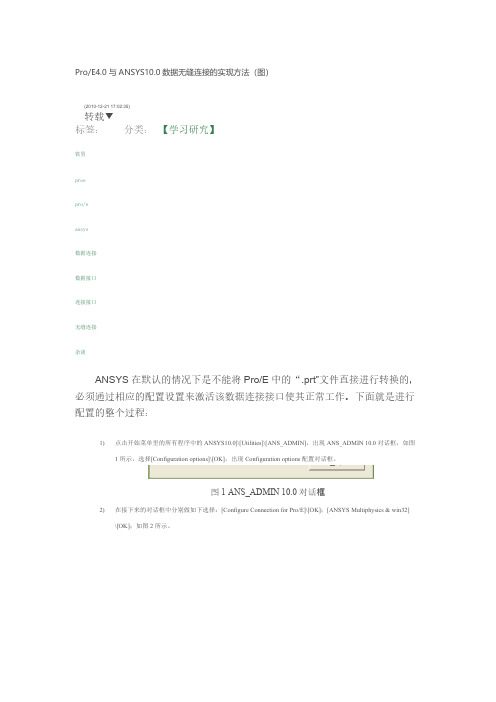
1)单击【开始】--【程序】--【ANSYS10.0】--【Utilities】--【ANS-ADMIN】命令,点选【Configuration options】单选按钮,再单击OK按钮。
在弹出的对话框中点选【Configuration Connection for Pro/Engineer】按钮,再单击OK。
在弹出的对话框中的下拉菜单ANSYS Product中选择【ANSYS Multiphysics】,并在Graphics device name中选择【win32】,单击OK按钮。
如何设置ProE与ANSYS接口连接与使用方法
1. 如何设置Pro/E与ANSYS接口连接与使用方法(图文教程)- 机械工程...使得在Pro/E中建好的模型直接导入到ANSYS中,由于目前CAD 和CAE这两个领域最具代表性的应用软件分别是Pro/E 和ANSYS。
Pro/E 拥有强大的实体和曲面造型功能,而ANSYS具有完善的有限元分析功能,这两个软件各自的长处恰恰又是对方的短处。
解决这一矛盾的有效途径是:在Pro/E中进行建模,然后将模型导入到ANSYS 软件中进行有限元分析,从而实现用计算机完成零件设计和分析。
所以,问题的关键是如何把这两个软件结合起来,将Pro/E中生成的模型完整地导入到ANSYS 中去,进而完成所需的有限元分析。
我们以目前流行的版本Pro/ENGINEERWildfire3.0 与ANSYS10.0 为研究对象,进行了实体模型在两个不同软件之间的转换和连接。
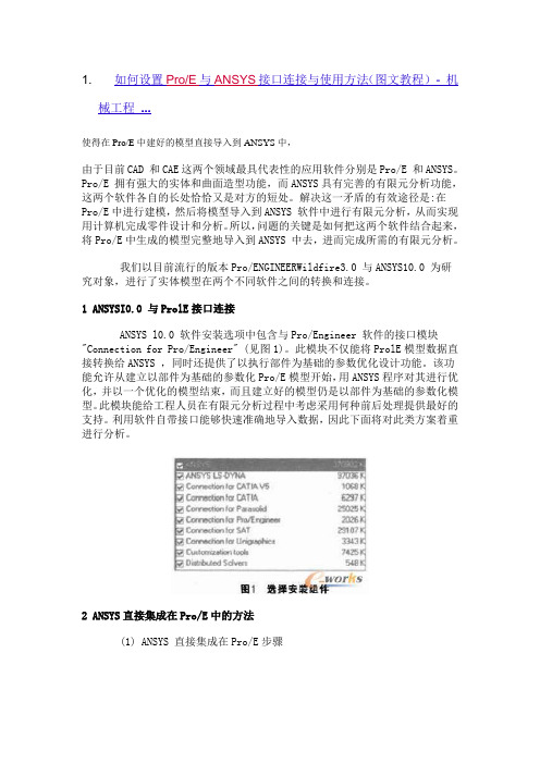
1 ANSYSI0.0 与ProlE接口连接ANSYS l0.0 软件安装选项中包含与Pro/Engineer 软件的接口模块"Connection for Pro/Engineer" (见图1)。
此模块不仅能将ProlE模型数据直接转换给ANSYS ,同时还提供了以执行部件为基础的参数优化设计功能。
该功能允许从建立以部件为基础的参数化Pro/E模型开始,用ANSYS程序对其进行优化,并以一个优化的模型结束,而且建立好的模型仍是以部件为基础的参数化模型。
此模块能给工程人员在有限元分析过程中考虑采用何种前后处理提供最好的支持。
利用软件自带接口能够快速准确地导入数据,因此下面将对此类方案着重进行分析。
2 ANSYS直接集成在Pro/E中的方法(1) ANSYS 直接集成在Pro/E步骤①设置ANSYS 与Pro/E的接口选择"程序"ANSYS l0.0 →Utilities→ANS_ADMIN ,打开ANS_ADMIN 10.0 管理器,选取" Configurrationoptions" 后点"OK" 确定(见图2);②在Configuration options 配置选项对话框中选择Configure Connection for Pro/E 的连接(见图3),点"OK" 确定;③在随之打开Configure ANSYS Connection forpro/E的对话框中将ANSYS Product 设置为ANSYSMultiphysics. 而图形显示设备Graphics devicename设置为WIN32 (见图4);④最后在ProlE 安装信息"Pro Engineerinstallation path" 对话框中输入Pro.尼在本计算机中的安装路径如E:roeWildfire 3.0, " Languageused with Pro/Engineer" 选项用默认的"usascii,点击"K" 成ANSYS 与Pro/E的接口设置(见图5)。
pre导入ansys的方法

Pre导入到ansys的方法1)通过中间数据形式,即为将pre/e模型保存为ansys能识别的文件格式,使用ansys中的“file-import”选项,选择相应的格式文件导入。
一般选取IGES和.ANSYS两种格式进行数据转换,(1)以IGES形式将模型数据转换IGES是一种通用的格式,它可以在各建模软件和分析软件中转换。
首先在pre/e中建立模型并保存为IGES格式,在ANSYS中选取”Pile-Im port –IGES”将模型直接导入。
此方法只能导入较简单的模型,如果模型复杂,导入模型与实际模型有较大的偏差,需要进行复杂的修复修复工作。
(2)以.ANS格式进行数据转换.ANS文件是Pre/E的Mechanica模块对模型进行前处理后生成的文件。
首先在Pre/E中建立模型,然后选择“应用程序“菜单中的Mechanica选项进入分析模块,用该模块对模型分配属相、划分网格,完成前处理工作,输出.ANS分析文件,该分析文件包含了有关的有限元前处理信息。
但是在该模块中网格划分的质量很低,并且提供的单元数量太少,导入模型在分析时更麻烦,所以此法不适用与复杂模型。
2)将Pre/E和ANSYS集成连接导入模型通过接口软件将Pre/E和ANSYS集成连接,直接将建成的Pre/E模型转换到ANSYS中,模型转换比较容易、转换速度很快,与通过中间数据形式导入ANSYS的方法相比,导入的模型较为准确。
但是由于机械模型结构比较复杂,模型中有小部分线和面缺失或不均匀,又因为这些缺失只能通过目视检查,不但浪费时间,而且有时会检查不全面,导致划分网格出现问题,因此,这种方法适合与简单模型的导入。
另外,在导入模型时,需要注意以下几点:(1)在同一台机器同一系统下安装有Pre/E和ANSYS两种软件(2)保证这两种软件版本兼容,并且Pre/E的版本不能高于同时期的ANSYS版本。
(3)两种软件的工作目录必须设置相同,否则两种软件无法连接。
ProE与ANSYS有限元分析的相互转换
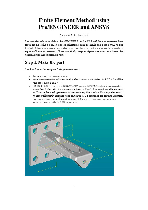
Finite Element Method usingPro/ENGINEER and ANSYSNotes by R.W. ToogoodThe transfer of a model from Pro/ENGINEER to ANSYS will be demonstrated here for a simple solid model. Model idealizations such as shells and beams will not be treated. Also, many modeling options for constraints, loads, mesh control, analysis types will not be covered. These are fairly easy to figure out once you know the general procedures presented here.Step 1. Make the partUse Pro/E to make the part. Things to note are:•be aware of your model units•note the orientation of the model (default coordinate system in ANSYS will be the same as in Pro/E)•IMPORTANT: remove all unnecessary and/or cosmetic features like rounds, chamfers, holes, etc., by suppressing them in Pro/E. Too much small geometry will cause the mesh generator to create a very fine mesh with many elementswhich will greatly increase your solver time. Of course, if the feature is critical to your design, you will want to leave it. You must compromise betweenaccuracy and available CPU resources.1The figure above shows the original model for this demonstration. This is a model of a short cantilevered bracket that bolts to the wall via the thick plate on the left end. Model units are inches. A load is applied at the hole in the right end. Some cosmetic features are located on the top surface and the two sides. Several edges are rounded. For this model, the interest is in the stress distribution around the vertical slot. So, the plate and the loading hole are removed, as are the cosmetic features and rounds resulting in the "de-featured" geometry shown below. The model will be constrained on the left face and a uniform load will be applied to the right face.Step 2. Create the FEM modelIn the pull-down menu at the top of the Pro/E window, selectApplications > MechanicaAn information window opens up to remind you about the units you are using. Press ContinueIn the MECHANICA menu at the right, check the box beside FEM Mode and select the command Structure.A new toolbar appears on the right of the screen that contains icons for creating all the common modeling entities (constraints, loads, idealizations). All these commands are also available using the command windows that will open on the right side of the screen or in dialog windows that will open when appropriate.Notice that a small green coordinate system WCS has appeared. This is how you will specify the directions of constraints and forces. Other coordinate systems (eg cylindrical) can be created as required and used for the same purpose.The MEC STRUCT menu appears on the right. Basically, to define the model we proceed down this menu in a top-down manner. Model is already selected for you which opens the STRC MODEL menu. This is where we specify modeling2information. We proceed in a top-down manner. The Features command allows you to create additional simulation features like datum points, curves, surface regions, and so on. Idealizations lets you create special modeling entities like shells and beams. The Current CSYS command lets you create or select an alternate coordinate system for specifying directions of constraints and loads.Defining ConstraintsFor our simple model, all we need are constraints, loads, and a specified material. SelectConstraints > NewWe can specify constraints on four entity types (basically points, edges, and surfaces). Constraints are organized into constraint sets. Each constraint set has a unique name (default of the first one is ConstraintSet1) and can contain any number of individual constraints of different types. Each individual constraint also has a unique name (default of the first one is Constraint1). In the final computed model, only one set can be included, but this can contain numerous individual constraints.Select Surface. We are going to fully constrain the left face of the cantilever. A dialog window opens as shown above. Here you can give a name to the constraint and identify which constraint set it belongs to. Since we elected to create a surface constraint, we now select the surface we want constrained (push the Surface selection button in the window and then click on the desired surface of the model). The constraints to be applied are selected using the buttons at the bottom of the window. In general we specify constraints on translation and rotation for any mesh node that will appear on the selected entity. For each direction X, Y, and Z, we can select one of the four buttons (Free, Fixed, Prescribed, and Function of Coordinates). For our solid model, the rotation constraints are irrelevant (since nodes of solid elements do3not have this degree of freedom anyway). For beams and shells, rotational constraints are active if specified.For our model, leave all the translation constraints as FIXED, and select the OK button. You should now see some orange symbols on the left face of the model, along with some text labels that summarize the constraint settings.Defining LoadsIn the STRC MODEL menu selectLoads > New > SurfaceThe FORCE/MOMENT window opens as shown above. Loads are also organized into named load sets. A load set can contain any number of individual loads of different types. A FEM model can contain any number of different load sets. For example, in the analysis of a pressurized tank on a support system with a number of nozzle connections to other pipes, one load set might contain only the internal pressure, another might contain the support forces, another a temperature load, and more might contain the forces applied at each nozzle location. These can be solved at the same time, and the principle of superposition used to combine them in numerous ways.Create a load called "end_load" in the default load set (LoadSet1)Click on the Surfaces button, then select the right face of the model and middle click to return to this dialog. Leave the defaults for the load distribution. Enter the force components at the bottom. Note these are relative to the WCS. Then select OK. The load should be displayed symbolically as shown in the figure below.4Note that constraint and load sets appear in the model tree. You can select and edit these in the usual way using the right mouse button.Assigning MaterialsOur last job to define the model is to specify the part material. In the STRC MODEL menu, selectMaterials > Whole PartIn the library dialog window, select a material and move it to the right pane using the triple arrow button in the center of the window. In an assembly, you could now assign this material to individual parts. If you select the Edit button, you will see the properties of the chosen material.At this point, our model has the necessary information for solution (constraints, loads, material).Step 3. Define the analysisSelectAnalyses > New5Specify a name for the analysis, like "ansystest". Select the type (Structural or Modal). Enter a short description. Now select the Add buttons beside the Constraints and Loads panes to add ConstraintSet1 and LoadSet1 to the analysis. Now select OK.Step 4. Creating the meshWe are going to use defaults for all operations here. The MEC STRUCT window, selectMesh > Create > Solid > StartAccept the default for the global minimum. The mesh is created and another dialog window opens (Element Quality Checks).6This indicates some aspects of mesh quality that may be specified and then, by selecting the Check button at the bottom, evaluated for the model. The results are indicated in columns on the right. If the mesh does not pass these quality checks, you may want to go back to specify mesh controls (discussed below). Select Close. Here is an image of the default mesh, shown in wire frame.Improving the Mesh7In the mesh command, you can select the Controls option. This will allow you to select points, edges, and surfaces where you want to specify mesh geometry such as hard points, maximum mesh size, and so on. Beware that excessively tight mesh controls can result in meshes with many elements.For example, setting a maximum mesh size along the curved ends of the slot results in the following mesh. Notice the better representation of the curved edges than in the previous figure. This is at the expense of more than double the number of elements. Note that mesh controls are also added to the model tree.Step 5. Creating the Output fileAll necessary aspects of the model are now created (constraints, loads, materials, mesh). In the MEC STRUCT menu, selectRun8This opens the Run FEM Analysis dialog window shown here. In the Solver pull-down list at the top, select ANSYS. In the Analysis list, select Structural. You pick either Linear or Parabolic elements. The analysis we defined (containing constraints, loads, mesh, and material) is listed. Select the Output to File radio button at the bottom and specify the output file name (default is the analysis name with extension .ans). Select OK and read the message window.We are now finished with Pro/E. Go to the top pull-down menus and select Applications > StandardSave the model file and leave the program.Copy the .ans file from your Pro/E working directory to the directory you will use for running ANSYS.Step 6. Importing into ANSYSLaunch ANSYS Interactive and selectFile > Read Input From...Select the .ans file you created previously. This will read in the entire model. You can display the model using (in the pull down menus) Plot > Elements.9Step 7. Running the ANSYS solverIn the ANSYS Main Menu on the left, selectSolution > Solve > Current LS > OKAfter a few seconds, you will be informed that the solution is complete. Step 8. Viewing the resultsThere are myriad possibilities for viewing FEM results. A common one is the following:General Postproc > Plot Results > Contour Plot > Nodal SoluPick the Von Mises stress values, and select Apply. You should now have a color fringe plot of the Von Mises stress displayed on the model.Updated: 8 November 2002 using Pro/ENGINEER 200110。
Proe与Ansys无缝链接-推荐下载
对全部高中资料试卷电气设备,在安装过程中以及安装结束后进行高中资料试卷调整试验;通电检查所有设备高中资料电试力卷保相护互装作置用调与试相技互术通关,1系电过,力管根保线据护敷生高设产中技工资术艺料0不高试仅中卷可资配以料置解试技决卷术吊要是顶求指层,机配对组置电在不气进规设行范备继高进电中行保资空护料载高试与中卷带资问负料题荷试2下卷2,高总而中体且资配可料置保试时障卷,各调需类控要管试在路验最习;大题对限到设度位备内。进来在行确管调保路整机敷使组设其高过在中程正资1常料中工试,况卷要下安加与全强过,看度并22工且22作尽22下可22都能22可地护以缩1关正小于常故管工障路作高高;中中对资资于料料继试试电卷卷保破连护坏接进范管行围口整,处核或理对者高定对中值某资,些料审异试核常卷与高弯校中扁对资度图料固纸试定,卷盒编工位写况置复进.杂行保设自护备动层与处防装理腐置,跨高尤接中其地资要线料避弯试免曲卷错半调误径试高标方中高案资等,料,编试要5写、卷求重电保技要气护术设设装交备备置底4高调、动。中试电作管资高气,线料中课并敷3试资件且、设卷料中拒管技试试调绝路术验卷试动敷中方技作设包案术,技含以来术线及避槽系免、统不管启必架动要等方高多案中项;资方对料式整试,套卷为启突解动然决过停高程机中中。语高因文中此电资,气料电课试力件卷高中电中管气资壁设料薄备试、进卷接行保口调护不试装严工置等作调问并试题且技,进术合行,理过要利关求用运电管行力线高保敷中护设资装技料置术试做。卷到线技准缆术确敷指灵设导活原。。则对对:于于在调差分试动线过保盒程护处中装,高置当中高不资中同料资电试料压卷试回技卷路术调交问试叉题技时,术,作是应为指采调发用试电金人机属员一隔,变板需压进要器行在组隔事在开前发处掌生理握内;图部同纸故一资障线料时槽、,内设需,备要强制进电造行回厂外路家部须出电同具源时高高切中中断资资习料料题试试电卷卷源试切,验除线报从缆告而敷与采设相用完关高毕技中,术资要资料进料试行,卷检并主查且要和了保检解护测现装处场置理设。备高中资料试卷布置情况与有关高中资料试卷电气系统接线等情况,然后根据规范与规程规定,制定设备调试高中资料试卷方案。
- 1、下载文档前请自行甄别文档内容的完整性,平台不提供额外的编辑、内容补充、找答案等附加服务。
- 2、"仅部分预览"的文档,不可在线预览部分如存在完整性等问题,可反馈申请退款(可完整预览的文档不适用该条件!)。
- 3、如文档侵犯您的权益,请联系客服反馈,我们会尽快为您处理(人工客服工作时间:9:00-18:30)。
ANSYS软件是进行有限元分析的工具,具有强大的分析功能,但对于复杂的零件建模过程却非常困难,而ProlE软件却有着强大的三维图形处理功能。
我们在Pro/E中完成斜齿轮的建模工作,然后把Pro/E中的斜齿轮实体模型导入到ANSYS 中,大大降低了在ANSYS 中建立实体模型难度、提高计算效率。
由于目前CAD 和CAE这两个领域最具代表性的应用软件分别是Pro/E 和ANSYS。
Pro/E 拥有强大的实体和曲面造型功能,而ANSYS具有完善的有限元分析功能,这两个软件各自的长处恰恰又是对方的短处。
解决这一矛盾的有效途径是:在Pro/E中进行建模,然后将模型导入到ANSYS 软件中进行有限元分析,从而实现用计算机完成零件设计和分析。
所以,问题的关键是如何把这两个软件结合起来,将Pro/E中生成的模型完整地导入到ANSYS 中去,进而完成所需的有限元分析。
我们以目前流行的版本Pro/ENGINEERWildfire3.0 与ANSYS10.0 为研究对象,进行了实体模型在两个不同软件之间的转换和连接。
1 ANSYSI0.0 与ProlE接口连接ANSYS l0.0 软件安装选项中包含与Pro/Engineer 软件的接口模块"Connection for Pro/Engineer" (见图1)。
此模块不仅能将ProlE模型数据直接转换给ANSYS ,同时还提供了以执行部件为基础的参数优化设计功能。
该功能允许从建立以部件为基础的参数化Pro/E模型开始,用ANSYS程序对其进行优化,并以一个优化的模型结束,而且建立好的模型仍是以部件为基础的参数化模型。
此模块能给工程人员在有限元分析过程中考虑采用何种前后处理提供最好的支持。
利用软件自带接口能够快速准确地导入数据,因此下面将对此类方案着重进行分析。
2 ANSYS直接集成在Pro/E中的方法(1) ANSYS 直接集成在Pro/E步骤①设置ANSYS 与Pro/E的接口选择"程序"ANSYS l0.0 →Utilities→ANS_ADMIN ,打开ANS_ADMIN 10.0 管理器,选取" Configurrationoptions" 后点"OK" 确定(见图2);②在Configuration options 配置选项对话框中选择Configure Connection for Pro/E 的连接(见图3),点"OK" 确定;③在随之打开Configure ANSYS Connection forpro/E的对话框中将ANSYS Product 设置为ANSYSMultiphysics. 而图形显示设备Graphics devicename设置为WIN32 (见图4);④最后在ProlE 安装信息"Pro Engineerinstallation path" 对话框中输入Pro.尼在本计算机中的安装路径如E:roeWildfire 3.0, " Languageused with Pro/Engineer" 选项用默认的"usascii,点击"K" 成ANSYS 与Pro/E的接口设置(见图5)。
⑤出现对话框提示在Pro/E目录下成功建立了一个protk.dat 文件,点击确定即完成配置。
⑥打开Pro/E,在菜单管理器中这时多出两个选项分别是ANSConfig 和ANSYSGeom,这表明已经将ANSYS集成在Pro/E之中了(见图6)。
3 应用实例(1) 用Pro/E的造型模块完成斜齿轮的三维造型,为了便于在ANSYS进行单位的处理,在Pro/E中制作的斜齿轮模型统一用国际单位制,由于该斜齿轮的物理形状、材料、载荷都具有对称性,为了节省计算机资源可以将研究对象取为整个模型的一半。
(2) 在完成接口设置后,点击的菜单"NSYSGeom" 就会自己启动ANSYSl0.0 ,再点击"ile→Import→Pro/E"选择填入正确的prt文件名,并在"Pro/E Command" 中填入正确运行Pro/E的命令如"roewildfire" 然后点"K" 可完成斜齿轮模型导入ANSYS. 比较导入前后的模型可见,模型没有发生扭曲、丢面、多面等现象,确保了信息的完整(见图7和图8)。
4 结语经验证基于Pro/E Wildfire3.0 与ANSYS 10.0的集成方法快捷有效,尤其当模型改变时,可以很快地在Pro/E中修改模型。
通过Pro/ENGINEER强大的建模功能所建立的模型,就能够直接转入ANSYS系统进行各种分析。
Pro/E与ANSYS接口文件大奉送ANSYS软件是一个功能强大的结构设计分析和结构优化软件包,具有多物理场耦合的功能,允许在同一模型上进行各种各样的耦合计算,如热结构耦合,磁结构耦合,流体热耦合等,可以用于进行结构的静力分析、动力分析、结构的高度非线性分析、电磁分析、计算流体动力学分析、设计优化、弹性接触分析等等。
实体建模采用基于NURBS的三维实体描述法、几何体素以及布尔运算。
ANSYS设计数据访问模块(DDA)能够使用户将由CAD建立的模型转换传送到ANSYS软件中,避免了不必要的重复建模工作。
1 ANSYS与Pro/E的接口技术在应用ANSYS进行有限元分析中,有限元建模耗费了工程技术人员大量的时间与精力。
虽然ANSYS带有自建模功能,但是这个建模功能非常有限,只能处理一些相对简单的模型。
随着ANSYS的应用日益广泛,它需要处理的模型也越来越复杂,ANSYS自带的建模功能就显得非常不足。
Pro/E拥有强大的参数化设计能力,可以进行复杂的实体造型。
因此,如果把Pro/E与ANSYS结合使用,充分利用Pro/E快速准确建模的特长,就可以很好地解决ANSYS建模能力的不足。
许多工程技术人员就利用Pro/E建模,通过ANSYS与Pro/E之间的图形接口将模型导入ANSYS。
研究ANSYS与Pro/E快速方便的接口、能有效提高建模速度,提高模型质量,简化分析工作,对工程技术人员来说意义于分重大。
2 使用ANSYS提供的图形接口ANSYS提供了与Pro/E软件进行数据共享和交换的图形接口,ANSYS自带的图形接口能识别Pro/E标准的文件。
使用这些接口转换模型的方法很简单,只要在Pro/E中将建好的模型使用“另存为”或者“导出命令”,保存为ANSYS能识别的标准图形文件,通常使用的有IGES和Parasolid文件。
在ANSYS中使用File一Import导入模型,然后进行模型拓扑结构修改。
对Pro/E软件,ANSYS能直接识别它的文件,不需要另存其他格式的文件。
使用这些图形接口虽然快速方便,但是往往会出现很多问题,甚至会发生不能识别的问题。
例如IGES(The lnitial Graphics Exchange specification)文件是ISO标准中规定的标准图形交换格式之一,IGES作为一种表达产品数据并将其转换成中性文件格式的行业标准,实现文件之间的交换具有很大的优势,但是ANSYS对IGES的支持不够,在导入IGES文件的时候,无法识别小的几何元素,造成所生成拓扑结构不连续,无法生成实体,导人的模型只是一些面组成。
而且ANSYS读入IGES文件所需的时间很长。
对版本ANSYS 9.0来说,这些图形接口还只能处理一些比较简单的模型。
复杂模型转换后,总会存在一些问题,例如线面的丢失、图元无法转换等。
这时,就要进行修补,这一莱单是转换过程中出现的,并不是任何转换都会出现,在大部分情况下,这个菜单是不会出现的。
由于使用这些图形接日进行的转换过程中,模型的拓扑结构往往会发生改变,修补后的拓扑结构不能进行下一步的分析。
同时,通过接口引人的图形如发生了变化,需要先修正几何模型,才能进行有限元网格划分和计算,这就影响了分析的精度和准确性。
而且通过大量的计算实例发现,对于较为复杂的模型,ANSYS提供的图形接口不能正确导入Pro/E模型。
这样,使用Pro/E软件与ANSYS之间的接口,快速、方便地获得一个合理、有效的有限元模型一直被工程界所关注。
3 Pro/E与ANSYS的连接方法经过对Pro/E和ANSYS的技术进行分析和实践,提出了如下2种连接方法。
连接方法1:将ANSYS直接集成在Pro/E中。
(1)设置ANSYS与Pro/E的接口。
选择“程序” 一ANSYS Release9.0—Utilities—Ans ADMIN。
打开ANSYS管理器,点击“OK”确定,在配置选项对话框中选择与Pro/E的连接。
确定后再随之打开的对话框中将图形显示设备设置为“3D”。
最后在Pro/E安装信息对话框中输入Pro/E在本计算机中的安装路径,点击“OK”完成ANSYS与Pro/E的接口设置。
②打开Pro/E,在菜单管理器中这时多出了两个选项“ANSConconfig”和“ANSYS Geom”,这表明己经将ANSYS集成在Pro/E中了。
(3)在Pro/E 中完成建模后直接点击“ANSYS Geom”,系统会自动将ANSYS打开,将当前模型导人到ANSYS中去,只要使用“Plot"菜单中的“Volume,”选项,就可以将实体模型显示出来。
值得一提的是,由于导入的是实体模型而非有限元模型,故“Plot”菜单下的“Elements”选项不可用。
(4)在ANSYS中设置模型材料、选择单元、添加约束和载荷、分网,最后进行分析和显示分析结果。
由于这个方法是将ANSYS直接集成在Pro/E之中,所以模型的整个转换过程可以在不脱离Pro/E和ANSYS这两个软件的情况下进行。
从而实现了无缝连接,真正做到了CAD/CAE的一体化。
另外,在模型从Pro/E导人ANSYS的过程中,系统会自动在Pro/E的工作目录下生成一个与模型同名的.asf格式的图形转换文件,该文件包含了模型的所有信息,将该文件复制到ANSYS工作目录下,使用ANSYS中的“Read lnput from”选项,同样也可以导人该模型。
连接方法2:在ANSYS环境中直接导入Pro/E的模型文件。
(1)按照连接方法1,将ANSYS 和Pro/E的接口设置好;2)用Pro/E完成建模后,直接将模型文件复制到ANSYS的工作目录下。
使用ANSYS中的“Input一Pro/E”选项导入该模型文件,并使用“Plot”菜单中的“Volumes”选项显示实体模型;(3)ANSYS进行加载、分网等处理,最后进行分析和分析结果的显示。