柯泰报警器说明书kt—g7
柯泰HT9110G报警器说明书
柯泰HT9110G报警器说明书柯泰HT9110G报警器可谓是当今社会科技快速发展的产物,所谓柯泰的意思就是利用网络讯号可以连通主人手机电话,实现远程防盗功能。
柯泰防盗报警器可谓是智能化多功能的新一代安防产品了,一般有条件的家庭都会安装有防盗报警器了,安装有柯泰防盗报警器。
一、产品性能:1、产品特点:自动安装:系统各部分不需布线,柯泰连接安装方便。
无需设置:通电即可使用。
操作方便:只需按遥控器按键,即可实现各种功能。
功能齐备:配套合理,价格低廉。
2、产品功能:红外人体探测器:在警戒空间,探测非法活动人体并报警。
门窗防撬报警器:通过门磁探测非法打开门、窗并报警。
紧急报警:发生意外情况,按遥控器上的报警键,主机发出报警信号。
二、系统简介:1、系统包括:主机、红外人体探测器、门磁探测器,遥控器,高音警号,12V电源变换器。
2、主机是系统的控制中心,各种探测器和遥控器发出的信号都必须通过主机来接收、识别才能报警。
安装时先把主机挂在墙上或者放在台面上,然后把电源变换器的输出插头插入主机背后的电源插孔中,变换器插入220V插座上即可。
3、遥控器用来对主机进行待机、警戒、紧急呼救等状态的设置,需随身携带。
4、主机报警时,高音警号能发出120dB的强声威吓入侵者。
安装时可用自带的不干胶直接粘贴,也可用螺钉固定在合适的位置,把插头插入主机背后的“警号”插座。
5、门磁传感器主要用来探测门或窗是否被非法撬开,安装时用不干胶直接固定在门或者窗上,门磁探测器分为两部分:一个是门磁主体,一个是磁铁。
安装时把门或窗关闭,保证门磁主体和磁铁上下对齐,且两者相距不大于1CM即可。
Ck报警器使用与编程

Ck报警器使用与编程布防(即开启报警主机)键入密码#1 确保绿色指示灯READY亮。
如果绿色指示灯READY熄灭,某红色区域(ZONE)指示灯亮,表明该保护区域内被入侵(如门窗忘记关闭,有人在探头监视的区域内活动等)。
2 键入数学密码及#如密码为1234,由输入1234#,#表示输入。
每个键入间间隔时间不得超过5秒,否则键盘会“嘀嘀嘀嘀嘀”连续5声表示输入无效。
须重新输入。
3 红色指示灯ARM亮。
同时键盘“嘀—嘀—嘀”提示用户退出。
(236键盘缺省为无提示音)。
退出延时时间快结束时,“嘀-嘀-嘀”越发紧促。
二、撤防(即关闭报警主机)键入密码#从正常入口进入时,键盘会“嘀-嘀-嘀”提示用户输入密码。
如果在特定的时间内还不输入正确的密码,报警主机则以为是非法入侵,警号大作,并向接警中心发送警情。
三、人为误报(如不慎触发紧急按钮)键入密码#请不要紧张,输入密码可关闭警号。
报警主机自动向报警中心发送用户取消报告。
中心人员根据取消报告即可知道为误报。
四、每次报警后,消除报警记忆键入*1#报警后,该防区的指示灯一直处以闪烁状态。
键入*1#可予消除。
五、旁路某一防区密码BYPASS防区号#如某一防区发生故障或该防区一直有人在活动,可以在布防之前把该防区旁路,而使其它防区处以警戒状态。
BYPASS为最右下角的按键。
注意:被旁路的防区不受保护。
六、解除旁路某一防区密码BYPASS防区号#七、修改密码若您想要改密码,并使原密码作废,改法如下:236/2316主机:原密码*0# 1# 新密码# 新密码# *#,新密码为任意4位数。
238主机:原密码*0# 新密码# 新密码#*#。
新密码必须是开头为1的2~5位数。
八、指示灯的含义及故障判别POWER:电源灯,表示交流电供电正常ARM:布防灯,表示系统处于布防状态READY:表示防区都处于正常状态,可以布防SERVICE:故障灯,具体含义见下表。
故障灯亮时不影响主机正常使用。
报警器使用说明书
一、概述:品牌大眼睛型号HP-99GSM类型防盗报警电话工作电压12(V)无线接收频率315(MHz)报警喇叭声强120(dB)录音留言时长6(S)储存电话号二、详细说明:品牌大眼睛型号HP-99GSM类型防盗报警电话工作电压12(V)无线接收频率315(MHz)报警喇叭声强120(dB)录音留言时长6(S)电话号码位长11(位)密码设置功能有系统安装系统简介本报警器由报警主机和各种无线连接的配件组成。
当有人非法进入设防区域时,主机就会发出警报声,并且拨打主人的电话,主人收到通知后可立即赶回家或通知附近的亲朋好友处理,也可以通过电话监听现场的声音,进行远程操作。
报警器安装把电话线外线插头插入主机的LINE2孔,用报警器附带的电话线将主机的LINE1孔与电话机相连,然后接上电源和警号,此时主机会发出“B”的一声,电源指示灯常亮,表示主机已开始工作。
门磁安装将随机配备的双面胶把磁条贴在门上,门磁发射盒贴在门框上,安装时注意将磁条靠近发射盒上有指示灯一侧,两者对齐,间距越小越好。
xx探测器的安装红外探测器的原理是感应人体发出的红外线信号,它能感应到人体的移动,探测距离通常为5-12米,红外探头应装在离地2.2米左右的位置,对准要探测的区域。
红外只能安装在室内,不要对着太阳光,不要对着窗户及温度容易改变的地方。
红外安装的位置会影响到探测距离及探测的准确性。
GSMxx安装抽出主机背后的SIM卡盖,用手指压住SIM卡座向后推动,翻开卡座盖板,将SIM卡按豁口位置插入盖板,保持SIM卡缺角与板上缺角方向一致,压下盖板向前推动扣住SIM卡即可。
功能设置所有设置都需要在撤防下进行,所有正确的操作均是长响一声,错误的操作都是两声短响储存电话号码6(个)报警项目多功能调节报警时警笛音量# 0(0~99)#报警时调节警笛音量大小,0到99之间选择,0是无声,99是最大声。
设置普通报警电话号码#(1~5)?...?#设置1~5组电话号码,“1~5”为电话号码的序号;此处“?...?”代表电话号码。
柯泰报警器红外感应设置说明书[001]
![柯泰报警器红外感应设置说明书[001]](https://img.taocdn.com/s3/m/6fe81b8a970590c69ec3d5bbfd0a79563c1ed4ac.png)
柯泰报警器红外感应设置说明书柯泰报警器红外感应设置说明书感谢您购买柯泰报警器红外感应设备。
本说明书将为您介绍如何正确设置红外感应器,并提供一些建议以确保设备的最佳工作效果。
请您仔细阅读以下内容,并按照说明进行操作。
第一步:选择安装位置在开始设置之前,请确定所安装的位置。
红外感应器是一种非常灵敏的设备,因此请确保所选位置能够覆盖您想要监控的范围,并尽量避免有干扰的区域,例如直射阳光、空调出风口等。
同时,考虑到避免误报警情况的发生,请将红外感应器安装在高于人体行走范围的位置。
第二步:设置感应范围柯泰报警器红外感应器具有可调节的感应范围功能。
您可以根据实际需求,自由选择监测的范围。
在设置感应范围时,建议将红外感应器平行于所需监控的区域,以确保最佳的监测效果。
如果需要监控更大的范围,您可以适当调整感应器的角度,或考虑安装多个感应器以覆盖更广的区域。
第三步:调节感应灵敏度为了避免无效报警和漏报警情况的发生,柯泰报警器红外感应器提供了灵敏度的调节功能。
一般来说,我们建议在正常情况下将灵敏度设置为中等水平。
当有人或其他动物进入监测范围时,如果感应器未触发,请适当增大感应灵敏度;如果频繁误报警,请适当减小感应灵敏度。
请注意,过高的感应灵敏度可能会导致虚警,而过低的灵敏度可能会导致漏报。
第四步:测试感应器工作状态设置完成后,请进行感应器的测试以确保其正常运行。
您可以让有人或动物进入监测区域,观察感应器的反应。
如果感应器正常工作,它将及时触发报警器,发出相应的声音或光信号。
请务必确认报警器的工作状态,以确保在必要时可以及时报警,保护您的家庭安全。
第五步:维护和保养为了保持红外感应器的良好工作状态,请定期清洁设备表面,避免积尘和其他杂物对其造成影响。
同时,注意保持感应器周围环境的整洁,避免堆放杂物或遮挡感应器。
希望上述内容能为您提供一些建议和指导,以帮助您正确设置柯泰报警器红外感应器。
如有任何疑问或需要更多帮助,请随时联系我们的客户服务团队。
柯泰kt-g7报警器说明书
柯泰kt-g7报警器说明书柯泰KT-G7报警器说明书一、产品概述柯泰KT-G7报警器是一款高性能的家庭安防设备,具有报警、监控、防护等多种功能。
通过先进的技术和可靠的性能,为用户提供安全可靠的家庭保护。
二、产品特点1. 多种报警方式:支持声光报警、手机短信报警等多种报警方式,确保报警信息的及时传达和用户的迅速响应。
2. 多通道监控:支持多通道视频监控,可连接多个监控摄像头,全方位实时监控家庭安全。
3. 远程控制:用户可通过手机APP远程控制报警器,随时随地查看家庭动态和报警信息。
4. 高灵敏度传感器:采用先进的传感器技术,能够准确感知周围环境变化,并进行及时的报警。
5. 防拆报警功能:具备防拆报警功能,一旦遭到破坏,将立即报警。
三、产品安装1. 室内安装:将报警器固定在室内墙壁上,保证报警器稳定可靠;2. 电源接入:将电源适配器接入报警器,确保正常供电;3. 监控摄像头连接:将监控摄像头连接到报警器上,确保摄像头能够正常工作;4. 连接网络:将报警器连接到家庭网络,确保远程控制能够实现。
四、报警器设置1. 报警方式设置:通过报警器面板或手机APP进行报警方式的设置;2. 传感器灵敏度调节:根据实际需求,调节传感器的灵敏度;3. 多通道监控配置:通过手机APP进行监控摄像头的添加和配置;4. 远程控制设置:通过手机APP进行远程控制功能的设置。
五、注意事项1. 请将报警器安装在儿童无法触及的位置,防止误碰和损坏;2. 请确保电源稳定,并避免电源适配器的损坏;3. 定期检查各部件的运行状况,确保报警器的正常工作;4. 请妥善保管报警器的相关密码和账号信息,避免泄露。
六、售后服务如需了解更多产品信息或购买配件,请联系本公司售后服务部门。
感谢您选择柯泰KT-G7报警器,我们将竭诚为您提供满意的服务!。
柯泰g7报警设置说明书
柯泰g7报警设置说明书柯泰G7报警设置说明书注意事项:1. 本说明书适用于柯泰G7报警设置操作。
2. 请仔细阅读本说明书,按照步骤正确进行报警设置。
3. 若有疑问或需要进一步了解,请咨询柯泰客服。
一、开关机设置1. 打开柯泰G7报警器,按下电源键进行开机。
2. 关机时,长按电源键进行关机。
二、报警设置1. 选择报警模式:a. 进入主菜单,找到“报警设置”选项,点击进入。
b. 在报警设置界面中,选择所需的报警模式,如声音报警、震动报警等。
2. 设置报警状态:a. 在报警设置界面选择“报警状态”。
b. 在“报警状态”选项中,设置所需的报警状态,如开启、关闭。
3. 设置报警参数:a. 在报警设置界面选择“报警参数”。
b. 在“报警参数”选项中,根据需要设置相关参数,如报警音量、报警时间等。
4. 设置报警联系人:a. 在报警设置界面选择“报警联系人”。
b. 在“报警联系人”选项中,编辑报警联系人的姓名和手机号码。
5. 设置报警信息:a. 在报警设置界面选择“报警信息”。
b. 在“报警信息”选项中,编辑需要发送的报警信息内容。
6. 报警测试:a. 在报警设置界面选择“报警测试”。
b. 在“报警测试”选项中,点击“开始测试”进行报警功能测试。
三、保存设置1. 在报警设置界面,选择“保存设置”。
2. 确认保存设置后,退出报警设置并返回主页面。
注意:1. 请确保按照正确的操作步骤进行报警设置,避免不必要的问题。
2. 如有需要,可以随时修改报警设置,重新进入相应菜单进行操作。
以上就是柯泰G7报警设置的操作说明。
如有其他疑问或需要进一步帮助,请联系柯泰客服。
G7 设备用户指南说明书

G7Getting Started:G7’s Hardware and Gas DetectionCharging lightCartridge (Standard, Single-gas(G7c only)OK buttonUp button LCD screen Speaker Latch pull*Latch push**Real-time customers only, if you are interested in these features, please contact your sales representative.Down button Connectivity lightYOUR G7OKCHARGINGPOWERING ONUSING G7’S MENUTo charge the battery, insert the micro USB cable into the removable charging clip, then slide the clip onto the charging port at the bottom of your G7.A solid red light at the bottom of the device confirms your G7 is charging. The LCD screen will show charging and battery levels.Blackline recommends that you fully charge your device after every shift.Micro USB cableRemovable charging clipChargingport G7’s menu is where you can access different items, such as gas options, messages, settings and advanced info.To use G7’s menu:1.Press OK once to wake up G7’s screen2.Press OK again to enter the main menue the up and down arrow keys to navigate to the selection you would like4.Press OK to select a menu item5.Repeat as necessaryOK buttonPress to open the main menu andconfirm menu selections.Up and down arrow buttons Press to navigate the menu.Visit to download the technical user manual with descriptions of how to use and configure your device features and specifications.CUSTOMER CAREFor technical support, please contact our Customer Care team.North America (24 hours)Toll Free: 1-877-869-7212 | ***************************United Kingdom (8am-5pm GMT)+44 1787 222684 | *****************************International (24 hours)+1-403-451-0327 | ***************************LEARN MORE0076/R10/2018-08-13What does the green light indicate?G7’s green connectivity light has two states:A flashing connectivity light indicates that your G7 is storing data. It is not currently connected to the network and will send data when the light is solid.A solid connectivity light indicates that G7 is actively transmitting data and is connected to the Blackline Safety Network.To turn on G7, press and hold the power button for two seconds. G7 will beep and vibrate when it turns on.NOTE: If you are using real-time features,your safety is only monitored when the connectivity light is solid.GAS DETECTION BUMP TEST AND CALIBRATIONGAS ALERTS & ALARMSWhat is a calibration?Gas sensors periodically need to be calibrated by applying a known concentration of gas for a set amount of time. This ensures the gas sensor can accurately detect gas levels. The calibration schedule depends on your company’s safety policy. Blackline recommends not exceeding 180 days without a calibration.What is a bump test?It is safe practice to regularly test gas sensors by applying the target gas. G7’s bump test also tests the operation of light, sound and vibration indicators. The bump test schedule depends on your company’s safety policy.Zeroing sensorsIf G7 is not reading zero (or baseline) and you know you are in an atmosphere with no gas, your gas sensor readings may have shifted. If this happens you can zero your sensors to reset the baseline. Zeroing should only be completed if you are certain you are in a safe environment.G7 devices with a Single or Multi-gas cartridge are capable of detecting gases in your environment.G7 monitors your environment and will notify you of gas exposure with a yellow warning or red alert.All gas settings are customizable withinBlackline Live. Speak to your safety supervisor to learn about how your G7 gas features are configured.M ul t i -g a s G 7Si n g l e -g a s G 7Low warning alarm for gasIf a sensor detects a low concentration gas level.UL (under limit)If a sensor’s baseline shifts and is unable to obtain an accurate gas reading.Sensor errorIf a sensor stops working for any reason.Calibration and bump testIf a sensor is due for a calibration or bump test.High alert for gasIf a sensor detects gas levels above the maximum gas concentration.STEL (short term exposure limit) If a sensor detects you have reached the short-term exposure limit configured.TWA (time weighted average)If you have reached the average gas amount of repeated gas exposure in an eight-hour period.OL (over limit)If excessive amounts of gas are detected and sensors can’t provide an accurate gas reading.YELLOW WARNING ALARM RED ALERTTubingHow to manually bump or calibrate single, multi-gas and pump cartridges:1.Attach calibration cap to one end of the tubing 2.Attach the other end of the tubing to a fixed flow regulator on your calibration gas cylinder 3.Attach the calibration cap to the cartridge 4.Press OK to access the main menu ing the up and down arrows,navigate to gas options 6.Select OK to enter the gas options menu e the OK button to select bump test or calibration 8.Follow the instructions on G7’s screen to complete the calibration or bump testG7 DockBump tests and calibrations can also be done using G7 Dock, where the process is automated for you.To bump test or calibrate with G7 Dock:1.Place G7 in Dock at a 30 degree angle 2.Lower the top of G7 into G7 Dock,pressing until you hear a click 3.Close Dock’s lid4.Select bump test or calibration from the Dock menu on G75.Allow G7 Dock to run and remove G7when the screen prompts youIf you do not have G7 Dock and are interested in ordering, please contact your distributor, sales representative, or our Customer Care team.。
ATS自动转换器控制器7英寸远程报警器控制器说明书
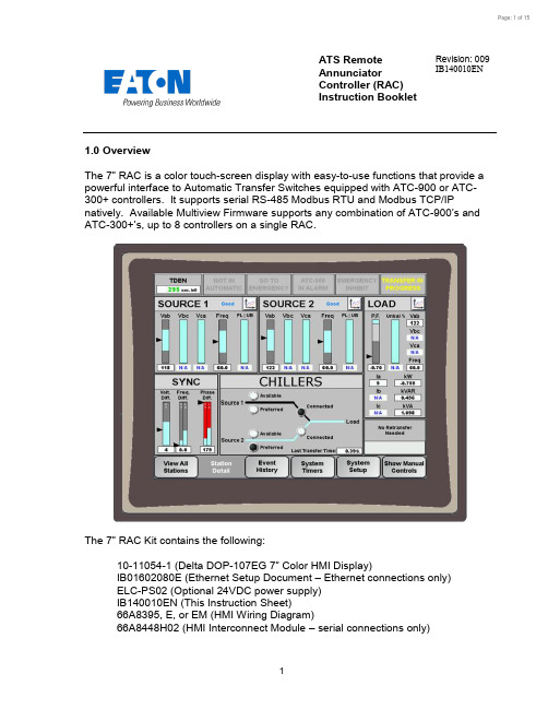
ATS Remote Annunciator Controller (RAC) Instruction BookletRevision: 009 IB140010EN1.0 OverviewThe 7” RAC is a color touch-screen display with easy-to-use functions that provide a powerful interface to Automatic Transfer Switches equipped with ATC-900 or ATC-300+ controllers. It supports serial RS-485 Modbus RTU and Modbus TCP/IPnatively. Available Multiview Firmware supports any combination of ATC-900’s and ATC-300+’s , up to 8 controllers on a single RAC.The 7” RAC Kit contains the following: 10-11054-1 (Delta DOP-107EG 7” Color HMI Display ) IB01602080E (Ethernet Setup Document – Ethernet connections only) ELC-PS02 (Optional 24VDC power supply) IB140010EN (This Instruction Sheet) 66A8395, E, or EM (HMI Wiring Diagram) 66A8448H02 (HMI Interconnect Module –serial connections only)2.0 FeaturesThere are three types of features incorporated into the RAC: Status, Control, and Setpoint Editing.Status Indicators∙S1 / S2 Available∙S1 / S2 Preferred (ATC-900 only)∙S1 / S2 Connected∙S1 / S2 Status∙Emergency Inhibit∙Lockout / Monitor Mode∙Go to Emergency Active∙Engine Test Active∙Transfer in Progress∙Source 1 Voltage Metering∙Source 2 Voltage Metering∙Load Voltage Metering (ATC-900 only)∙Load Current Metering (ATC-900 with DCT module only)∙Waiting for Manual Retransfer∙History of Events∙Active Timers∙Last Transfer Time (ATC-900 only)Controls∙Go to Emergency / Cancel Go to Emergency∙Start / Stop Engine Test∙Alarm Silence∙Remote Alarm Reset∙Bypass Timers∙Manual Retransfer3.0 Setup and WiringThe RAC requires a 24VDC voltage source with a minimum current of 360 mA. There is a removable terminal block connector on the back of the unit for incoming power termination.The RAC supports Modbus RTU (serial RS-485) and Modbus TCP/IP (Ethernet). However, since ATS controllers only support Modbus RTU, an RS-485 serial-to-Ethernet gateway must be used for Modbus TCP/IP. Eaton recommends using the ELC-CAENET module or a Power Xpert Gateway (PXG-900).Drawing 66A8395 shows the wiring of the unit over serial Modbus. Consult drawing 66A8395E (or EM) when using Ethernet gateways. All RS-485 serial cable must have three insulated conductors (D0, D1, COM) and one ground (drain) connected to theshielding of the cable. The Eaton recommended cable is Belden 3106A. Ethernet cable may be any CAT5/6 certified cable.Note: multiple Modbus Ethernet gateways may be used to further expand thecommunication flexibility of the system. Drawing 66A8395EM should be referenced for wiring of multiple gateways. This requires custom firmware per installation site.DOP-107EG Rear ViewELC-CAENET Ethernet Gateway PXG-900 Ethernet Gateway3.1 ATS Controller SetupEvery ATS controller connected to the RAC needs to be set as follows: Modbus Configuration (ATC-900): 9600, 1-stop, NoneBaud Rate (ATC-300+): 9600Address: 01, 02, 03, 04, 05, 06, 07 or 08 (each controller connected to a single RAC must be a unique address)Termination SW1: Normally set to OFF. However, for long communication runs or when experiencing communication timeouts, a 120 Ohm resistor may beinstalled on one end of the communication daisy-chain (see drawing 66A8395 for proper resistor location). If this is done, SW1 must be set to ON only on the last controller in the communication daisy-chain. All other controllers must be set to OFF.3.2 RAC SetupThe firmware comes preloaded onto the unit according to your switch configuration when ordered through your Eaton ATS distributor and should require no user firmware uploading. If your firmware is corrupt or the wrong version was uploaded, please contact ATS Tech Support for assistance.Your RAC is factory set with communications disabled for all controllers and must be enabled during startup. To enable communications, press on any disabled controller from the Overview screen (or the Station Detail screen for Singleview Firmware). Enter your level 2 password (default of AC45). A list of available controller com links will appear. To enable communications to a controller, press the red “Disabled” button under the Coms column; it will change green and display “Enabled”. To disable communications to a controller, press the green “Enabled” button; it will chan ge back red and display “Disabled”. More detail is available in Section 4.5.4.0 RAC ScreensThe RAC has a total of 6 screen types. The following is a summary of the available screens and their function:∙Overview– In a multi-controller system, this shows the status of all controllers at once. This screen will not be shown if you only have a single controllerenabled in the System Setup screen.∙Station Detail– Shows a more detailed view of a single station and gives limited control functionality.∙Trend Data (S1/S2/Load) – Shows trend data (voltage, frequency, unbalance, and load current) for each of the sources and load.∙Alarms and Events– Shows the user a time and date-stamped list of certain events and alarms.∙System Setup– Allows naming, enabling/disabling coms, and setpoint editing of each controller along with password and HMI setup.∙Controller Setpoints – Allows viewing and editing of every available setpoint on the ATS controllers.4.1 Overview ScreenThe Overview screen (Multiview firmware only) shows the status of up to 8 ATS controllers. In the example above, Station 1, an ATC-900 transfer switch named ATS1, has S1 connected, S2 preferred, and no bus energized. Station 2, an ATC-300+ transfer switch named DEMO ROOM, has S1 available and connected. Station 3 has timed out and is trying to reconnect automatically. Station 4, an ATC-900 named CHILLERS, is connected to S2 (non-preferred source) due to a S1 power failure. Stations 5 through 8 are disabled per the user.To view more details and controls for any communicating transfer switch, press anywhere inside the desired station window. This will take you to the Station Detail screen (section 4.2) for that transfer switch.If any controller has an Alarm condition, anaudible alarm will sound from the RAC. To viewthe alarm, press on the station window of thealarmed controller. Once you are on the StationDetail screen, an alarm popup window shouldbe displayed. To silence the alarm, press“Silence Alarm s” button. To perform a remotealarm reset, press the “Remote Alarm Reset”button (only available on ATC-900 controllers).To close the a larm popup, press “Close”.To view the alarm popup window again at any time, press the “ATC -xxx IN ALARM” indicator on the Station Detail screen.4.2 Station Detail ScreenThe Station Detail shows a more detailed view of a single controller. Note: ATC-300+ controllers have no Load monitoring. The top area contains status indicators. Status indicators change from gray to ayellow or red color when active.Below the status indicators are the Source 1, Source 2, and Load detail windows. These windows include graphical and numerical represen-tations of voltage, frequency, and phase loss/unbalance as well as status indication and a trend screen button (Section 4.4). If your controller has a DCT Module add-on, you will see additional Load metering including kilowatts,kVAR, kVA, power-factor, and three-phase current.The voltage, frequency, phase-loss, and unbalance indicators have been designed to show aquick graphical representation of how ‘healthy’ the source is. The top grey area indicates the Over-voltage or frequency dropoutrange. The bottom grey area indicates the Under-voltage or frequency dropout range. The middle light-blue area indicatesthe “good” range. These areas resize dynamically depending on how the dropouts are set in the controller setpoints. If the voltage or frequency reaches the upper or lower ranges, they will turn from grey to red, indicating a problem. Note that the numerical value will change to “N/A” if the va lue is ever invalid (e.g. Vbc, Vca, and Unbalance in a single-phase system.)Below the Source 1, Source 2, and Load status windows is the Source Sync window. On three-phase systems, this window will display how far apart the two power sources are from each other. The difference is given in Volts, Frequency, and Phase. When closed transition or in-phase is enabled, the allowable range will be shown on the bar graph. If the difference is higher than the allowable range, it will turn from grey to red, indicating that it is not okay to do an in-phase or closed transition at that time.Note that there are different indicators for closed (CT) and in-phase (IP) transitions for Frequency and Phase Difference. ATC-300+ only supports in-phase transitions.To the left of the Source Sync window is the Mimic Bus window. This window acts identically to the mimic bus onthe System Overview screen.The upper banner displays thename of the selected controller. The bus area shows which source is available, preferred,and connected. Active lights are white, while inactive lights are black. The currently energizedbus is depicted by a light-bluecolored line.To the right of the Mimic Bus area is the Manual Retransfer window. This area indicates whether manual retransfer isenabled or disabled, as well as alertingthe user if the transfer switch controller is waiting for a manual retransfer signal. The manual retransfer can be initiated remotely by pressing the button labeled “Press to Retransfer” when it appears on the RAC (password protected, level 1).The bottom area of the screen shows navigation and control buttons. The “View all Stations” button navigates to the Overview Screen (Section 4.1). Note: this button is not available if only a single station is enabled. The “Event History” button navigates to the Alarm/Events Summary screen (Section 4.3). The “System Setup” button navigates to the System Setup screen (Section 4.4).Show/Hide Manual Controls: This button expands a small window with 3 control buttons: Go to Emergency, Bypass Timers, and Start Engine Test. All control is password protected level 1. To hide the manual controls, press the “Hide Manual Controls” button.Start Engine Test/Cancel Engine Test: To initiate an engine test remotely from the RAC, press the Start Engine Test button and enter your level 1 password. The controller will close its generator start contacts. Once the generator has reached nominal voltage, the test will run until the Engine Test Run Time expires. If your controller is programmed for a Load Transfer test, then it will also transfer your load to the generator during the test. To abort the test early, push the Cancel Engine Test button on the RAC.Go to Emergency/Cancel Go to Emergency: This button sends the controller a remote Go to Emergency command (password protected, level 1). Once initiated, the controller will transfer to your non-preferred (emergency) source. To go back to your preferred (normal) source, push the Cancel Go to Emergency button.Bypass Timers: Allows the user to skip a currently active timer. While a valid timer is counting down, simply press the button, enter the level 1 password, and it will be bypassed. This button works for the following timers:4.3 Alarm and Events ScreenControllerEventsControllerAlarmsThe Alarm and Events screen displays time/date-stamped alarms (in red) and events (in black) for all connected controllers. This information is s tored in the HMI’s memory, and will not be erased if the unit is powered down. Therefore, a “Reset History” pushbutton is provided to clear all historical events and alarms if needed. A list of all available messages is shown below:4.4 Trend ScreensTrendLabelOverfreq.RangeUnderfreq.RangeNavigationSlidersCurrentData PenThe Trend screens show a graphical representation of Voltage, Frequency, Unbalance, and Amperage (Load trend only). The HMI takes data samples every 1 second for each controller it communicates to. The internal storage of the HMI can store up to 8.6 hours of historical data. The HMI can be configured from the factory to export and store additional data on an external USB drive or SD card. Additionally, data saved to external devices can be viewed on any PC program that supports CSV files.If applicable, the trend windows also display the Under/Over-Frequency, Voltage, and Unbalance limits as set in the ATC-900. These are depicted by the red horizontal lines on each trend window.To view trend data on the HMI, simply press the Trend button of the voltage source you wish to view (Source 1, Source 2, or Load). Once on the trend screen, you can go back and forth through time by using the scroll bar and arrows on the bottom of each trend window. The most recent data is on the right side of the trend window, while the oldest data is on the left side. To see a data point value at a specific point in time, press on the screen at the desired point and the HMI will draw a vertical line there and display the data value.4.5 System Setup ScreenStation Name: The RAC allows the user to name each ATS controller (up to 8 controllers per RAC with Multiview Firmware). Simply press the Edit button next to the controller you wish to name and type in your desired name using the on-screen keyboard.Coms: The user can also enable/disable any communication link between the RAC and controller by pressing on the Enabled/Disabled button next to the corresponding controller. When enabled, the display will show a green “Enabled” button; when disabled, the display will show a red “Disabled” button. To toggle the communication state, simply press the button and the state will toggle.Coms Status: The RAC will display the current status for all 8 stations. Possible coms statuses are:∙Off – Coms are Disabled∙Trying to Connect – Coms are enabled but have not been established yet.∙Timed Out – Coms have been established but are now not responding.∙Good – Coms have been established and no issues are detected.Type/FW Ver.: When Coms are enabled for the first time, the RAC will automatically poll the controller to see what type it is (ATC-300+ or ATC-900), as well as read the controller’s firmware v ersion. The type and FW version for each station can be seen on the far-right of the System Setup screen.HMI Setup (Admin Level): This button opens a menu that allows the operator to change items like touch screen force, touch screen calibration, time & date, brightness & contrast, alarm & touch volume, and others. By default, the HMI should be set up so the user will not have to adjust anything in the field. Specific details on each setting can be found in the Delta HMI Manual.Password Setup (Admin Level): As mentioned earlier, passwords are needed to initiate controller functions and to access the setup menus. If you would like to change the passwords, press the Password Setup button in the Controller Setup screen.The operator level applies to operator-related actions, such as initiating an engine test or go to emergency command, enabling/disabling controllers, and naming controllers. Admin level allows changing controller setpoints, changing of HMI setup, and editing passwords.Caution: if you change your passwords, do not forget them or you will beunable to access these features!4.6 Controller SetpointsThe RAC allows the user to program all controller setpoints remotely. The setpoints are organized into categories:∙ System Setup ∙ Time Delays∙ Dropouts & Pickups∙ Engine Test & Plant Exercisers ∙ Programmable I/O (ATC-900 only)To access the desired category, press one of the navigation buttons near the bottom of the screen. The currently active category will turn blue with white text. Somesetpoint categories have more than one page. If this is the case, you will see a “Next Page” button in the upper -right corner. Pressing this will take you to the next setpoint page in that category. The example above shows the System Setup (1 of 3).Pressing the “Next Page” button will take you to System Setup (2 of 3). Pressing the “Previous Page” button will take you back to the previous setpoint screen. Some intermediate pages may have a next and previous page button.Valid Setpoint RangesTo change a setpoint, simply press the corresponding setpoint box (white rectangle with blue border) and you will be prompted to enter a new setpoint value. Valid setpoint entries are always shown to the right of the setpoint box. For example, the CT Ratio (x : 5) setpoint can be set to 0 (none), or anywhere between 200 and 5000. If you are outside the limits, the RAC will display a popup letting you know it was an invalid entry.To return to the Controller Setup menu at any time, press the “Return to Controller Setup” button in the upper-left corner.For more information on any setpoint, consult the appropriate controller IB.CAUTIONThis is a remote-control device. Caution should be applied to make sure that appropriate procedures are in place for Engine Tests and Remote Transfers. Appropriate procedures include, but are not limited to, switch doors being closed and latched, personnel knowledgeable of transfers, and other site safety recommended procedures.。
- 1、下载文档前请自行甄别文档内容的完整性,平台不提供额外的编辑、内容补充、找答案等附加服务。
- 2、"仅部分预览"的文档,不可在线预览部分如存在完整性等问题,可反馈申请退款(可完整预览的文档不适用该条件!)。
- 3、如文档侵犯您的权益,请联系客服反馈,我们会尽快为您处理(人工客服工作时间:9:00-18:30)。
柯泰报警器说明书kt—g7
感谢您选择柯泰报警器KT-G7,本产品是一款智能化的安全保护设备。
以下是使用说明:
一、产品特点
1.安装简便,操作简单;
2.支持多种告警方式,如声音、灯光、震动等;
3.内置高灵敏度传感器,能够及时发现异常情况;
4.支持远程控制,随时随地掌握安全状况。
二、使用方法
1.将设备插入电源插座并接通电源;
2.按下开/关机键,设备进入工作状态;
3.通过遥控器或手机APP设置告警方式和灵敏度;
4.当检测到异常情况时,设备会发出声音、灯光和震动等多种告警方式提醒用户。
三、注意事项
1.请勿将设备放置在高温、潮湿或有腐蚀性气体的环境中;
2.请勿拆卸设备或更改内部结构;
3.若长时间不使用设备,请关闭电源并拔掉插头;
4.若需要维修或更换部件,请联系专业人员进行处理。
感谢您对柯泰报警器KT-G7的支持与信任,我们将不断努力提供更好的产品和服务!。