CGW排污泵说明书
潜水排污泵的操作方法

潜水排污泵的操作方法
1. 准备工作:检查潜水排污泵的电源是否正常,确保管道连接正确。
2. 排除空气:将潜水排污泵放入液体中,打开水泵并让其运行一段时间,使空气排出。
3. 调节高度:根据需要,调节潜水排污泵的浸没深度,以确保它能够将液体全部抽出。
4. 打开水泵:按下启动按钮或旋转开关,开启潜水排污泵。
5. 控制水流:根据需要,调节水流量,使其符合要求。
6. 关闭水泵:当水位降低到所需的高度时,关闭水泵。
在关闭之前,要等待水泵完全停止运行。
7. 维护保养:定期清洗和维护潜水排污泵,以确保其正常运行。
注意事项:
1. 在操作潜水排污泵前,必须确保自身安全。
2. 在清洗和维护潜水排污泵时,一定要断开电源。
3. 在使用潜水排污泵时,注意电源电压,不要超过额定值。
4. 操作时要小心谨慎,防止液体溅到身体或器材上。
污水泵说明书

Flows rates up to:200m 3/hHeads up to:16m Max. immersion:10mMax. particle size:Ø 75 and 100 mm*ND of discharge:80/100 mm*Protection index:IP 68* depending on the modelN.T. N°145-17/ENG. - Ed.1/05-05SUBMERSIBLE PUMPS Lifting of polluted waterCommercial use 4 pole - 50 HzLifting of polluted water in the collective housing, tertiary and industrial sectors. Lifting of:•Wastewater and drainage water •Valve water •Sludgy water•Draining of septic tanks.61411016130200Qm /h3HmAPPLICATIONS•The combination of the two materials Cast iron + 316L Stainless Steel ensures protection against corrosion and increased reliability.•Particle size of up to 100mm.•Two types of standard installation:fixed flooded sump installation and mobile installation.•Possibility of dry well installation with the cooling sleeve’s option.•Possibility of ATEX installation, thanks to the ATEX option and ATEX accessories.•FVO-Cast iron hydraulic part + 316L stainless steel motor.-10 m detachable cable.-Vortex impeller.-Installation on base elbow with Ø 33/42 guide bars or installation on stainless steel legs for a mobile installation.-Available in a version with a cooling sleeve.-Available in an anti-deflagrating version (ATEX).• Hydraulic part -Submersible.- Axial suction under casing, horizontal discharge outlet with flanged fixing.-Intermediate chamber between the pump and the motor, filled with oil, isolated by a fluid side mechanical seal and a motor side lip seal.-A single impeller type: VORTEX.-With a particle size of 75mm for the FVO408s and 100mm for the FVO410s.• Motor-Submersible, direct starting or Y ∆.-Built-in temperature probe protecting the motor against overheating (WSK tempera-ture probe).-Direct starting up to 4 kW; star-delta star-ting beyond this level.-Speed: 1450rpm -Winding:~3; 400V -Frequency:50 Hz -Insulation class:F -Protection index:IP 68-Compliance:CE -Operation:- Continuous S1- Intermittent S3, 20 start/hr recommended-Options :ATEXCooling sleeveModelFVO 408 FVO 410Pump body EN GJL 250EN GJL 250Impeller EN GJL 250EN GJL 250ShaftAISI 420AISI 420Mechanical seal SiC/SiC SiC/SiC Motor side seal NBR NBR Motor frameAISI 316LAISI 316LSTANDARD CONSTRUCTION0048121620HmHft00481216HmHft• FVO 408Mobile installation ND 80TECHNICAL DATAND1ND2A BC D E F G H I J K L M a b c d e k H1N O T 8080200160191498122866030070185355180315200170170220141463585200409Curve Operation Max.P1P2I Speed Mains IP Cable Weight Particle Starting nr starts/h kW kW A RPM voltage m kg size FVO 408-16/2.0T41S120 2.7 2.0 6.114503~400V, 50Hz 68107075directFVO 408-17/2.4T42S120 3.4 2.4 6.714503~400V, 50Hz 68107075direct FVO 408-18/2.7T43S120 3.7 2.77.014503~400V, 50Hz 68107075direct FVO 408-19/3.2T44S120 4.5 3.28.014503~400V, 50Hz 68107075direct FVO 408-21/4.0T45S1205.34.08.914503~400V, 50Hz68107075direct• FVO 410TECHNICAL DATAND1ND2A B C D E F G H I J K L M a b c d e k H1N O T 100100220180181699125582578090195440225400260220220250152089090250450Curver Operation Max.P1P2I Speed Mains IP Cable Weight Particle Starting nr starts/hr kW kW A RPM voltage m kg size FVO 410-20/5.9T46S1207.1 5.914.214503~400V, 50Hz 681096100star-deltaFVO 410-22/7.2T47S1208.87.216.514503~400V, 50Hz 681096100star-delta FVO 410-25/8.4T48S12010.18.418.514503~400V, 50Hz681096100star-deltaMobile installation ND 1002601: Mobile installation base support2: Pipe bend3 & 4: Quick coupling5: Flexible pipe6: Lifting chain•IPAEElectronic Air Pressure Switch for clear and polluted water.-Suitable for operation in an explosive atmosphere.-Useable for draining and filling.-Complies with directive 94/9/CE (ATEX):protection against explosive atmospheres.-Remote control.-Anti-deflagrating.-Insensitive to water temperature and foam.-Acid-resistant.-Undisruptable, highly accurate to within 2cm and economical.-Power supply voltage: 220V -50Hz.-Use with YN 5000E.For an ATEX installation, use the Zener barrier (see IPAE manual for more informa-tion).a) Electrical400V – 50 Hz three-phase direct starting for the FVO 408 model400V – 50 Hz three-phase star-delta starting for the FVO 410 modelMandatory thermal protection againstovercurrents via discontactor, circuit breaker or control unit with level regulator.b) AssemblyPump in a vertical position for fixed or mobile installations.Mobile installation: discharge orificeconnected by an elbow to a flexible pipe of a diameter greater than that of the pump’s discharge.Double installation: the pumps may be twinned via manifold.Check valve and valves to preferably be fitted in the upper part of the discharge duct.Connection via flexible or rigid pipe.c) PackagingPump supplied on a pallet with electric cable H07RN-F (10 m).Screws and fixing for assembling on the base elbow set supplied with the pump.Accessories packaged separately.•Yn4000: control and protection box for 1 or 2 lifting pumps. Management of pump(s) in fixed flooded sump or dry well installations; level monitoring and protecting of motor(s) against overcurrents, overloads and dry running.Control unit order reference Intensity range Yn4100Yn4200in A 1 PUMP 2 PUMPS1.6 to 05 (Yn4105)4035801(Yn4205)40358033.7 to 12 (Yn4112)4035802(Yn4212)4035804Probe management card: 44033562 for S400 (I ≤12A).•YN5000EManagement of one or two pumps by micro-processor in flooded sump or dry well fixed installations. Level monitoring and protecting of motor(s) against overcurrents, thermaloverloads and dry running.•NIVO430Ecological, mercury-free polluted water float switch.Useable for draining and filling, withdiscontactor.Starting intensity rangeREFERENCE A YN 5110E 25212170.5 - 10direct YN 5210E 25212180.5 - 10direct YN 5109E 2521219 6.3 - 9∆Y YN 5209E 2521220 6.3 - 9∆Y YN 5111E 252122110 - 11∆Y YN 5211E 252122210 - 11∆Y YN 5116E 252122312.5 - 16∆Y YN 5216E 252122412.5 - 16∆Y YN 5120E 252122516 - 20∆Y YN 5220E 252122616 - 20∆Y YN 5132E 252122724 - 32∆Y YN 5232E 252122824 - 32∆Y YN 5142E 252122933.1 - 42∆Y YN 5242E 252123033.1 - 42∆Y YN 5155E 252123142.1 - 55∆Y YN 5255E 252123242.1 - 55∆Y YN 5171E 252123371∆Y YN 5271E 252123471∆Y53 bd de la République - Espace Lumière - Bât. 6 - 78403 Chatou Cedex FRANCE Tel: +33 (0)1 30 09 82 39 - Fax: +33 (0)1 30 09 82 34 - 。
潜水排污泵使用说明书
潜水排污泵、给水泵安装、使用、维护说明书前言为保证设备正常运行和人身安全,在安装运行前应认真阅读本说明书。
本设备应由技术熟练的人员进行安装和操作运行,制造厂不承担由非专业人员参与而发生事故和责任。
如疑问,请即与本公司驻当地办事处联系。
一、主要用途和使用范围WQ、QXG、AS、AV系列潜水排污泵、潜水给水泵采用了国外多项先进技术,结构紧凑,使用维护方便。
其大通道水力部件设计和抗堵塞撕裂机构使水泵具有优良的过流性能,较高的工作可靠性,有利于实现自动化。
它广泛应用于市政工程、工业、商业、医院、宾馆、住宅区的污水排放,也适用于采油、农田灌溉等。
产品执行JB/T5118-2001《污水污物潜水电泵》标准。
使用条件:●输送介质最高温度应不超过40°C;●输送介质PH值为4~10;●输送介质中的固相物的容积比在2%以下;●输送介质的运动粘度为7╳10-7~23╳10-6m2/s;●输送介质介质密度应小于1.2╳103kg/m3;●可通过固体颗粒直径:φ25~φ180;●最大潜水深度:10m;●每二次启动间隔时间不小于10分钟。
二、系统说明WQ、AV、AS系列产品由潜水排污(给水)泵、控制设备、安装系统三大部分组成。
1、潜水排污(给水)泵:由电机和泵头组成,泵头与电机同轴,采用串联式机械密封。
其中电机防护等级为IP68,绝缘等级为F级;泵头由涡壳、叶轮、底盖等部件组成。
根据需要在潜水排污(给水)泵内设置有油室泄漏报警、电机绕组过热保护等功能。
2、控制设备:是潜水排污泵的启动、停止和运行监视系统。
根据用户要求不同可配置控制柜、端子箱、液位控制器等,并设有过载、缺相、短路、漏水、电机绕组超温等保护功能。
详见控制设备的随机文件。
3、安装系统:根据工况条件不同,安装方式有固定湿式安装、固定干式安装、移动式安装。
三、特点●独特的电缆密封设计-水密电缆,排除了电缆进水的隐患;●完美的电机冷却设计-水套冷却系统,通过高低压水管实行自流循环冷却(中型泵);●转子和叶轮进行动平衡检测,确保运行平稳。
一体化污水泵安装与操作说明书
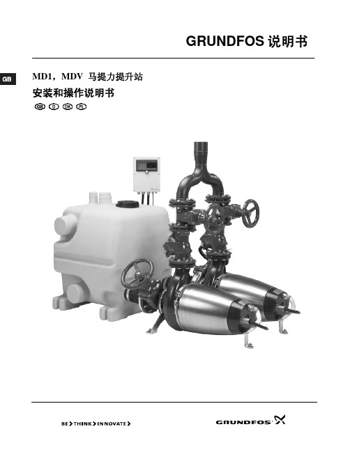
LCD 110 控制器控制 MD1 与 MDV 马提力提升站 泵的运行。 类型关键代码 LCD 110
3、产品说明
对MD1和MDV马提力提升站的说明可分为以下几节: 第4节,带有收集槽、泵和液位传感器的提升站描述 第5节,LCD110 控制器及其功能的描述。在第六 节:安装以及后面的几节中,根据需要将这些部 件进行描述。
4、提升站
气密性和水密性提升站带有两个泵。提升站的组成包括:
一个或两个400升的收集槽和一个手动隔膜泵,收集 槽上面带有所有必需的接口:进口管接口、排出管接 口、通风管,手动隔膜泵是一个附件。
马提力提升站 MD1 MDV
泵的类型 带有导槽叶轮的SE1泵 带有超级涡流叶轮的SEV泵
4
2、运输与贮存
如果长期贮存,泵和泵控制器必须要防止受潮、防止高温。 泵经过长期贮存之后,在投入使用之前,应该进行检 查。确保叶轮能够转动自如。 用泵上的油螺杆检查油液中是否含水。对于详细信 息,请参见泵的安装与使用说明。 对于详细信息,请参见泵的安装与使用说明。
铭牌泵位置规格防爆标志x为符合iec6007915可用于防爆设备的特殊要求型号说明改进阶段产品号生产地年代周系列号频率赫兹10速度分钟111电机输入功率p1千瓦12电机输出功率p2千瓦13机架尺寸14许可证标准x为符合atex可用于防爆设备的特殊要求15生产代码年周16最大流量每小时立方米17最大液体温度18绝缘等级19功率因数20额定电流21额定电压22额定电流23额定电压24重量mdv马提力提升站没有使用防爆电机
21
3
4
5 6 7 8 9 10 11 12 13
141
15 16 17 18 19 20 21 22 23 24
防爆排污泵使用说明书

技术标准Q/Q B F Y Q B-001-2016防爆潜水排污泵(隔爆型潜水电泵)BWQ系列Ex d ⅡB T4 Gb使用说明书2020-3-11编制贝德科技有限公司目录1、概述 (1)2、防爆(隔爆)原理 (1)3、防爆电机执行标准 (2)4、潜水排污泵执行标准 (3)5、使用范围 (4)6、机械特点 (4)7、技术说明 (5)8、辅助设施 (6)9、警告 (6)10、使用环境条件 (7)11、工作条件 (7)12、安全 (8)13、安装、调试 (8)14、警示 (9)15、安全保护装置及事故处理 (10)16、包装、运输、储存 (10)17、开箱检查 (11)18、随机附带配件 (11)19、环保及其他 (12)20、保修 (12)1、概述感谢您选用贝德科技有限公司的BWQ型隔爆型潜水电泵(潜水防爆排污泵)产品,以下简称“防爆排污泵”!2、防爆(隔爆)原理隔爆型“Exd”电机是防爆电机的一种形式,其原理是将设备在正常运行时,将可能产生火花、电弧或危险高温的部件置于隔爆外壳内,隔爆外壳能承受内部压力而不致损坏,并能保证内部的火焰气体通过间隙传播时,降低能量,不足以引爆壳外的气体。
3、防爆电机执行标准GB156 标准电压GB/T755 旋转电动机定额和性能(idt IEC 60034-1:1996)GB/T755.2 旋转电动机(牵引电动机除外)确定损耗和效率的试验方法(IEC 60034-2:1972)GB/T997 旋转电动机结构型式、安装型式及接线盒位置的分类(IM代码)(IEC 60034-7:2001)GB1971 旋转电动机线端标志与旋转方向(IEC 60034-8:2002)GB/T1993 旋转电动机冷却方法(IC代码)GB3836.1 爆炸性气体环境用电气设备第1部分:通用要求(eqv IEC 60079-0:1998)GB3836.2 炸性气体环境用电气设备第2部分:隔爆型“d”(eqv IEC 60079-0:1990)GB/T4772.1 旋转电动机尺寸和输出功率等级第1部分:机座号56~400和凸缘号55~1080(IEC 60072-1:1991)GB/T4942.1 旋转电动机整体结构的防护等级(IP代码)分级(IEC 60034-5:2000)GB10068-2008 轴中心高为56mm及以上电动机的机械振动的测量、评定及限值(idt IEC60034-14:1996)GB10069.3 旋转电动机噪声测定方法及限值第3部分:噪声限值(IEC 60034-9:1988)GB18613 中小型三相异步电动机能效限定值及能效等级JB/T8158 电压为660V及以下单速笼型三相异步电动机的起动性能IEC60034-12 旋转电动机第12部分:单速三相笼型异步电动机起动性能4、潜水排污泵执行标准GB/T 5013.4 额定电压450/750 V及以下橡皮绝缘电缆第4部分:软线和软电缆GB/T 1348 球墨铸铁件(GB/T 1348—2009,ISO 1083:2004,MOD)GB/T 2828.1 计数抽样检验程序第1部分:按接收质量限(AQL)检索的逐批检验抽样计划(ISO 2859-1:1999, IDT) GB/T 5013.4额定电压450/750 V及以下橡皮绝缘电缆第4部分:软线和软电缆(GB/T 5013. 4— 2008, IEC 60245-4 : 2004, IDT)GB/T 9239.1机械振动恒态(刚性)转子平衡品质要求第1部分:规范与平衡允差的检验 (GB/T 9239.1—2006,ISO 1940-1 :2003,IDT) GB/T 9439灰铸铁件G B10395.8农林拖拉机和机械安全技术耍求第8部分:排灌泵和泵机组G B 10396农林拖拉机和机械、草坪和园艺动力机械安全标志和危险图形总则(G B 10396— 2006,I S O11684:1995,M O D)G B/T 12785潜水电泵试验方法G B/T13306标牌G B/T 17241.6整体铸铁法兰J B/T 5673农林拖拉机及机具涂漆通用技术条件J B/T 6880.1〜6880.3泵用铸件J B/T 7593Y系列高压三相异步电机计数条件J B/T 8735.2额定电压450/750 V及以下橡皮绝缘软线和电缆第2部分:通用橡套软电缆J B/T 8735. 3额定电压450/750 V及以下橡皮绝缘软线和电缆第3部分:橡皮绝缘编织软电线J B/T 50080潜水电泵可靠性考核评定方法J B/Z 293交流高压电机定子绕组子绕组匝间绝缘试验规范5、使用范围5.1、化工企业、企业单位废水排放与提升;5.2、一体化预制泵站提升系统;5.3、城市污水处理厂排放系统。
污水处理泵安装和维修手册说明书
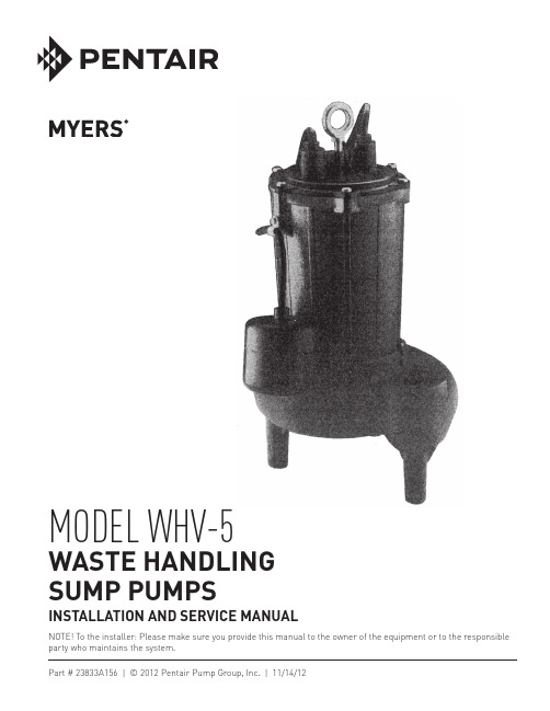
NOTE! To the installer: Please make sure you provide this manual to the owner of the equip m ent or to the responsible party who maintains the system.MODEL WHV-5WASTE HANDLING SUMP PUMPSINSTALLATION AND SERVICE MANUALPart # 23833A156 | © 2012 Pentair Pump Group, Inc. | 11/14/12CALIFORNIA PROPOSITION 65 WARNING:This product and related accessories contain chemicals known to the State of California to cause cancer, birthdefects or other reproductive harm.The WHV-5 series waste handling pumps are single phase 1/2 HP. Pumps have plug-in cords to operate as a manual pump by plugging directly into a grounded receptacle or into series plug of switch cord for automatic operation. Cords are furnished in 20' lengths. Plug is cut off when pump is used for duplex operation so as to connect directly to terminal block in control box. Also available are pumps with attached control floats for automatic operation.LEVEL SWITCHESWHV-5 manual pumps must be used with separate level controls for automatic operation. Switchesare sold and packaged separately and come with complete installation instructions.WHV-5 automatic pumps have their own attached control float switches.APPLICATIONSThe WHV-5 series waste handling pumps are designed for residential and commercial applications and will handle all wastewater, paper and other material normally found in sewage. Pump will handle 2" diameter solids. Not intended to pump large rags or mop heads.PIPINGPump case is fitted with 2" NPT female thread for 2" standard pipe.Pipe can be galvanized steel or schedule 80' plastic pipe. Schedule 40 plastic pipe can be used with proper cement adapters.CHECK VALVEA 2" check valve must be used at pump discharge. This should be a free-flow valve that will easily pass solids. The Myers CV-200 valve is designed especially for this service.INSTALLATIONThe WHV-5 waste handling pump is always installed in a gas tight sump basin. Myers offers complete packaged basin systems for simplex and duplex operation. Packaged basin systems include all parts except pump, level control, check valve, pipe and duplex control box. The WHV-5 pumps should be used in 24" dia. or larger basins. Do not use WHV-5 in an 18" diameter basin.SIMPLEX BASINThe B20-3036 basin package is for 1/2 HP pumps and has a 30" x 36" fiberglass basin with a steel basin cover and two cast iron pump covers. One cover is blank, for installation of second pump at later date if required, other cover has flange for 2" or 3" discharge pipe and has flange for mounting switch. Basin has 3" vent flange and inlet flange for 4-1/2" O.D. plastic pipe. This basin gives extra storage capacity needed for the larger pumps.DUPLEX BASINThe B20-3036D and B30-3036D basin systems are for duplex operation. This system has a 30" x 36" fiberglass basin with steel basin cover that supports two separate cast iron covers. Covers have sealing flange for discharge pipe either 2" or 3" as ordered. Covers also have mounting flanges for switches. Basin has 3" vent flange and inlet flange for 4-1/2" O.D. plastic pipe. An inlet flange for 6-5/8" O.D. plastic pipe, catalog number 1F-600 is also available. Inlet flanges are shipped loose for mounting in the field at inlet height required.SUMP COVERSMyers offers separate pump covers for simplex and duplex systems to be used with existing basin as a replacement, or with customer basin.Cover BC20-30D is for duplex system in 30" diameter basin with flange for 2" discharge pipe.Cover BC30-30D is for duplex system in 30" diameter basin with flange for 3" discharge pipe.With separate cover, the steel basin cover must be sealed to basin top with caulking compound. All covers include switch mounting flange and 3" vent flange.INSTALLING BASIN SYSTEMSThe sump basin is usually installed at time of pouring cement floor so that it can be cemented in place, level with the floor.Pumps are installed after construction is completed. Covers should be left on basin until after construction, so trash will not accumulate in basin.Check basin before installing pump and removeany rocks, cement chunks or other trash that could damage pump.23833A156 11/08/122Inlet flange is installed in the field and hole cut in basin at height required. More than one inlet flange can be used if required to bring extra lines into basin.CAUTION – Before installing pump in basin, turn pump on side and turn impeller with screwdriverin slotted shaft. Impeller must turn free on this test. Pump cord is sealed through cover with split rubber bushing.INSTALLING CHECK VALVEThe check valve is always installed in horizontal position to prevent solids from settling on top of clapper, causing clogging. A union and gate valve are recommended for use in discharge pipe to provide easy removal of pump.STARTING PUMP – SIMPLEX SYSTEM, AUTOMATIC PUMP1. Plug pump cord into 115 or 230 volt groundedreceptacle. The 230 volt receptacle has in-lineblade openings so that 115 volt plug cannot beplugged in.CAUTION – Never cut off grounding pins or use an adapter to plug into an ungrounded receptacle.2. Run water into sump until control turns on pump.Allow pump to operate until level drops, turningpump off.3. Run pump through several cycles to check switchoperation.4. If pump runs but does not deliver water, stopand start pump several times by unplugging andplugging in cord to clear air.Also, make sure the check valve is installedproperly, with flow arrow in the correct direction.Check elevations of discharge piping that theheight of the discharge is not greater than the total head capability of the WHV-5.5. If pump does not start at all, the trouble could bein the wiring, float switch, or the pump itself. STARTING PUMP WHV-5P (AUTOMATIC) USING MECHANICAL SWITCH WITH SERIES PLUG – SIMPLEX SYSTEM1. These pumps have a mechanical (mercury-free)float switch with a 10 ft. or 20 ft. cord with a 115volt or 230 volt series piggyback plug with switch mounted to the pump.2. Plug the switch cord plug into a proper voltage,properly grounded outlet.3. Plug the pump power cord into the back of theswitch cord.4. Tape the cords to the discharge pipe every 12".5. Run water into sump until pump starts. Be suredischarge line valve is open.6. Allow pump to operate through several on/offcycles.SETTING LEVEL CONTROLS – SIMPLEXSYSTEM WITH CONTROL PANELThree FLC mercury floats are used for simplexoperation. Cords from these controls must be marked so they can be connected to proper terminals in thecontrol box.The turn ON float should be set so that the water level raises at least to the top of the WHV-5 pump’s motorhousing before the pump turns on. With the WHV-5setting on the basin bottom, this height would be 14"minimum above the bottom of the basin. The settingof the ON float may be set as high as 6" below thebottom of the inlet pipe coming into the basin.Set the OFF float such that there is 6 to 7" of waterremaining in the basin. The water level should notdrop below the junction point of the WHV-5 volutecase and motor housing.The HIGH WATER (alarm) float should be set so thatthe water level is 4" above the level at which the pump turns on.STARTING PUMP – SIMPLEX SYSTEMWITH CONTROL PANEL1. Turn HAND-OFF-AUTO switch to OFF positionand close circuit breaker. Turn HAND-OFF-AUTOswitch to the AUTO position and run water into thesump or basin.2. When water level reaches the ON float switch, thepump should start and run. Yellow indicator lighton the panel will be illuminated. Pump will lowerwater level to the OFF float switch and the pumpwill stop.3. If the float switches are not set at the correctheights to result in the water levels as describedabove, turn the HAND-OFF-AUTO switch to OFFand adjust the float switches heights. RepeatSteps 1 and 2.4. If for any reason the water level reaches the HIGHWATER float, the alarm light or buzzer will beactivated. Alarm will stop as soon as level dropsbelow the HIGH WATER float.5. If pump operates as described, set HAND-OFF-AUTO switch to AUTO position and pumps areready for service.6. If pumps do not operate properly, make checks,as given in Steps 4 and 5, of STARTING PUMP,SIMPLEX SYSTEM, AUTOMATIC PUMP. SetHAND-OFF-AUTO switch to HAND position tocheck operation of the pump.23833A156 11/08/1237. Check for electrical trouble – explained in thecontrol box instructions. A competent electricianshould make checks in the control box to locatetrouble.CAUTION – NEVER WORK ON PUMPS ORCONTROL BOX UNTIL CIRCUIT BREAKER ISTURNED OFF.SETTING LEVEL CONTROLS – DUPLEX SYSTEM WITH CONTROL PANELFour FLC mercury floats are used for duplex operation. Cords from these controls must be marked so they can be connected to proper terminals in the control box.The turn ON float should be set so that the water level raises at least to the top of the WHV-5 pump’s motor housing before the lead pump turns ON. With the WHV-5 setting on the basin bottom, this height would be 14" minimum above the bottom of the basin. The setting of the ON float may be set as high as 12" below the bottom of the inlet pipe coming into the basin.Position the lag pump ON (override) float switch about 6" above the lead pump ON float.Set the OFF float such that there is 6 to 7" of water remaining in the basin. The water level should not drop below the junction point of the WHV-5 volute case and motor housing.The HIGH WATER (alarm) float should be set so that the water level is 4" above the level at which the lag pump turns on.STARTING PUMP – DUPLEX SYSTEM WITH CONTROL PANEL1. Turn both HAND-OFF-AUTO switches to OFFposition and close circuit breaker.2. Turn both HAND-OFF-AUTO switches to the AUTOposition and run water into the sump or basin.3. When water level reaches the first ON float switch,one pump should start and run. Yellow indicatorlight on the panel will be illuminated for theoperating pump.Pump will lower water level to the OFF float switch and the pump will stop.4. Run water into the sump again. When water levelreaches the first ON float, the opposite pump will start. The yellow light will show which pump isoperating. 5. This cycle will continue and pumps will alternateon successive cycles.6. If excessive flow enters the basin that is more thanone pump can handle, the sump level will rise and activate the override float, which will start bothpumps and activate the alarm.7. The same condition can occur if one pump failsfor any reason. Then level will rise to the override float, and the good pump will start and operateuntil failed pump is replaced or repaired. If for any reason level reaches fourth float, alarm light orbuzzer will be activated. Alarm will stop as soon as level drops below the alarm float.8. To check override operation, turn both HAND-OFF-AUTO switches to OFF position and fill basin until level is above override float (3rd float).9. Turn both HAND-OFF-AUTO switches to AUTOposition and both pumps should start.10. R epeat this operation with one pump off, whichwill duplicate a failed pump condition. In this case, when level reaches override float, the pump thatis in the ON position should start. Operation willcontinue on this one pump.11. l f pumps operate as described, set both HAND-OFF-AUTO switches to AUTO position and pumps are ready for service.12. l f pumps don’t operate properly, make checks asgiven for simplex system. Use HAND-OFF-AUTO switch in HAND position to check operation ofeach pump.13. C heck for electrical trouble given in the control boxinstructions.A competent electrician should make checks in thecontrol box to locate trouble.CAUTION – NEVER WORK ON PUMPS ORCONTROL BOX UNTIL CIRCUIT BREAKER ISTURNED OFF.CHECK POINTS IF PUMP DOES NOT RUN AND OPERATE PROPERLY1. Be sure fuse is not blown or circuit breaker is nottripped. Pump should have separate circuit withits own fuse or breaker. If on circuit with otherequipment, nuisance tripping may occur.2. CAUTION – Always unplug pump cord beforeremoving pump from sump basin. Removepump and check for plugged inlet or trashstuck in pump. Be sure pump impellers turnfreely after removing any trash.3. If pump does not operate after cleaning, statormay be damaged or burned out. Occasionally,lightning may damage a motor.23833A156 11/08/124523833A156 11/08/126WHV-523833A156 11/08/127ReferencePart Number Description Qty.121929A002Bolt, Eye 3/8"-161224472D001Cap1305876A125O-Ring, 6-1/8" x 5-7/8" x 1/8"1419099A023Screw, Machine 1/4"-20 x 7/8"6509822A006Screw, #10-24 x 1/2" (Auto Pump Only)1617190A008Clamp, Cable (Auto Pump Only)1717190A004Tie, Cable1824948C000Plate with Bearing 1920892A133Sleeve 3/4" I.D. x 3 Lg.11005030A163Washer, Teflon ® 1/2" x 1" x 1/6"11105030A173Washer, SST 1/2" x 1" x 1/32"1–See Chart Housing with Stator 11224946D000Housing Only 113See Chart Stator Only 114See Chart Rotor with Shaft 11512558A030Ring, Retaining 11608565A013Bearing, Ball11714525A010Seal, Shaft, Type 6 (Shown)1–22447A000Seal, Shaft, Type 21 (Not Shown)1ReferencePart Number DescriptionQty.1813321A009Screw, Set 5/16"-18 x 3/4"41924945C000Impeller 12024947D000Case, Volute 12109859A800Wire, Jumper 12209859A801Wire, Ground 22323838A000Capacitor 12420333A004Clip, Capacitor22505434A054Screw, 10-24 x 1/2"42611009A002Oil Transformer (1 Qt. Can)22706106A037Screw, 10-24 x 3/8"12805022A054Plug, Pipe 1/4" NPT 129See Chart Cord, Electric13024448A000Plug, Nut (Manual Pump & P Series)13105030A213Washer (Manual Pump & P Series)13224449A000Plug, Jumper (Manual Pump & P Series)13321813B120Control, Float (Auto Pump for A Series)13414743A000Emblem, Myers 13518812A157Instructions13819109A018Nut, Hex 3/8"-16UNC1M = Manual A = Automatic P = PiggybackPump Catalog No.Pump Engr. No.Housing with Stator (13) Stator Only (14) Rotor with Shaft (19) Impeller (29) Cord (33) Control WHV-5M-1124949D00024946D100K 24987B00024989B00024945C00021628B018–WHV-5M-2124949D00124946D101K 24987B00124989B00024945C00021628B019–WHV-5A-1124949D00224946D100K 24987B00024989B00024945C00021628B01821813B120WHV-5A-2124949D00324946D101K 24987B00124989B00024945C00021628B01921813B120WHV-5P-124949D90024946D100K 24987B00024989800024945C00021628B04121813B130WHV-5PC-l 24949D90124946D100K 24987B00024989800024945C00021628B01821813B131WHV-5P-224949D90224946D101K 24987B00124989B00024945C00021628B04221813B132WHV-5PC-224949D90324946D101K24987B00124989B00024945C00021628B01921813B133DIMENSIONSPARTS LISTONOFFModel Voltage Electrical Current – Amperes Flow – GPM04080120Locked RotorWHV-5M-111157.07.38.49.521WHV-5A-111157.07.38.49.521WHV-5M-21230 3.5 3.7 4.2 4.810.5WHV-5A-21230 3.5 3.7 4.24.810.51101 MYERS PARKWAY 490 PinEbuSh RoAd, unit #4 AShLAnd, ohio, uSA 44805 CAMbRidGE, ontARio, CAnAdA n1t 0A5 419-289-1144 800-363-PuMP Warranty Rev. 12/13STANDARD LIMITED WARRANTYPentair Myers ® warrants its products against defects in material and workmanship for a period of 12 months from the date of shipment from Pentair Myers or 18 months from the manufacturing date, whichever occurs first – provided that such products are used in compliance with the requirements of the Pentair Myers catalog and technical manuals for use in pumping raw sewage, municipal wastewater or similar, abrasive-free, noncorrosive liquids.during the warranty period and subject to the conditions set forth, Pentair Myers, at its discretion, will repair or replace to the original user, the parts that prove defective in materials and workmanship. Pentair Myers reserves the right to change or improve its products or any portions thereof without being obligated to provide such a change or improvement for prior sold and/or shipped units.Start-up reports and electrical schematics may be required to support warranty claims. Submit at the time of start- up through the Pentair Myers website: /startupform/startupform.asp?type=m. Warranty is effective only if Pentair Myers authorized control panels are used. All seal fail and heat sensing devices must be hooked up, functional and monitored or this warranty will be void. Pentair Myers will cover only the lower seal and labor thereof for all dual seal pumps. under no circumstance will Pentair Myers be responsible for the cost of field labor, travel expenses, rented equipment, removal/reinstallation costs or freight expenses to and from the factory or an authorized Pentair Myers service facility.this limited warranty will not apply: (a) to defects or malfunctions resulting from failure to properly install, operate or maintain the unit in accordance with the printed instructions provided; (b) to failures resulting from abuse, accident or negligence; (c) to normal maintenance services and parts used in connection with such service; (d) to units that are not installed in accordance with applicable local codes, ordinances and good trade practices; (e) if the unit is moved from its original installation location; (f) if unit is used for purposes other than for what it is designed and manufactured; (g) to any unit that has been repaired or altered by anyone other than Pentair Myers or an authorized Pentair Myers service provider; (h) to any unit that has been repaired using non factory specified/oEM parts.Warranty Exclusions: PEntAiR MYERS MAKES no EXPRESS oR iMPLiEd WARRAntiES thAt EXtEnd bEYond thE dESCRiPtion on thE FACE hEREoF. PEntAiR MYERS SPECiFiCALLY diSCLAiMS thE iMPLiEd WARRAntiES oF MERChAntAbiLitY And FitnESS FoR AnY PARtiCuLAR PuRPoSE.Liability Limitation: in no EVEnt ShALL PEntAiR MYERS bE LiAbLE oR RESPonSibLE FoR ConSEQuEntiAL, inCidEntAL oR SPECiAL dAMAGES RESuLtinG FRoM oR RELAtEd in AnY MAnnER to AnY PEntAiR MYERS PRoduCt oR PARtS thEREoF. PERSonAL inJuRY And/oR PRoPERtY dAMAGE MAY RESuLt FRoM iMPRoPER inStALLAtion. PEntAiR MYERS diSCLAiMS ALL LiAbiLitY, inCLudinG LiAbiLitY undER thiS WARRAntY, FoR iMPRoPER inStALLAtion. PEntAiR MYERS RECoMMEndS inStALLAtion bY PRoFESSionALS.Some states do not permit some or all of the above warranty limitations or the exclusion or limitation of incidental or consequential damages and therefore such limitations may not apply to you. no warranties or representations at any time made by any representatives of Pentair Myers shall vary or expand the provision hereof.。
污水处理设备使用说明书
污水处理设备使用说明书使用说明书本使用说明书旨在提供关于污水处理设备的使用方法和注意事项,以确保设备的正常运行和维护。
请在使用前仔细阅读本手册,并按照指示操作。
一、设备概述污水处理设备是一种用于处理工业或生活中产生的污水的技术装置。
本设备采用一系列物理、化学和生物方法,将污水中的杂质和污染物去除,最终达到排放标准。
二、安装和运输1. 设备运输时应保持平稳,避免碰撞和摔落,以免造成设备损坏。
2. 安装时需确保设备底部与地面平齐,设备周围无堵塞物,保证设备正常运作。
三、设备操作1. 启动设备前,确保电源连接稳定并故障检测正常。
2. 污水处理设备通常具备自动化控制系统,操作前请熟悉控制面板的功能和指示信息。
3. 根据设备的工艺流程,逐一操作处理单元。
通常包括预处理、调节和生化处理等阶段。
4. 定期进行设备的清洗、检查和维护,确保各零部件的正常工作。
5. 当设备长时间停用时,应及时关闭电源,并将设备进行完全清洗和封存,以防止污染物附着或产生堵塞。
四、注意事项1. 使用设备过程中需不断监测进水和出水的水质,确保排放达到国家排放标准,避免对环境造成污染。
2. 当设备发生故障或异常时,应及时停止操作,并联系专业人员进行检修。
3. 切勿随意改变设备的工作参数和设置,防止对设备正常运行产生不利影响。
4. 使用设备过程中需注意人身安全,避免直接接触到污水和化学药剂,应戴好防护装备。
5. 使用设备过程中应做好日常清洁卫生工作,保持设备的良好环境和卫生状况。
6. 请按照设备制造商提供的使用说明和维护手册进行操作和维护。
五、故障排除1. 设备故障时,请仔细阅读设备制造商提供的故障排除指南,按照指引进行处理。
2. 如无法解决故障,请立即联系售后服务部门,并提供详细的故障信息和设备型号。
六、维护保养1. 设备运行一段时间后,应定期进行维护保养,包括设备的清洗、润滑和更换耗损部件等。
2. 严格按照设备维护手册的要求进行维护,定期检查设备各部位的紧固情况和电气连接。
公司污水泵操作规程

污水泵操作规程一、启动前操作1、检查机油油位(必须使发动机在水平位置),低于油尺下限的及时补充。
2、检查燃油油位。
3、检查空气滤清器。
4、检查进水管、排水管是否连接紧固。
5、检查水泵是否加水。
6、检查进水管过滤器是否安装牢固,有无穿洞及杂物赌塞。
二、启动和操作1、将燃油阀开至(ON位置)。
2、关闭阻风门(只限冷启动)。
3、将发动机开关打开到(ON位置)。
4、将节气门控制杆慢慢地移向左边。
5、轻轻拉起启动手把直到感到有阻力,然后快速拉起。
6、当发动机暖车后,逐渐打开阻风门。
7、将节气门设定在预定的转速。
三、停机操作1、将节气门控制杆移到最右边。
2、将发动机开关打到(OFF位置)。
3、将燃油阀门关至(OFF位置)。
四、维护保养1、冬季将泵内积水下水管线及上水管线放净,以免冻坏。
2、使用过程中定期更换发动机机油。
3、使用过程中定期清洗空气滤清器。
4、每年进行叶轮检查、进水阀检查、火花塞维护、气门间隙调整、燃烧室清洁。
5、每运转100小时清洗一次火花消除器。
6、每2年更换一次燃油管。
五、注意事项1、操作人员查看泵的出水情况。
2、发动机启动时,启动把手拉出后不要猛松手,要轻轻放回,以免损坏启动器。
3、在没有安装空气滤清器时,不要启动发动机,以免脏物、灰尘通过化油器被吸入发动机口,将导致发动机磨损加快。
4、泵内没有加水时,不要运行污水泵,以免过热,将损坏污水泵密封圈。
5、机油不足时严禁运转污水泵,以免损坏发动机。
污水泵抽海水或有腐蚀性污水时,用完后立即用它抽一次清水,以减少腐蚀和冲掉沉淀物。
6、发动机正在运转,消声器将非常热,操作者不要碰触消声器,以免烫伤。
在设备运转时,不要离开,随时听设备有无异声,如有要立即停机。
- 1、下载文档前请自行甄别文档内容的完整性,平台不提供额外的编辑、内容补充、找答案等附加服务。
- 2、"仅部分预览"的文档,不可在线预览部分如存在完整性等问题,可反馈申请退款(可完整预览的文档不适用该条件!)。
- 3、如文档侵犯您的权益,请联系客服反馈,我们会尽快为您处理(人工客服工作时间:9:00-18:30)。
中国船级社质量认证公司
通过质量认证 GB/T19001-2000
CGW型
船用排污泵
使用说明书
执行标准:GB/T3523-1993
泰州市霞鑫机械制造有限公司
TAIZHOU XIAXIN MACHINE MANUFACTURE CD.,LTD.
一、概述
泰州市霞鑫机械制造有限公司
一、用途
CGW型系列船用排污泵具有结构紧凑,性能优良,安装方便,体积小等特点。
该泵用于该系列泵适用于输送含有直径为泵口径1/3的固体物块和含有长度为泵口径5倍的纤维材料,温度在85℃以下的生活污水、工业废水、油污水、淡水或海水。
是污水处理设备的最佳配套泵。
二、结构
CGW型泵主要由泵体、泵架、叶轮、泵轴、密封环、机械密封、电机等部件组成,泵轴和电机采用直联型式,叶轮直接用叶轮螺母固定在轴端部。
轴封采用机械密封,减少了泄漏,提高了泵的效率。
三、结构图
9.电机10.轴11.紧定螺钉12.甩水圈13.机械密封14.密封环
四、泵的使用、维护保养
为了使泵能够正常运转延长使用寿命,减少故障,必须正确地安装使用及维护保养。
1、安装前应先检查电机、水泵有无损坏,连接螺丝有无松动现象。
2、安装时,泵的进出口法兰中心应与进出水管道中心一致。
且泵法兰不得承受管道的重量。
3、试验启动,检查电机旋转方向是否与泵体上转向牌箭头指向一致,试验时间不超过1分钟。
4、关闭出水管闸阀及压力表旋塞。
5、从泵体上部螺孔,向水泵和吸水管内灌满水。
6、上述过程完成后,启动电机并打开压力表旋塞。
7、水泵达到规定转数后,压力表显示适当压力,然后打开真空表旋塞,并逐渐打开出水管路闸阀,使流量达到所需范围。
8、工作时如发现不正常声音,应立即停机检查。
9、水泵停止工作时,应慢慢关闭出水管路闸阀,关闭真空表旋塞,并停止电动机,然后关闭压力表旋塞。
10、水泵工作一段时间后,应定期检查叶轮与密封环配合处间隙,不能磨损过大。
其间隙在直径方向的最大值为2毫米,如超过时应更换密封环。
11、水泵长期不工作时,水泵应拆开,将零件上的水擦干,并在加工面处涂上防锈油,妥善保存。
七、供货范围
1、泵机组(包括泵、电机等)
2、备件(根据定货要求供应)
3、装箱资料
产品合格证书
产品装箱清单
安装使用说明书(本文件)。