
纳普科技PM9806T多通道数字功率计参数表
PM9806T电参数测量仪(六级能效型)
产品特点:
1、LED数码屏显示:电压、电流、功率、功率因数/频率/谐波
2、所有测量均为真有效值Trms
3、自动量程
4、基本精度:0.5级
5、对外界杂讯具有高免疫力
6、支持数据锁定
7、可设定电流和功率上下限值报警功能;PASS灯绿色,NG灯红色,方便判别
应用领域:
·家用电器的能耗测试
·空调器的能耗测试
·照明电器的功耗
·LED灯具的功耗测试
·电机及马达的测试
·充电器及开关电源的测试
接线方式单相
显示LED数码屏
测量项目电压V、电流A、有功功率W、功率因数PF、频率Hz、1-50次谐波
电压量程5-600V AC(量程自动切换)峰值电压:700V AC最小测试电压:5V AC(低于5V可定制)电流量程0.05mA-5A AC(量程自动切换)峰值电流:6.5A AC最小测试电流:0.05mA AC
功率量程0.001W-3kW(适用于待机功耗测试)
功率因素量程0.001-1.000
计算方式:瓦特(W)÷[电压(V)×电流(A)]=功率因数(PF)
频率量程45-65Hz
通讯接口标配RS232或RS485,选配继电器输出功能基本精度±(0.4%读数+0.1%量程+1字)
测量速度5次/秒
输入阻抗≥1MΩ(所有电压档)
电源供应85-265V AC50/60Hz,85-265V DC
体积与重量355mm长×223mm宽×112mm高,≈1.7kg
附件电源线、说明书、保修卡、通讯线、软件光盘。
附表1 GSK980TD参数表
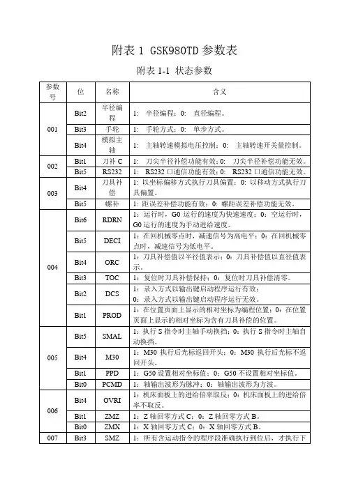
附表1 GSK980TD参数表附表1-1 状态参数MD4 MD2 MD1 开机操作方式0 0 0 录入方式0 0 1 自动方式0 1 0 机械回零0 1 1 编辑方式1 0 0 手轮方式1 0 1 手动方式附表1-2数据参数参数号名称含义015 CMRXCMRX 、CMRZ:X、Z轴指令倍乘系数。
设定范围为:1~255。
016 CMRZ017 CMDX CMDX、CMDZ:X、Z轴指令分频系数。
设定范围为:1~255 。
S:最小指令输出单位ZM:丝杠端皮带轮的齿数α:一个脉冲当量电机转动的角度ZD:电机端皮带轮的齿数L:丝杠导程018 CMDZ019 THDCH THDCH:螺纹切削时的退尾长度。
螺纹退尾宽度=THDCH×0.1×螺纹导程设定范围:0~255021 主轴摸拟调正数据主轴最高速度指令模拟电压输出为10V时电压偏置补偿值。
设定范围:-2000~2000(单位:毫伏)022 RPDFX RPDFX:X轴最高快速移动速度(半径值)。
设定范围:10~3825000(单位:毫米/分)023 RPDFZ RPDFZ:Z轴最高快速移动速度。
设定范围: 10~7650000(单位:毫米/分)024 LINTX LINTX、LINTZ:X、Z轴快速移动时,线性加减速时间常数值。
设定范围:0~4000(单位:毫秒)025 LINTZ026 THRDT THRDT:螺纹退尾时短轴的加减速时间常数。
设定范围:0~4000(单位:毫秒)027 FEDMX FEDMX:X、Z轴切削进给上限速度。
设定范围:10~8000(单位:毫米/分)028 THDFL THDFL:螺纹切削X、Z轴的起始速度。
设定范围:6~8000(单位:毫米/分)029 FEEDT FEEDT:切削进给和手动进给时指数加减速时间常数。
设定范围:0~4000(单位:毫秒)。
特克ト尼克 PSM3000、PSM4000 和 PSM5000 系列 RF 和微波功率传感器 表计数

RF and Microwave Power Sensors/MetersTektronix PSM3000,PSM4000,and PSM5000Series DataSheetFeatures &Bene fitsKey Performance Speci fications8GHz,18GHz,20GHz,and 26.5GHz Models Models Available with N and 3.5mm ConnectorsDynamic Range as Low as –60dBm and as High as +20dBm Uncertainty as Low as 2.6%Reading Rates up to 2000Readings/sFeaturesMeters are Calibrated over Full Temperature Range –No zero or cal needed before making measurements,saving time and avoiding poor-quality dataAverage Power,Duty Cycle Corrected Pulse Power,and Measurement Logging on All ModelsIncluded Applications run under Microsoft Windows Power Meter ApplicationHigh-speed Logging ApplicationLabVIEW Drivers and Programming Examples for Most Common Windows Programming Environments are Available for Automated System Support Max Hold and Relative Measurement ModesOffset,Frequency Response,and 75ΩMinimum Loss Pad Correction Flexible Averaging Modes for Quick,Stable Measurements TTL Trigger Input and Output allow Synchronization with External InstrumentsPass/Fail Limit Mode Compact SizeThe PSM3000Series offers True Average Power Measurements that Give Accurate Results Regardless of Signal Shape or Modulation The PSM4000and PSM5000Series offer:Pulse Power,Duty Cycle,Peak Power,and Crest Factor MeasurementsMeasure Peak,Average and Minimum Power on Bursts with Adjustable Offset and Duration The PSM5000Series includes a Pulse Pro filing Application for Making Measurements on Repetitive,Pulsed SignalsBuilds and Displays a Trace of the Pulse EnvelopeFull-trace and Gated Measurements including Pulse,Peak and Average Power,Overshoot,Crest Factor,Rise and Fall Time,Pulse Width,Pulse Repetition Frequency,Duty CycleStatistical Measurements on the Trace Data,such as Complementary Cumulative Distribution Function (CCDF),and Probability Density Function(PDF)1981Data SheetApplicationsGeneral-purpose RF and Microwave Average Power MeasurementsCharacterization of Repetitive Pulsed Signals,such as Navigation,Weather,and other RadarPeak and Average Power Measurements on Modulated Signals such as GSM,CDMA,WCDMA,HSPA,WiMAX up to10MHzPeak and Average Power Measurements of Modulated PulsedCommunications SignalsLevel Control Feedback for Signal SourcesValidation and Characterization of Power Amplifiers,Switches,and Other RF and Microwave ComponentsService,Maintenance,and Installation of DTV,Cellular,MicrowaveRadio Link,and Radio Broadcast TransmittersVerification and Calibration of Test Equipment and Systems3-year WarrantyCapable,Compact Power Sensors/MetersThe PSM3000,PSM4000,and PSM5000Series are compact power sensors/meters that deliver fast,accurate RF and microwave power measurements.A broad range of CW and pulse modulation measurements are available,depending on the series you choose.Each meter comes with Windows Power Meter application software for controlling the meter,displaying readings,and recording data.The combination of the sensor/meter and PC provides a complete solution,eliminating the need for a separate,dedicated meter mainframe.No Meter Mainframe RequiredWith the included power meter application software,familiar meter controls are available at the click of a mouse and readings are presented right on your PC screen.Familiar Windows pull-down menus provide additional controls.Data is immediately available on the PC for further analysis and documentation.The meters communicate with the PC using standard USB2.0protocols and cables for plug-and-play ease of use.Integrate High-speed Power Measurements Into Your TestingTektronix PSM Series power sensors feature the industry’s fastest measurement speed(2000readings/s).This can significantlyreduce Figure1–Software presents familiar controls and measurement presentation.test times and provide dynamic power measurement information thatwas previously unavailable.An included High-speed Logging Application provides a mechanism for getting this data into your PC for analysis.For custom test applications,you can communicate with the sensors using LabVIEW,or using a fully documented API.Example programs are provided for the most commonly used development environments.The communications library allows your program to communicate with up to12sensors,eliminating the need for costly switches.Tektronix real-time signal analyzers,arbitrary waveform generators,and oscilloscopes that use the Windows operating system can also be used to control the PSM Series sensor/meter and give you quick access to accurate power measurements.To allow synchronization with other measurement equipment all models include Trigger In and Trigger Out TTL signals.High-speed measurements,extensive programming tools,and synchronization features make these sensors versatile additions to your test setup.Industry-leading Performance for Demanding DesignsTektronix power sensors/meters come fully calibrated over their entire operating temperature range.Sensor zeroing and meter reference calibration have been eliminated,reducing setup time and helping to avoid inaccurate results.These meters provide accuracy you can count on for general-purpose CW,peak,pulse,and other modulated power measurements.Whether doing installation or maintenance on a wireless base station,production testing,or R&D for wireless components,the PSM Series products serve these needs with a wide dynamic range(–60dBM to +20dBm)and frequencies ranging from10MHz up to26.5GHz.RF and Microwave Power Sensors/Meters—Tektronix PSM3000,PSM4000,and PSM5000Series Select the Performance/Features to Meet YourNeedsPSM3000Series power sensors/meters provide true average powermeasurements,giving accurate power measurements independent of signalmodulation and bandwidth.The PSM4000Series delivers average power(CW)measurements,and adds pulse and peak power measurements forgathering basic data on pulsed RF and microwave signals.PSM5000Series power sensors/meters provide the same measurements as thePSM4000,and add pulse profiling capability for signal viewing andcharacterization in pulsed RF and microwave systems.Feature PSM3000Series PSM4000SeriesPSM5000SeriesFrequency Range10MHz to26.5GHz10MHz to20GHz50MHz to20GHzDynamic Range–55dBM to+20dBm –60dBm to+20dBM–60dBm to+20dBmMeasurement Speed 2000readings/s2000readings/s2000readings/sMeasurementsTrue AveragePowerXAverage(CW)PowerX XDuty CycleCorrected PulsePowerX X XPeak Power,PulsePower,Duty CycleX XPeak and AverageBurst PowerX XMeasurementLoggingX X XPulse Width,Rise/Fall,Overshoot,DroopXTime GatedMeasurementsXPulse Waveform Display with Markers XFigure2–Pulse profiling software enables a thorough analysis of pulse characteristics.A Broad Range of Pulse EnvelopeMeasurementsTektronix PSM5000Series products feature an easy-to-use,highperformance,pulse profiling,pulse(modulation),and CW power meter andsensor in one.The PSM5000Series product is specifically designed forapplications requiring time domain analysis of constant-envelope,repetitivepulsed signals.It performs time domain pulse measurements such asrise/fall time,overshoot,and droop that have typically required costly signalanalyzers.PSM5000Series sensors use an equivalent time-samplingtechnique to reconstruct repetitive,pulsed input signals.Repetitive pulseswith video bandwidths up to10MHz can be measured with an effectivesample rate of up to48MS/s.Performance You Can Count OnIn addition to industry-leading service and support,every PSM Series powersensor/meter comes backed with a three-year standard warranty.3Data SheetSpecificationsElectrical SpecificationsAll specifications apply over the full instrument operating temperature range unlessotherwise noted,after a20minute warm-up interval.PSM3000Series USB Power Meters(True Average)Characteristic PSM3110PSM3120PSM3310PSM3320PSM3510 Input Connector 3.5mm,male N-type,male 3.5mm,male N-type,male 3.5mm,male Frequency Range10MHz to8GHz10MHz to18GHz10MHz to26.5GHz Dynamic Range–55dBm to+20dBmVideo Bandwidth100Hz,typicalTotal Accuracy*1Total Uncertainty=2×√[(CF/2)2+(L/2)2+(N/2)2+(Z/√2)2+(Mm/√2)2+(T/√2)2]Calibration Factor Uncertainty(CF)10MHz to1GHz:2.5%1GHz to8GHz:2.4%10MHz to1GHz:1.8%1GHz to8GHz:1.7%10MHz to1GHz:2.5%1GHz to10GHz:2.4%10GHz to18GHz:2.7%10MHz to1GHz:1.8%1GHz to10GHz:1.7%10GHz to18GHz:1.9%10MHz to1GHz:2.5%1GHz to10GHz:2.4%10GHz to18GHz:2.7%18GHz to26.5GHz:3.7%Linearity Uncertainty(L)+15dBm to+20dBm: 3.0%–15dBm to+15dBm:2.5%–55dBm to–15dBm: 2.0%Noise Uncertainty(N)5second integration+10dBm to+20dBm:0.10%–15dBm to+10dBm:0.25%–30dBm to–15dBm:0.10%–40dBm to–30dBm:0.25%–50dBm to–40dBm:1.50%–55dBm to–50dBm:4.50%Zero Offset Power*2(Z)[(3.0nW at25°C)+|ΔT|×(0.15nW/°C)]+0.01nW/monthMatch*3 1.20:1VSWR(21dB Return Loss)10MHz to10GHz:1.20:1VSWR(21dB Return Loss)10GHz to18GHz:1.29:1VSWR(18dB Return Loss)10MHz to10GHz: 1.20:1VSWR(21dBReturn Loss)10GHz to26.5GHz: 1.29:1VSWR(18dBReturn Loss)Temperature Uncertainty (T)40°C<T≤50°C:2.00% 30°C<T≤40°C:0.75% 20°C<T≤30°C:0.00% 10°C<T≤20°C:0.75% 0°C<T≤10°C:2.00%*1Total uncertainty includes contributions from Calibration Factor Uncertainty(CF),Linearity Uncertainty(L),Noise Uncertainty(N),Zero Offset Uncertainty(Z),Mismatch Uncertainty,and Temperature Uncertainty(T).All error terms must be converted to percentages for Total Uncertainty(RSS)calculation.Mismatch Uncertainty(Mm)requires knowledge of source match and should be expressed as a percentage using the equation Mm=100×[(1±Γsource×Γsensor)2–1].*2Use the following formula to determine Zero Offset Uncertainty as a percentage:Z=(Zero Offset Power/Nominal Power)×100.*3Nominal impedance=50Ω.RF and Microwave Power Sensors/Meters—Tektronix PSM3000,PSM4000,and PSM5000SeriesPSM4000Series USB Power Meters(Average/Peak/Pulse)Characteristic PSM4110PSM4120PSM4320PSM4410Input Connector 3.5mm,male N-type,male N-type,male 3.5mm,male Frequency Range10MHz to8GHz10MHz to8GHz50MHz to18.6GHz50MHz to20GHz Dynamic Range10MHz to6GHz:–60dBm to+20dBm6GHz to8GHz:–50dBm to+20dBm–40dBm to+20dBmMaximum Peak-to-Average Ratio10MHz to6GHz:80dB6GHz to8GHz:70dB55dBInternal Video Bandwidth10MHz,typicalTimebase±50ppm,typicalSample Rate500kS/sAverage Power,Minimum PulseWidth500ns,typicalPeak Power,Minimum PulseWidth200ns,typicalTotal Accuracy*1Total Uncertainty=2×√[(CF/2)2+(L/2)2+(N/2)2+(Z/√2)2+(Mm/√2)2+(T/√2)2]Calibration Factor Uncertainty (CF)10MHz to100MHz:7.0%100MHz to500MHz:4.0%500MHz to8GHz:2.5%10MHz to100MHz:7.0%100MHz to500MHz:4.0%500MHz to8GHz:1.7%50MHz to500MHz:4.0%500MHz to10GHz:1.7%10GHz to18.6GHz:1.9%50MHz to500MHz:4.0%500MHz to12.5GHz:2.6%12.5GHz to18GHz:3.2%18GHz to20GHz:3.5%Linearity Uncertainty(L)10MHz to100MHz+15dBm to+20dBm:7.0%+10dBm to+15dBm:5.0%–60dBm to+10dBm:4.0%100MHz to2GHz+15dBm to+20dBm:7.0%+10dBm to+15dBm:5.0%–60dBm to+10dBm:3.0%2GHz to8GHz+15dBm to+20dBm:5.0%+10dBm to+15dBm:3.0%–60dBm to+10dBm:2.0%50MHz to100MHz+15dBm to+20dBm:7.0%–40dBm to+15dBm:5.0%100MHz to2GHz+15dBm to+20dBm:7.0% +5dBm to+15dBm:5.0%–40dBm to+5dBm:3.0%2GHz to20GHz+15dBm to+20dBm:6.0% +5dBm to+15dBm:4.0%–40dBm to+5dBm:2.0%Noise Uncertainty(N)1second integration+10dBm to+20dBm:0.22%(10MHz to100MHz)0.15%(100MHz to8GHz)–30dBm to+10dBm:0.22%(10MHz to100MHz)0.04%(100MHz to8GHz)–50dBm to–30dBm:0.22%(10MHz to100MHz)0.04%(100MHz to6GHz)0.15%(6GHz to8GHz)–60dBm to–50dBm:0.44%(10MHz to100MHz)0.15%(100MHz to6GHz)5second integration+10dBm to+20dBm:1.5%(50MHz to20GHz)–20dBm to+10dBm:1.0%(50MHz to20GHz)–30dBm to–20dBm:1.5%(50MHz to20GHz)–40dBm to–30dBm:7.0%(50MHz to18.6GHz)Zero Offset Power*2(Z)[(0.35nW at25°C)+|ΔT|×(0.025nW/°C)]+0.005nW/month50MHz to500MHz[(200nW at25°C)+|ΔT|×(10nW/°C)]+10nW/month500MHz to20GHz[(100nW at25°C)+|ΔT|×(5nW/°C)]+5nW/monthMatch*3 1.09:1VSWR(27dB Return Loss)1.15:1VSWR(23dB Return Loss)50MHz to10GHz:1.20:1VSWR(21dB Return Loss)10GHz to18.6GHz:1.29:1VSWR(18dB Return Loss)50MHz to10GHz:1.20:1VSWR(21dB Return Loss)10GHz to20GHz:1.29:1VSWR(18dB Return Loss)5Data SheetCharacteristic PSM4110PSM4120PSM4320PSM4410Temperature Uncertainty(T)40°C<T≤50°C:1.00%(plus1%,0dBm to10dBm;plus3%,10dBm to20dBm)30°C<T≤40°C:0.75%(plus1%,0dBm to10dBm;plus3%,10dBm to20dBm)20°C<T≤30°C:0.00%10°C<T≤20°C:0.75%(plus1%,0dBm to10dBm;plus3%,10dBm to20dBm)0°C<T≤10°C:1.00%(plus1%,0dBm to10dBm;plus3%,10dBm to20dBm)40°C<T≤50°C:6.00% 30°C<T≤40°C:3.00% 20°C<T≤30°C:0.00% 10°C<T≤20°C:3.00% 0°C<T≤10°C:6.00%*1Total uncertainty includes contributions from Calibration Factor Uncertainty(CF),Linearity Uncertainty(L),Noise Uncertainty(N),Zero Offset Uncertainty(Z),Mismatch Uncertainty,and Temperature Uncertainty(T).All error terms must be converted to percentages for Total Uncertainty(RSS)calculation.Mismatch Uncertainty(Mm)requires knowledge of source match and should be expressed as a percentage using the equation Mm=100×[(1±Γsource×Γsensor)2–1].*2Use the following formula to determine Zero Offset Uncertainty as a percentage:Z=(Zero Offset Power/Nominal Power)×100.*3Nominal impedance=50Ω.PSM5000Series USB Power Meters(Average/Peak/Pulse+Profiling)Characteristic PSM5110PSM5120PSM5320PSM5410 Input Connector 3.5mm,male N-type,male N-type,male 3.5mm,male Frequency Range100MHz to8GHz50MHz to18.6GHz50MHz to20GHz Dynamic Range100MHz to6GHz:–60dBm to+20dBm6GHz to8GHz:–50dBm to+20dBm–40dBm to+20dBmMaximum Peak-to-Average Ratio100MHz to6GHz:80dB6GHz to8GHz:70dB55dBInternal Video Bandwidth10MHz,typicalTimebase±50ppm,typicalReal-time Sample Rate500kS/sAverage Power,Minimum PulseWidth500ns,typicalPeak Power,Minimum PulseWidth200ns,typicalPulse Profiling,MaximumEquivalent-time Sample Rate*448MS/sPulse Profiling,Minimum RiseTime,10%to90%54ns(–70dBm to–20dBm pulse,4GHz)Pulse Profiling,Minimum FallTime,90%to10%44ns(–70dBm to–20dBm pulse,4GHz)Pulse Profiling,Manual TriggerLevel Accuracy±1dBmPulse Profiling,Minimum Numberof Cycles2cyclesPulse Profiling,Video Filters100kHz,200kHz,300kHz,500kHz,1MHz,2MHz,3MHz,5MHz,10MHzTotal Accuracy*1Total Uncertainty=2×√[(CF/2)2+(L/2)2+(N/2)2+(Z/√2)2+(Mm/√2)2+(T/√2)2]Calibration Factor Uncertainty (CF)100MHz to500MHz:4.0%500MHz to8GHz:2.5%100MHz to500MHz:4.0%500MHz to8GHz:1.7%50MHz to500MHz:4.0%500MHz to10GHz:1.7%10GHz to18.6GHz:1.9%50MHz to500MHz:4.0%500MHz to12.5GHz:2.6%12.5GHz to18GHz:3.2%18GHz to20GHz:3.5%Linearity Uncertainty(L)100MHz to2GHz+15dBm to+20dBm:7.0%+5dBm to+15dBm:5.0%–60dBm to+5dBm:3.0%2GHz to8GHz+15dBm to+20dBm:5.0%+5dBm to+15dBm:3.0%–60dBm to+5dBm:2.0%50MHz to100MHz+15dBm to+20dBm:7.0%–40dBm to+15dBm:5.0%100MHz to2GHz+15dBm to+20dBm:7.0% +5dBm to+15dBm:5.0%–40dBm to+5dBm:3.0%2GHz to20GHz+15dBm to+20dBm:6.0% +5dBm to+15dBm:4.0%–40dBm to+5dBm:2.0%RF and Microwave Power Sensors/Meters—Tektronix PSM3000,PSM4000,and PSM5000Series Characteristic PSM5110PSM5120PSM5320PSM5410Noise Uncertainty(N)1second integration+10dBm to+20dBm:0.15%(100MHz to8GHz)–30dBm to+10dBm:0.04%(100MHz to8GHz)–50dBm to–30dBm:0.04%(100MHz to6GHz)0.15%(6GHz to8GHz)–60dBm to–50dBm:0.15%(100MHz to6GHz)5second integration+10dBm to+20dBm:1.5%(50MHz to20GHz)–20dBm to+10dBm:1.0%(50MHz to20GHz)–30dBm to–20dBm:1.5%(50MHz to20GHz)–40dBm to–30dBm:7.0%(50MHz to18.6GHz)Zero Offset Power*2(Z)[(0.35nW at25°C)+|ΔT|×(0.025nW/°C)]+0.005nW/month50MHz to500MHz[(200nW at25°C)+|ΔT|×(10nW/°C)]+10nW/month500MHz to20GHz[(100nW at25°C)+|ΔT|×(5nW/°C)]+5nW/monthMatch*3100MHz to250MHz:1.18:1VSWR(21.7dB Return Loss)250MHz to8GHz:1.09:1VSWR(23dB Return Loss)100MHz to250MHz:1.18:1VSWR(21.7dB Return Loss)250MHz to8GHz:1.15:1VSWR(27dB Return Loss)50MHz to10GHz:1.20:1VSWR(21dB Return Loss)10GHz to18.6GHz:1.29:1VSWR(18dB Return Loss)50MHz to10GHz:1.20:1VSWR(21dB Return Loss)10GHz to20GHz:1.29:1VSWR(18dB Return Loss)Temperature Uncertainty(T)40°C<T≤50°C:1.00%(plus1%,0dBm to10dBm;plus3%,10dBm to20dBm)30°C<T≤40°C:0.75%(plus1%,0dBm to10dBm;plus3%,10dBm to20dBm)20°C<T≤30°C:0.00%10°C<T≤20°C:0.75%(plus1%,0dBm to10dBm;plus3%,10dBm to20dBm)0°C<T≤10°C:1.00%(plus1%,0dBm to10dBm;plus3%,10dBm to20dBm)40°C<T≤50°C:6.00% 30°C<T≤40°C:3.00% 20°C<T≤30°C:0.00% 10°C<T≤20°C:3.00% 0°C<T≤10°C:6.00%*1Total uncertainty includes contributions from Calibration Factor Uncertainty(CF),Linearity Uncertainty(L),Noise Uncertainty(N),Zero Offset Uncertainty(Z),Mismatch Uncertainty,and Temperature Uncertainty(T).All error terms must be converted to percentages for Total Uncertainty(RSS)calculation.Mismatch Uncertainty(Mm)requires knowledge of source match and should be expressed as a percentage using the equation Mm=100×[(1±Γsource×Γsensor)2–1].*2Use the following formula to determine Zero Offset Uncertainty as a percentage:Z=(Zero Offset Power/Nominal Power)×100.*3Nominal impedance=50Ω.*4Equivalent-time Sampling requires repetitive pulses for accurate results.General SpecificationsCharacteristic DescriptionMaximum Average Power +20dBm(100mW)Damage Level:+23dBm(200mW)Maximum Pulse Power +20dBm(100mW)Damage Level:+23dBm(200mW)Measurement Rate2000/s(100settled measurements per second typical)Trigger In/Trigger Out TTL compatibleDamage Level:5.5V max,–0.5V min Rate:1Hz to750kHz,typicalUSB Interface USB Version:2.0Full speed(11Mb/s)System Requirements for Meter and High Speed Logger SoftwareCharacteristic DescriptionTypical Host Specifications -2GB RAM -USB2.0PortOperating System-Windows XP Professional,Service Pack1-Windows2000-Windows NT Service Pack6a-Windows7EnvironmentalCharacteristic DescriptionTemperatureOperating0°C to+55°CNonoperating–25°C to+85°CHumidityOperating15%to95%RH(Relative Humidity)at up to+30°C15%to45%RH above+30°C up to+55°C;noncondensing Nonoperating15%to95%RH at up to+30°C15%to45%RH above+30°C up to+85°C;noncondensing AltitudeOperating3,000m(10,000ft.)Nonoperating15,000m(50,000ft.)ElectromagneticCompatibilityEMC Directive2004/108/EC,EN61326-2-1:2006,CE7Data SheetPhysical CharacteristicsDimension DescriptionPSM3110,PSM3120,PSM3310,PSM3320,PSM3510,PSM4320,PSM4410, PSM5320,PSM5410Diameter48mm(1.9in.)Length74mm(2.9in.),plus connectorPSM4110,PSM4120,PSM5110,PSM5120Diameter48mm(1.9in.)Length62mm(2.4in.),plus connectorWeightPSM3110PSM3310PSM3510PSM4410PSM5410163g(5.75oz.)PSM3120PSM3320PSM4320PSM5320203g(7.14oz.)PSM4110PSM5110109g(3.86oz.)PSM4120PSM5120148g(5.22oz.)Warranty and CalibrationCharacteristic DescriptionWarranty3yearsRecommended Calibration Interval 1yearOrdering InformationModelsModel DescriptionPSM3110USB Power Sensor/Meter,10MHz to8GHz,True Average,3.5mm malePSM3120USB Power Sensor/Meter,10MHz to8GHz,True Average,N-malePSM3310USB Power Sensor/Meter,10MHz to18GHz,True Average,3.5mm malePSM3320USB Power Sensor/Meter,10MHz to18GHz,True Average,N-malePSM3510USB Power Sensor/Meter,10MHz to26.5GHz,TrueAverage,3.5mm malePSM4110USB Power Sensor/Meter,10MHz to8GHz,Peak andPulse,3.5mm malePSM4120USB Power Sensor/Meter,10MHz to8GHz,Peak andPulse,N-malePSM4320USB Power Sensor/Meter,50MHz to18GHz,Peak andPulse,N-malePSM4410USB Power Sensor/Meter,50MHz to20GHz,Peak andPulse,3.5mm malePSM5110USB Power Sensor/Meter,100MHz to8GHz,PulseProfiling,3.5mm malePSM5120USB Power Sensor/Meter,100MHz to8GHz,PulseProfiling,N-malePSM5320USB Power Sensor/Meter,50MHz to18GHz,PulseProfiling,N-malePSM5410USB Power Sensor/Meter,50MHz to20GHz,PulseProfiling,3.5mm maleIncludes:USB Power Sensor/Meter,certificate of traceable calibration,calibrationdata report,2-meter USB cable,Installation and Safety Manual,USBflash drive.(Theflash drive includes user manuals in English,French,German,Italian,Japanese,Korean,Portuguese,Russian,Simplified Chinese,Spanish,TraditionalChinese,and a Technical Reference Manual and Programmer Manual in English.)Service OptionsOption DescriptionC3Calibration Service3YearsC5Calibration Service5YearsR5Repair Service5YearsRecommended AccessoriesAccessory Description174-6150-00USB Cable,2m,20AWG348-2013-00Replacement rubber bootRF and Microwave Power Sensors/Meters—Tektronix PSM3000,PSM4000,and PSM5000Series9Data SheetRF and Microwave Power Sensors/Meters—Tektronix PSM3000,PSM4000,and PSM5000Series11Data Sheet Contact Tektronix:ASEAN/Australasia(65)63563900Austria0080022554835*Balkans,Israel,South Africa and other ISE Countries+41526753777Belgium0080022554835*Brazil+55(11)37597627Canada180********Central East Europe and the Baltics+41526753777Central Europe&Greece+41526753777Denmark+4580881401Finland+41526753777France0080022554835*Germany0080022554835*Hong Kong4008205835India0008006501835Italy0080022554835*Japan81(3)67143010Luxembourg+41526753777Mexico,Central/South America&Caribbean52(55)56045090Middle East,Asia,and North Africa+41526753777The Netherlands0080022554835*Norway80016098People’s Republic of China4008205835Poland+41526753777Portugal800812370Republic of Korea00180082552835Russia&CIS+7(495)7484900South Africa+41526753777Spain0080022554835*Sweden0080022554835*Switzerland0080022554835*Taiwan886(2)27229622United Kingdom&Ireland0080022554835*USA180*********European toll-free number.If not accessible,call:+41526753777Updated10February2011For Further Information.Tektronix maintains a comprehensive,constantly expandingcollection of application notes,technical briefs and other resources to help engineers workingon the cutting edge of technology.Please visit Copyright©Tektronix,Inc.All rights reserved.Tektronix products are covered by U.S.and foreign patents,issued and rmation in this publication supersedes that in all previously published material.Specification and price change privileges reserved.TEKTRONIX and TEK are registered trademarks ofTektronix,Inc.All other trade names referenced are the service marks,trademarks,or registered trademarksof their respective companies.25Oct20113GW-27137-0。
APM中文参数表for ArduCopter固件

APM使用Copter(直升机和多轴)固件的中文参数表翻译:风迅电子-冷枫校对:Jothen 命令值单位选项说明ACRO_BAL_PITCH10 -- 3设置ACRO比率飞行模式时俯仰角返回水平的比率ACRO_BAL_ROLL10 -- 3设置ACRO比率飞行模式时横滚角返回水平的比率ACRO_RP_P 4.5 1 -- 10设置ACRO或者SPORT飞行模式时,俯仰与横滚动作的P值,值越高,动作相应越快ACRO_TRAINER20,1,2ACRO_YAW_P 4.5 1 -- 10设置ACRO或者SPORT飞行模式时,偏航动作的P值,值越高,动作相应越快AHRS_COMP_BETA0.10.001 -- 0.5设置AHRS航姿系统融合GPS数据计算地面速度的常数,试用值0.1,值越大,对GPS的依赖越少,会更多依赖空速传感器,值少反之AHRS_GPS_DELAY2AHRS_GPS_GAIN10.0 -- 1.0设置AHRS航姿系统对GPS的依存值,不能为0,一般飞机用默认或者1.0AHRS_GPS_MINSATS60 -- 10AHRS航姿系统中,GPS起作用的最小搜星数量,默认6颗,低于6颗,航姿系统中的GPS不起作用AHRS_GPS-USE10,1AHRS航姿系统的GPS开关,0:关闭,1;开启AHRS_ORIENTATION00 -- 37AHRS航姿系统中,飞快安装方向与标准方向的偏转矫正,0-无,1-偏航45度,2-偏航90度,…………37-横滚90度+偏航270度AHRS_RP_P0.10.1 -- 0.4加速度计对AHRS姿态控制的P值AHRS_TRIM_X0.01度-10 -- 10AHRS系统中,对飞控主板与机架的X轴向(横滚)角度偏差进行补偿AHRS_TRIM_Y-0.005度-10 -- 10AHRS系统中,对飞控主板与机架的Y轴向(俯仰)角度偏差进行补偿AHRS_TRIM_X0度-10 -- 10不用AHRS_WIND-MAX0米/秒0 -- 127设置风速的最大值,即空速与地速的速差,如果为0,则始终以空速作为参考AHRS_YAW_P0.10.1 -- 0.4罗盘或GPS对AHRS航姿系统中航向控制的P值ANGLE_MAX4500限制所有飞行模式中飞机的最大倾斜角ANGLE_RATE_MAX18000限制倾斜角速率ARMING_CHECK10,1解锁前自检开关,包括遥控接收信号检查、加速度计检查、罗盘检查。
PM5000电力参数测量仪表

谐波
- 支 持 THD 总 谐 波 失 真 测 量 和 单 次 谐 波 测 量,PM5100 可达 15 次,PM5300 达 31 次, PM5500 可达 63 次
双以太网口(PM5500 系列)
- 将仪表以菊花链的形式连接,减少接线和对 交换机或路由器的需求。每个仪表有一个单 独的 IP 地址
- 紧凑的 72 毫米厚度,节省柜内空间
图形显示
- 明亮的显示屏具有极佳的抗反光性,即使在 强光和大视角环境下也可以获得良好的视觉 效果
- 直观的菜单导航,多种图形及图表显示,并 提供汉语、英语、西班牙语、法语、意大利语、 德语、葡萄牙语和俄语选择,方便获取重要 信息
内置 Web 网页(PM5500 系列)
优化能源成本管理
一个兼具多种特性于一体的完美组合,融合了行业领先的测量精确度,以满足建筑及工业中 诸如多费率计量和数据记录等能源成本管理应用的要求。它符合 IEC 62052/53、61557-12 仪 表标准,PM5000 系列电力参数测量仪表不仅解决了以往能源成本账单的不确定性,同时确 保了那些不规范设备无法企及的高性能水平。
- 可编程报警可以触发数字输出和继电器输出 (PM5300 系列 )
数字输入 / 输出
- 监视报警情况,使需量与外部脉冲、计数脉 冲同步,并从其他能源仪表获取信息以计算 全能源消耗
- 使用数字输出向其他设备或者软件发出信 号,或者执行自动化操作例如对基本设备的 控制或报警
四线电流输入(PM5500 系列)
目前,施耐德电气在中国共建立53个办事处,28家工厂,7个物流中心,1 个研修学院,3个全球研 发中心,1000多名研发工程师,1 个实验室,1 所能源大学,700多家分销商和遍布全国的销售网 络。施耐德电气中国目前员工数近28,000人。通过与合作伙伴以及大量经销商的合作,施耐德电气
Quectel_M26-OpenCPU_硬件设计手册_V1.0

2 综述 ...................................................................................................................................................... 11
3.5.1. 主串口............................................................................................................................. 34
本文档手册版权属于移远公司,任何人未经我公司复制转载该文档将承担法律责任。
Q n 版权所有 ©上海移远通信技术有限公司 2014,保留一切权利。 Confide Copyright © Quectel Wireless Solutions Co., Ltd. 2014
上海移远通信技术有限公司
1 / 81
如需技术支持或反馈我司技术文档中的问题,可随时登陆如下网址: /support/techsupport.aspx
l 前言
移远公司提供该文档内容用以支持其客户的产品设计。客户须按照文档中提供的规范,参数来设计其产品。
te 由于客户操作不当而造成的人身伤害或财产损失,本公司不承担任何责任。在未声明前,移远公司有权对 c l 该文档规范进行更新。 ue tia 版权申明
Q n 3.2.2. 关机 ................................................................................................................................ 26 3.2.2.1. PWRKEY 引脚关机............................................................................................ 26 e 3.2.2.2. API 函数关机...................................................................................................... 27 fid 3.2.2.3. 低压自动关机 ..................................................................................................... 27 3.2.3. 推荐的系统开关机电路 ................................................................................................... 28 3.3. 省电技术 ................................................................................................................................ 29
Boonton PMX40 RF Power Meter数据手册说明书
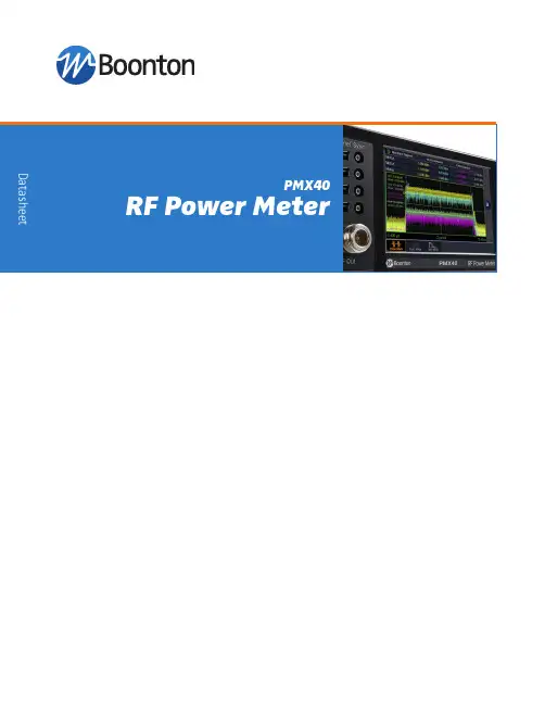
The PMX40 provides design engineers and technicians the utility of traditional benchtop instrument, the flexibility and performance of modern USB RF power sensors, and the simplicity of a multi-touch display built with Boonton award-winning technology.As a benchtop meter, the PMX40 provides a standalone solution for capturing, displaying, and analyzing peak and average RF power in both the time and statistical domains through an intuitive, multi-touch touchscreen display.The PMX40 Power Meter utilizes up to four RTP and CPS families of USB RF power sensors with industry- leading performance and capabilities either independently or for synchronized multi-channel measurements of CW, modulated, and pulsed signals.Providing the ultimate flexibility, the PMX40 sensors can be disconnected and independently used as standalone instruments.Key Features• Capture/display/analyze peak and average power• Frequency range from 4 kHz to 40 GHz• Industry-leading video bandwidth (195 MHz) and rise time (3 ns)• Industry-leading 100,000 measurements per second• Industry-leading 100 ps time resolution• Synchronous multi-channel measurements (up to 4 channels)• Sensors can be used as standalone instruments PMX40 RF Power MeterPulsed ModeAnalysis of fast-rising single pulses or pulses with short pulserepetition intervals (PRIs) requires an instrument with sophisticated trigger and data acquisition capability. Within Pulsed Mode, more than 16 pulse parameters can be measured.Continuous ModeFor simple, intuitive measurements of repetitive waveforms, the PMX40 Continuous Mode of operation provides a numeric display of average, maximum and minimum signal powers.Statistical ModeIn Statistical Mode, the PMX40 plots the Complementary Cumulative Distribution Function (CCDF). The CCDF plot shows the rate of occurrence of a specific crest factor for signals, such as those used in 5G, 4G/LTE, and Wi-Fi applications.PMX40 RF Power Meter – Front PanelConnect up to 4 USB sensors for multi-channel measurements.Multi-touch display with intuitive user interface.One touch to quickly access presets and favorite functions.Sync ports to source or receive triggers for timing and synchronization.Test source to verify sensor operation.The PMX40’s intuitive, multi-touch display enables fast configuration of up to four sensors as well as easy access to measurement and analysis tools, providing a standalone solution for capturing, displaying, and analyzing peak and average RF power in both the time and statistical domains. The meter also incorporates a test source to verify sensor operation.High-Performance and Versatile USB Power Sensors• Real-Time Power Processing™ technology with virtually zero measurement latency • 100,000 measurements per second • 80 dB dynamic range• Synchronized multi-channel measurementsAll RTP Real-Time Power SensorsThe Boonton PMX40 Power Meter utilizes Boonton RTP and CPS families of USB RF power sensors with indus-try leading performance and capabilities. All RTP sensors incorporate the unique Boonton Real-Time Power Processing™ technology, which virtually eliminates gaps in measurement suffered by other power sensors and enables industry best measurement speeds. In terms of RF performance, the RTP5000 series Real-Time Peak Power Sensors are the fastest responding sensors with 3 ns rise times and 195 MHz of video bandwidth. The RTP4000 series Real-Time True Average Power Sensors enable the lowest frequency measurements for diode-based average power measuring sensors and can make accurate measurements virtually independent of signal modulation bandwidth. CPS sensors offer flexible connectivity and performance leadership at anexcellent price point.Real-Time Power Processing™Boonton Real-Time Power Processing 1 dramatically reduces the total cycle time for acquiring and processing power measurement samples. By combining a dedicated acquisition engine, hardware trigger, integrated sample buffer, and a real-time optimized parallel processing architecture, Real-Time Power Processing™ performs most of the sweep processing steps simultaneously, beginning immediately after the trigger instead of waiting for the end of the acquisition cycle.The advantages of the Real-Time Power Processing technique are that key processing steps take place in parallel and keep pace with the signal acquisition. With no added computational overhead to prolong the sweep cycle, the sample buffer cannot overflow. As a result, there is no need to halt acquisition for trace processing. This means gap-free signal acquisition virtually guarantees that intermittent signal phenomena such as transients or dropouts will be reliably captured and analyzed.1RTPP is available within the RTP500 and RTP4000 sensors.Software FeaturesMeasurement Buffer ModeThe RTP series Measurement Buffer Mode is a remote control function that works in conjunction with Real-Time Power Processing to provide only therelevant burst or pulse information, eliminating the need to download and post-process large sample buffers. As a result, users can collect and analyze measurements from a virtually unlimited number of consecutive pulses or events without gaps. A wide variety of parameters can be calculated and plotted, such as duty cycle, pulse repetition rate, pulse width variation, and pulse jitter. In addition, anomalies,such as dropouts, can be identified.Dropouts, such as those shown left, are the sorts of events often missed by conventional power meters due to the acquisition gaps while processing takes place.Example seven pulse waveform.Measurement buffer data returned for waveform in above.Wi-Fi and Wireless Communication Signal AnalysisCharacterization and compliance testing of Wi-Fi and LTE chipsets and devices involves significant challenges for design and test engineers. With multiple-input, multiple-output (MIMO) architectures and channel bandwidths up to 160 MHz, testing is complex, especially when measuring RF power per channel and time alignment between channels. The PMX40 enables packet power measurements to be performed independently on multiple synchronous or asynchronous transmit chains with a common timebase shared among sensors.Use markers to define a portion of the waveform on which to make measurements. “Between Marker” measurements are ideal for monitoring specific portions of a packet over long intervals.Video bandwidth (VBW) describes the ability of a power sensor to track peak (envelope) power. Insufficient VBW will result in errant envelope and average power measurements. The PMX40 offers the widest video bandwidth (195 MHz) making it ideal for measuring 80 MHz, 100 MHz, and 160MHz channels.By comparing the peak-to-average power ratio, or crest factor (CF), of input and output signals of an RF transmission chain, engineers can assess circuit linearity. Additional insight can be provided with the PMX40 statistical mode Complementary Cumulative Distribution Function (CCDF) plot displaying the rate of occurrence of a specific CF. As an amplifier output compresses, the CF will reduce and the CCDF plot will move left.Indication of amplifier output compressionCrest FactorSecondary Surveillance Radar (SSR)Design, verification, troubleshooting and maintenance of secondary surveillanceradar (e.g. IFF-based radar) has never been more demanding.Proper design and operation of SSR systems is critical to the safety and security of aviation. The PMX40 can b e u sed t o easily a nd accurately capture SSR waveforms. Markers enable measurements on specific portions of the waveform.Industry-leading rise time (<3 ns) enables characterization of the most demanding radar signals.Utilize the superior 100 ps time resolution to zoom and uncover signal characteristics that might otherwise be missed.Key Features and Functionality• Data displayed as numerical meter or waveform trace • Statistical analysis with CCDF plot• Multiple marker measurements, including between marker data and marker ratios • Automated measurements; e.g., 16 automated pulse measurements • Export measurement data in .csv or .pdf formats • Up to 8 simultaneous power measurement channels• Simulation mode available to preview functionality when a sensor is not availableKey Features and Functionality• Large numeric readout and/or analog meter display • Zoom and pan through data logging strip chart• Quickly set frequency, aperture (averaging) and offset values all from the main screen• Calculates ratios between sensor measurements • Control up to 8 sensors at once• Simulation mode available to preview functionality when a sensor is not availableSensor SoftwarePower Viewer – Simple and Intuitive Measurement Software(for standalone operation of the CPS2000 Series of sensors)Power Viewer is a complimentary PC-based software package for CPS2008 sensor control, measurement configuration, and analysis. It includes USB drivers, remote control API, firmware updater and virtual instrument application.(for standalone operation of the RTP4000 and RTP5000 series of sensors)Power Analyzer is a complimentary PC-Based software package for RTP5000 and RTP4000 sensor control, measurement configuration, and advanced analysis. It includes USB drivers, remote control API, firmwareupdater and virtual instrument application.Power Analyzer - Advanced Measurement and Analysis SoftwareSensor SpecificationsRTP5006RTP5318 RF Frequency Range50 MHz to 6 GHz50 MHz to 18 GHz Dynamic RangeSpecificationsChannels Up to 4 Sensors RTP5000 SeriesRTP4000 SeriesCPS2000 Series Display5-inch WVGA multi-touch display with intuitive graphical user interfaceDisplay Modes Trace (power vs time)Statistical measurements Meter (numeric display)CCDFAutomatic measurements (pulse, statistical, and markers measurements)Marker Measurements (in Trace View)Markers (vertical cursors)Marker IndependentlyInterval Between MarkersPair of MarkersSettable in time relative to the trigger positionAvg, Min and Max Power at a specified time offsetAvg, Min and Max Power over the defined intervalRatio of power values at each markerPulse Mode – Automatic Measurements Pulse rise-timePulse widthPulse periodPulse duty cyclePulse peakPulse overshootTop level powerEdge delayPulse fall-timePulse off-timePulse repetition frequencyWaveform averagePulse averagePulse droopBottom level powerPulse edge skew between channelsStatistical Mode –Automatic Measurements Peak powerMinimum powerDynamic rangeCrest factor at cursorAverage powerPeak to average ratioPercent at cursorCrest factor at various percentsTrigger Synchronization*ModeSourceInternal Level RangeExternal Level RangeSlopeHold-off, Min Pulse Width, Max Trigger RateAmong RTP Series(internal trig distribution)Normal, Auto, Auto Pk-to-Pk, Free Run Any connected RTP Series sensor (via SMB’s) or rearpanel external trigger -40 dBm to +20 dBm (sensor dependent)±5 volts or TTL+ or -Sensor and timebase dependentTime Base Time Base Resolution, Range, AccuracyTime Base DisplayTrigger Delay RangeTrigger Delay ResolutionSensor dependent Sweeping or Roll Mode Sensor dependent0.02 divisionsSpecifications, ContinuedInputs/Outputs (front panel)USB with SMB trigger port Test Source50 MHz(optional rear panel placement)Inputs/Outputs (rear panel)LANUSB with SMB trigger portWireless Telecom Group Inc. 25 Eastmans Rd Parsippany, NJ United StatesTel: +1 973 386 9696 Fax: +1 973 386 9191 © Copyright 2020 All rights reserved.B/PMX40/0520/ENNote: Specifications, terms and conditions are subject to change without prior notice.PMX40RF Power Meter (includes 2 active channels)OptionsPMX40-4CH PMX40-GPIB PMX40-RTSAdds 2 Active Channels (for a total of 4)GPIB Control (internally installed)Moves Test Source output to the rear panelIncluded AccessoriesInformation Card (provides information on where to download the latest manual, software, utilities)Optional AccessoriesPMX40-RMK PMX40-TCASEFull-width 19” Rack Mount Kit (includes handles & hardware for mounting one or two meters)Transit case, hold the PMX40 and up to 4 sensorsRF Power SensorsCPS2008RTP4006RTP4106RTP4018*RTP4040*RTP5006RTP5318RTP5518RTP5340RTP5540True Average Connected Power Sensor Real-Time True Average Power Sensor Real-Time True Average Power Sensor Real-Time True Average Power Sensor Real-Time True Average Power Sensor Real-Time Peak Power Sensor Real-Time Peak Power Sensor Real-Time Peak Power Sensor Real-Time Peak Power Sensor Real-Time Peak Power Sensor50 MHz to 8 GHz 10 MHz to 6 GHz 4 kHz to 6 GHz 10 MHz to 18 GHz 10 MHz to 40 GHz 50 MHz to 6 GHz 50 MHz to 18 GHz 50 MHz to 18 GHz 50 MHz to 40 GHz 50 MHz to 40 GHzIncluded AccessoriesInformation Card (provides information on where to download the latest manual, software, utilities)0.9 m BNC (m) to SMB (m) cable (RTP sensors)0.9 m SMB (m) to SMB (m) cable (RTP sensors)1.8 m USB A (m) to USB B (m) locking SeaLATCH cable (RTP sensors)1.6 m USB A (m) to USB B (m) cable (CPS sensors)Ordering Information*RTP4018 and RTP4040 are currently in development. Specifications and performance subject to change。
功能参数简表vF0基本功能
0.OOHz一最大频率
0.01Hz
0.∞Hz
⅛
34H
F2-07
AI2最大输入
0.∞V-10.00V
0.01V
10.OOV
*
35H
F2-08
AI2最大输入对应设定频率
O.OOHz~最大频率
0.01Hz
50.00Hz
*
36H
F2-09
AI2输入谑波时间
0.00s~5.00s
0.01s
F4-11
设定运行时间
0h-65535h
1h
Oh
⅛
62H
F4-12
运行时间到达动作选择
0:继续运行
1:停机
1
1
★
63H
F4-13
频率检测值(FDT电
平)
O.OOHz~最大频率
0.01Hz
50.00Hz
A
64H
F4-14
频率检测FDT滞后值
O.O%~1OO.O%(FDTEII
0.1%
5.0%
*
65H
F4-15
多段速度5
0~最大频率
0.01Hz
20.00Hz
⅛
6EH
F5-06
多段速度6
0~最大频率
0.01Hz
25.00Hz
⅛
6FH
F5-07
多段速度7
0~最大频率
0.01Hz
28.00Hz
⅛
70H
F5-08
多段速度8
0~最大频率
1:启动时运行
1
1
⅛
2BH
F1-17
F1-18
保留
GSK980T参数说明书
参数一览表模拟主轴主轴为变频器控制或受模拟量控制时为“1”手轮“1”为手轮方式;“0”为单步方式半径编程X轴半径编程设为“1”标准设定:00000001RS232:通讯口设为“1”时RS232口通讯有效刀补C(选配功能):“0”无刀补C功能,“1”有刀补C功能标准设置:11001000刀补方式“0”以刀具移动方式执行刀补;“1”以坐标偏移方式执行刀补螺补(选配功能)“0”无螺补功能,“1”有螺补功能标准设定:01000100ABOT 1:绝对坐标断电不记忆0:绝对坐标断电记忆PDRN 1:空运行时。
快速运动指令运行有效(在返回参考点以前)0:空运行时,快速运动指令运行无效DECI 1:在返回参考点时减速信号为“1”表示减速0:在返回参考点时减速信号为“0”表示减速ORC 1:偏置值以半径表示0:偏置值以直径表示TOC 1:偏移矢量在复位时保持不变0:偏移矢量在复位时被清零DCS 1:按MDI面板上OUT键就直接使当前程序段运行。
(仅MDI方式)0:按循环起动信号时启动(仅MDI方式)PROD 1:在位置显示器上的相对坐标为编程位置0:在位置显示器上的相对位置含有刀具偏置后的位置SCW 1:最小指令增量按英制系统(机床是英制系统)0:最小指令增量按公制系统(机床是公制系统)标准设定:11000000SMA 1:S代码时主轴手动换挡0:S代码时主轴自动换挡M30 1:M30执行时,光标立刻回开头(B型)0:M30执行后,再次循环起动时光标返回开头(A型)EDTB 1:编辑插入机能A0:编辑插入机能BDRDY 1:驱动器/伺服准备好信号为1时准备好0:驱动器/伺服准备好信号为0时准备好PPD 1:用绝对编程零点(G50)也设置相对坐标值0:用绝对编程零点(G50)不设置相对坐标值PCMD 1:输出波形是脉冲0:输出波形是方波标准设定:00010001CM98 0:编入系统标准以外的M,S,T代码时,系统将产生相应的报警1:编入系统标准以外的M、S、T代码时,系统不产生报警,而会自动调用一个相应的子程序1.1 M代码,当系统执行标准以外的M代码时,调用的子程序为M○○M○○:调用子程序90○○1.2 S代码,当系统执行S10~S99时,调用的子程序为S□□S□□:调用子程序91□□注:当选择主轴模拟电压输出时,S代码不调用子程序1.3 T代码,当系统执行T10~T99时,调用的子程序为:T△△:调用子程序92△△注1:当执行非标准的M、S、T时,必须输入相应的子程序,否则会产生078号报警注2:非标准的M、S、T代码不能在MDI方式下运行,否则会产生M/S或T代码的报警注3:在对应的子程序中即可以编入轴运动指令,也可以对输出点进行控制(关和开),也可以根据DI的信号进行转跳或进行循环,或某一DI信号作为M/S/T的结束信号,OVRI 0:否则,进给倍率开关不对ZMX、ZMZ 当接通电源时,X轴、Z轴的参考点返回方向和原始的方向间隙方向0:返回参考点方向及间隙方向为负1:返回参考点方向及间隙方向为正注:电源接通后,当该轴向与本参数设定的反方向运动时,最初完成反向间隙补偿标准设定:00000000SMZ 0:程序段拐角处的速度控制1:所有含运动指令的程序段速度减速到零后,才执行下个程序段ZCX、ZCX 0:返回机械零点需要减速开关及零位信号1:磁开关回零方式C(在所有机械零点时有效如果机床零点在轴“正”端(从负方向向正向回零)时,需设置参数P006ZMZ~ZMX为负向回零方式。
纳普电参数测试仪PM9800说明书
PM9800使用说明书东莞纳普电子科技有限公司Ver1.7PM9800电参数测量仪(基础型)目录前言 (2)提醒与警告 (3)第1章概述 (4)1.1简述 (4)1.2主要技术指标 (4)1.3面板结构 (7)第2章操作说明 (9)第3章检定与校准 (11)第4章使用注意事项与故障排除方法 (12)第5章更多产品介绍 (13)PM9800电参数测量仪(基础型)前言感谢您购买并使用本公司的产品!本手册是关于仪器的功能、设置、接线方式、操作方法、故障时的处理方法等的说明书。
在操作之前请仔细阅读本手册,正确使用。
在使用本仪器前请首先对照装箱单对产品及附件进行确认,若有不符,请与本公司或销售商联系。
注意本手册内容因版本升级或功能升级等而有修改时,产品性能、内部结构、包装等进行修改时而不作另行说明。
关于本书内容,我们确认正确无误,但是一旦您发现有不妥或错误时,请与我们取得联系。
版本Ver1.7PM9800电参数测量仪(基础型)提醒与警告提醒为了您能安全的使用本仪器,操作时请务必遵守下述安全注意事项。
如果用本手册上所述的其它方法操作仪器,有时会损坏本仪器提供的保护。
如果是因为违反这些注意事项而产生的故障,我公司不承担责任。
警告电源与接地保护为了保证操作人员的人身安全,在将电源线接到仪器前,应检查使用场合的电源相位、零线、保护地线是否正确连接,保护地线应可靠的与大地连接,以防机壳带静电。
(注:塑料机壳无接地线)在接通本仪器的电源之前,请务必先确认仪器的电源电压是否与供给电源的电压一致。
不要在带电的情况下插拔接线端子,防止对人体造成伤害以及保护仪器不必要的损坏。
不允许连续不停的开关仪器,以免引起程序紊乱从而造成校正数据丢失而无法正常测量。
仪器外壳如不是本公司维修技术人员,请不要打开我们仪器的外壳,本仪器内,有些部分是高压,危及生命。
PM9800电参数测量仪(基础型)第1章概述1.1简述PM9800电参数测量仪是本公司最新研制的高性价比的测量仪器,能测量出电压V、电流A、功率W、功率因数PF、频率Hz等参数。
纳普 PM9200说明书
PM9200高精度功率计
PM9200的设计采用了先进的32位高速处理器和双路24位AD转换器,具有高精度,宽动态范围,结构紧凑灵巧等特点,是新一代数字新型功率分析仪。随着新能效标准的不断推出,都围绕着如何提高节能性能展开激烈的竞争,PM9200是众多企业评估设备节能性能的功率测量仪器,具有高精度,超低待机功耗测量等特点,同时RS232/485,USB,以太网等接口基本满足用户不同的测试通信需求。
0.0001mW
功率因数
0.01~1
0.5 Hz ≤ f≤ 66 Hz ±0.01
66 Hz < f ≤ 1 kHz ±0.02
0.001
频率
0.5Hz~1KHz
0.1%
0.001Hz
电能累计
0~999999MWh
0~-99999MWh
DC ±(读数的0.1% +量程的0.2% )
0.5 Hz ≤ f< 45 Hz ±(读数的0.3% +量程的0.2% )
45 Hz ≤ f ≤ 66 Hz ±(读数的0.05% +量程的0.1% )
66 Hz < f ≤ 1 kHz ±(读数的0.1% +量程的0.2% )
0.0001mAh
电能计时
99999h
± 2秒/小时
1秒
谐波
1~50次
精度等级:
B级IEC61000-4-7
基波频率最高分析次数
10Hz~65Hz 50
测量精度(0.15%)
参数
测量范围
误差
分辨率
电压
(0.5~600)V
DC ±(读数的0.1%量程的0.2% )
0.5 Hz ≤ f< 45 Hz ±(读数的0.1% +量程的0.2% )