曼瑞德混水中心用户手册+控制器调整说明
软化水设备自动控制器操作流程说明详解
软化水设备自动控制器操作流程说明详解软化水设备经过出水管上的传感流量计随机搜集输出水量信息并及时输入电脑,经贮存、运算后,发出指令给多路通伺服阀或电磁阀停止相应的操作。
同时,又把相关信息同步反应回微电脑.系统需求再生时,电脑控制电磁阀切断出水管通路,预置程序的定时启动,使反洗-吸盐-正洗-注水等工艺精确无误的停止操作。
微电脑可依据用户的需求停止优化预置。
软化水设备周期设定出水量、剩余水量、单位小时水流量、周期耗盐量、每次再生的时辰和当前工作的形式。
满足运转中的不同需求,任何时分都能够将全自动软水器运作切换为人工手动再生,以满足软化水设备运转工况的不同请求。
软化水设备应用甚为普遍,适用范围包括微粒过滤、锰砂过滤、吸收有机物、脱除余氯、软化水和除盐等设备,可为各类工业和住宅居室的各种水处置设备提供最理想的自动控制安装。
软化水设备是由全自动软水控制器(美国FLECK富莱克、AUTOTROL阿图祖控制器)、树脂罐(一般为玻璃钢树脂罐和不锈钢树脂罐)、强酸型钠离子阳树脂、盐箱组成整机。
同时我公司提供维修全自动软水器的技术支持,齐全的全自动软水器配件供应。
全自动软化水设备具有体积小、操作简单、自动运行无须人工操作等特点,已广泛应用于工业锅炉、冷却循环水、炼钢、轧钢、大型变压器、民用热水锅炉等场合。
,黑河软化水控制阀,,黑河软化水控制阀价格1、锅炉软化水设备的定义:锅炉软化水设备是针对锅炉长垢而推出的一种原水预处理装置,去处原水中的钙、镁离子以及导致锅炉长垢的原素。
2、锅炉软化水设备工作原理:由于水的硬度主要由钙、镁形成及表示,故一般采用阳离子交换树脂(软水器),将水中的Ca2 、Mg2 (形成水垢的主要成份)置换出来,随着树脂内Ca2 、Mg2 的增加,树脂去除Ca2 、Mg2 的效能逐渐降低。
当树脂吸收一定量的钙镁离子之后,就必须进行再生,再生过程就是用盐箱中的食盐水冲洗树脂层,把树脂上的硬度离子在置换出来,随再生废液排出罐外,树脂就又恢复了软化交换功能。
pH ORP控制器 使用说明书
第三章 技术参数
显示 外形尺寸 开孔尺寸 测量变量
测量范围
测量精度 输入阻抗
温度补偿
变送输出 通信输出 报警功能 相对湿度 工作温度 供电电源
贮存条件
表1 2.8 英寸单色液晶显示屏,分辨率 128*64 100mm×100mm×150mm 92.5mm×92.5mm pH/ORP pH:(0.00 ~ 14.00)pH ORP:(-1000 ~+1000)mV
VII
第一章 产品概述
第一章 产品概述
本产品是自主研发的用于在线监测 pH/ORP 值的仪表,通过 RS485 或电流变送输出到监控室进行记录保存。
pH/ORP 控制器是一款智能在线化学分析仪器,广泛应用于火电、 化工化肥、冶金、环保、制药、生化、食品和自来水等行业,对溶液中 pH 值或 ORP 值和温度连续监测。连续监测数据通过变送输出连接记录 仪实现远传监控与记录,也可以连接 RS485 接口通过 Modbus-RTU 协议 与计算机通讯,从而实现计算机对仪表监控与记录。
4.1 仪表安装.............................................................................................4 4.2 仪表接线.............................................................................................7 第五章 按键操作...........................................................................................10 第六章 仪表界面与操作...............................................................................11 6.1 监控界面...........................................................................................11 6.2 密码验证界面...................................................................................11 6.3 主菜单界面.......................................................................................12 第七章 组态设置...........................................................................................13 7.1 系统设置界面.................................................................................. 13 7.2 信号设置界面.................................................................................. 13 7.3 在线标定界面.................................................................................. 14 7.4 远传设置界面.................................................................................. 14 7.5 报警设置界面.................................................................................. 15 7.6 信息查询界面.................................................................................. 15 第八章 通讯协议...........................................................................................16
LMR PLUS 电动消防水泵控制器 FD40 说明书

Membrane KeypadDoor MountThe membrane keypad is accessible from thefront door of the controller.NEMA RatingThe standard membrane keypad is rated forNEMA 2, 3R, 4, 4X and 12.Alarm & Status LED’sA total of 20, ( 10 Status - 10 Alarm ) LED’sprovide indication on the membrane keypad. Product DescriptionThe FD40 LMR Plus Controllers are a fullservice, part winding reduced voltage controller.A part winding fire pump controller reduces thestarting current by up to 40% while maintainingup to 50% motor starting torque. The FD40 isthe most economical method of reducedvoltage starting, however, requires a specialmotor wound for part winding starting. TheFD40 can be programmed for either fullyautomatic or semi-automatic operations.The use of an embedded web page forretrieving diagnostics and history reports, alongwith USB and Ethernet communication ports fordownloading data, make the LMR Plus Series ofcontrollers easy to troubleshoot and maintain.As well, critical information can be easilyaccessed and used for report generation andanalysis, which aids in providing effective,reliable fire protection.Alarm LED’sStatus LED’sPhase ReversalPhase FailureFail To StartUndervoltageOvervoltageLow Room TemperatureLocked Rotor TripLow Suction PressureSource 2 DisconnectedProgrammable LED # 2Power OnPump RunningLocal StartRemote StartDeluge ValveEmergency StartInterlock OnLow PressureAuto Shutdown EnabledProgrammable LED # 1Power I/O BoardTransformersIncoming line voltage is run directly to the I/Oboard from the incoming lines. The I/O boardwill accept voltage inputs between 100 and600V.Silence ButtonA silence pushbutton on the membrane can beused to silence the buzzer. When an alarmcondition exists, the alarm buzzer will sound. Ifthe Silence Alarm button is pressed, the alarmbuzzer will turn off. If a subsequent alarmcondition occurs after the silence button ispressed, the buzzer will re-sound. Pressing theSilence Alarm button again, will silence thebuzzer.Motor Test ButtonThe motor test button on the membrane can beused to simulate an automatic start.Automatic Shutdown EnabledWhen the Automatic Shutdown function isenabled, a Green LED will indicate on thecontroller membrane.USB External DriveGeneralWhen using an external USB Drive, the driveshould conform to the following specifications:Min: 128mbMax: 2 Gig FAT16 protocolUSB 1.0 or 2.0Standards & CertificationNEMA 2 EnclosuresAll LMR controllers come standard with NEMA 2enclosures unless otherwise ordered. Availableoptions include: NEMA 3R, 4, 4X, 12.Emergency Start OperatorA mechanically operatedemergency start handleactivates the motorcontactor independent ofany electrical controlcircuits or pressureswitch input.Product FeaturesLogic Controller BoardCommunicationThe controller can be ordered with the option todisplay and output current values and status, oncommand, from various software protocolsthrough the appropriate port(s).Embedded Web PageThe web page is a multifunction tool that allowsthe user to view the controller’s current status,data values, programmed set points and history.It is accessed using the optional ethernet port.Ethernet PortAn optional Ethernet port can be used for directconnection to a computer for data transfer.RS485 Serial PortAn optional RS485 serial port can be providedfor communication to various external softwareprograms.USB Port / USB DriveThe logic controller board is equipped with aUSB port that can be used to transfer data toand from a portable USB Drive device (memorystick).BuzzerA buzzer is mounted on the logic board whichwill operate if Fail to Start, HardwareMalfunction or any Common Alarm conditionexists.Customer Connection TerminalsConnection terminals for external customerconnections, are located at the top of the PowerI/O board.Output RelaysFive, 8 Amp, 2 Form - C (DPDT) output relaysare provided standard on each power I/O board.They are designated for: Common Alarm,Phase Failure, Phase Reversal, Pump Run andFuture #1. Each socket has an LED mounted onthe I/O board which indicates each relay’s coilstatus.Optional Output Relay BoardsThere is provision to add up to eight additionalrelay outputs, via optional relay output boards.Each board contains a maximum of 2 additionalrelays. The Power I/O Board will accept amaximum of 4 optional boards which mount in asnap-on configuration.Each board provides an area for the user tolabel the terminal number and relay name.Drain Valve SolenoidAll LMR Plus electric controllers are equippedwith a drain valve solenoid used for weekly testpurposes.N. Y. C.APPROVEDThe LMR Plus Electric Fire Pump Controllersmeet or exceed the requirements ofUnderwriters Laboratories, UnderwritersLaboratories Canada, Factory Mutual, theCanadian Standards Association, New York Citybuilding code, CE mark and U.B.C / C.B.C.Seismic requirements, and are built to NFPA 20standards.Product FeaturesMain DisplayGeneralThe main display will show the current system pressure, time and date, voltage and amps reading for all three phases, the system frequency and any custom messages, alarmsor timers.Programmed Set-PointThe set-point display will show programmed pressure start point, pressure stop point and weekly test timer setting.StatisticsThe statistics display will allow the user to scroll through all of the measured statistics stored in memory. Refer to LMR Plus operation manual IM05805020K for specific details. DiagnosticsThe diagnostics display allows the user to scroll through various diagnostic points to assist with troubleshooting the system. Message HistoryThe user will be able to scroll through all of the messages stored in the memory of the controller with the most recent message being displayed first.PRINT MenuDescriptionAll fault and alarm information is sent to the USB and optional printer on demand, as well as the status of each output. The LMR Plus will store up to 10K events which are time and date stamped. All information can also be retrieved and displayed on the LCD display.Saving to USB DriveThe controller will save four separate text files, one CSV file and the embedded webpage to the USB external drive. The files, at maximum size, can be saved multiple times on one 128MB USB drive.Files to be saved are: Status Report, Diagnostics Report, Statistics Report, Configuration File and Last 10K Messages. Print MenuThe optional printer menu is accessed in order to select the desired print function.Functions include: Print Messages, Last XX Messages, Date & Time, Status Report, Diagnostics Report and Statistics Report. Custom MessagesWhen this item is selected, custom messages can be cleared from memory or downloaded from the USB external drive. Embedded Web PageGeneralThe embedded web page is a multifunction tool that will allow the user to view the current status of the controller as well as display all current readings, set points,and history. An externalcomputer can beconnected via theoptional Ethernetport to access thepage. Whenconnected, thecontroller setpoints can beprogrammedvia the webpage.Multiple PagesThere are 5 viewable pages that show the Main Display, Statistics, Diagnostics, History and Programmed Set Points.Pressure PointsThe pressure reports recorded in memory can be graphed and/or sorted based on date and time.Programmed Set PointsAll of the programmed set points and their current status can be viewed via the webpage. Custom MessagesTrigger PointsThe message can be programmed to appear at specific trigger points such as specific date and time, specific number of operations, specific number of hours run or at any individual alarm point.All of the trigger points can be selected asAnd/Or values.Users can create custom messages on a computer and upload to the controller using a USB Drive (memory stick). Up to 10 custom messages of up to 100 characters each, will continuously scroll across the fourth line of the LCD display once triggered.Firmware UpdateFirmware revisions are updated from an external USB drive. All previously programmed settings will remain intact when updating is completed. Should there be an update failure, the controller will automatically revert back tothe previous version of firmware. Programming MenuGeneralThe LMR Plus programming menu is divided into 8 different sub-menus. Each sub-menu contains information relative to it’s particular function. Following is a brief description of each nguageThe language sub-menu allows the user to select English, French, Spanish or Other languages to be viewed on the LCD Display. Several other languages can be uploaded into the controller. Contact the factory for details.RegionalRegional settings include the ability to program the date by adjusting the Month, Day, Year and Day of Week. As well, the Current Time can be adjusted on the 24 hour clock.PressureA variety of pressure settings can be programmed in the pressure sub-menu. These settings include disabling the pressure transmitter; setting of the start point, stop point, low pressure alarm, high pressure alarm, stop mode, proof pressure switch (for foam units), low suction shutdown (low foam shutdown), pressure deviation and hourly pressure recording. Refer to the LMR Plus operation manual IM05805020K for details.TimersTimers in the LMR Plus that can be programmed include: Run Period Timer (RPT), RPT Start Mode, Acceleration Timer (AT), Weekly Test Timer, Fail to Start Timer (FST) and Sequential Start Timer (SST). Refer to the LMR Plus operation manual IM05805020K for details. Alarm Set PointsThere are five settable alarm points that can be programmed by the user. They include: Phase Rotation, Over Voltage (OV), Under Voltage (UV), Over Frequency (OF) and Under Frequency (UF). Refer to the LMR Plus operation manual IM05805020K for details.Custom Inputs / OutputsThere is provision on the Power I/O Board to accept up to 9 additional inputs and 9 additional outputs. Each of the inputs can be labeled using m conditions.All optional inputs, outputs and LED’s can be linked, as required.Inputs can be programmed to energize the common alarm output, link to relays and optional LED’s and latch until reset by the user.Outputs can be programmed for fail safe and latch until reset by the user.Optional inputs and outputs can be programmed with time delay functions.one of 11 pre-set input descriptions or assigned a custom description that is programmed by the user. The optional outputs can be programmed to indicate up to 25 output conditions. As well, two optional alarm LED’s can be programmed for up to 12 alarSystem Configuration MenuThe system configuration menu section is password protected and contains settings such as system voltage, frequency, CT ratio etc. Refer to Technical Bulletin PU05805035K/Dfor details.Main Menu PasswordA password can be programmed by the user to protect access to the Main Menu. Refer to the LMR Plus Operation Manual IM05805020K for details.。
Watson-Marlow 520Di Pump 说明书

操作面板说明:Up :向上Start :启动:换档Stop :停止:确认Down :向下各键功能Start :启动。
泵开始运行。
Stop :停止。
泵运行停止。
Up :向上。
用于菜单选择—使光标上移一个选项。
在储存分装程序时,可通过它来依次显示“9-0”,空格和“Z-A”字符。
Down:向下。
用于菜单选择—使光标下移一个选项。
在储存分装程序时,可通过它来依次显示“A-Z”,空格和“0-9”字符。
Shift :换档。
按下Shift键后,在屏幕的坐下角会显示一个箭头符号,此时数字键盘的功能为对应键的黄色字符所表示的功能。
再按一次Shift键后,箭头符号消失,数字键盘恢复数字输入功能。
Enter :确认。
SHIFT, 0 ( . ):用于输入小数点。
SHIFT, 1 (DIRECTION):在设定分装参数时,设定泵的运行方向。
SHIFT, 4 (MAX):当泵处于手动控制模式或分装开始界面时,使泵以最高速度运行以实现快速预填充或快速排空。
SHIFT, 5 (CLEAR):在数字输入时,清除输入。
SHIFT, 6 (LOAD):用于调入储存在泵中的分装程序。
SHIFT, 7 (MENU):显示主菜单。
SHIFT, 8 (CAL):校准选项。
SHIFT, 9 (INFO):显示系统信息。
1. 开机注意:务必确认电压选择开关符合当前电压后才能开机!初次开机,系统会要求选择菜单语言,520Di目前提供有5种语言的操作界面,分别为英语、法语、德语、西班牙语和意大利语。
一般选择英语,后依次显示Watson-Marlow LOGO、泵基本信息,最后显示系统主菜单。
主菜单有5个选项,分别为:Dose:分装 - 设定、储存、调用分装参数,并执行分装操作。
Calibrate:校准 - 校准流量。
Manual:手动控制 – 手动操作520Di分装泵。
Network:网络控制 – 通过RS232通讯接口来控制520Di分装泵。
恒温混水阀的使用及调试注意事项
恒温混水阀的使用及调试注意事项内容来源自网络1、调试温度时应把出水流量开到最大。
2、调节钮正旋方向是降温、逆旋方向是升温,初次调节请注意从低温方向往高温方向调节,以防烫伤。
3、调节钮低温方向听尽头是关闭热水,高温方向的尽头是关闭冷水,如果1、调试温度时应把出水流量开到最大。
2、调节钮正旋方向是降温、逆旋方向是升温,初次调节请注意从低温方向往高温方向调节,以防烫伤。
3、调节钮低温方向听尽头是关闭热水,高温方向的尽头是关闭冷水,如果热水温度不高,可以关闭冷水只用热水洗浴,但使用过后应注意高回低温区域,以免下次使用时发生烫伤。
4、如果冷、热水进水压力不一致,且没有安装单向止流阀,请注意每次使用后,将调温钮调到低温方向尽头,即关闭热水状态,最大程度防止冷热水互串。
采购前阀门选型的步骤和依据:在流体管道系统中,阀门是控制元件,其主要作用是隔离设备和管道系统、调节流量、防止回流、调节和排泄压力。
由于管道系统选择最适合的阀门显得非常重要,所以,了解阀门的特性及选择阀门的步骤和依据也变得至关重要起来。
阀门行业到目前为止,已能生产种类齐全的闸阀、截止阀、节流阀、旋塞阀、球阀、电动阀、隔膜阀、止回阀、安全阀、减压阀、蒸汽疏水阀和紧急切断阀等12大类、3000多个型号、4000多个规格的阀门产品;最高工作压力为600MPa,最大公称通径达5350mm,最高工作温度为1200℃,最低工作温度为-196℃,适用介质为水、蒸汽、油品、天然气、强腐蚀性介质(如浓硝酸、中浓度硫酸等)、易燃介质(如笨、乙烯等)、有毒介质(如硫化氢)、易爆介质及带放射性介质(金属钠、-回路纯水等)。
阀门承压件材质铸铜、铸铁、球墨铸铁、高硅铸铁、铸钢、锻钢、高、低合金钢、不锈耐酸钢、哈氏合金、因科镍尔、蒙乃尔合金、双相不锈钢、钛合金等。
并且能够生产各种电动、气动、液动阀门驱动装置。
面对如此众多的阀门品种和如此复杂的各种工况,要选择管道系统最适合安装的阀门产品,我以为,首先应了解阀门的特性;其次应掌握选择阀门的步骤和依据;再者应遵循选择阀门的原则。
C-90混水器使用说明书
特别提醒:我们在产品出厂前已经将各项技术参数调试设定完毕,如无特别需要建议您直接插电运行即可。
强烈建议您将混水系统装在有地漏,不怕水、检修方便的位置,任何水暖系统都有泄漏的可能性存在。
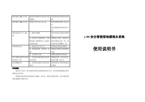
c-90安全智能型地暖混水系统使用说明书一、技术参数:1、额定电压:AC220V 50HZ;2、限温式断水保护温度:5-95℃(出厂设置40℃)3、混水控温:±1℃4、控温范围:5-95℃(出厂设置40℃)5、系统循环泵扬程:6m(最高扬程)6、最大功率:98W(水泵运行时)7、管路公称压力:PN10 8、供水温度不高于95℃9、面积200㎡以下 10系统压力低于0.5bar或高于6bar系统断电,进水阀自动关闭11、低温启动模式:水温高于20°但低于设定值5°阀门泵开,水泵呈间歇式运行(可以设置其它温度)二、混水系统安装及保养注意事项:1、混水系统各个部件结构及安装尺寸请对照所选购产品的示意图进行安装连接,进回水装反系统无法正常工作。
2、为了便于以后的维修和系统的正常运转,强烈建议用户在集中供热进水口加装过滤装置。
3、本系统安装前,应检查管路系统是否连接可靠,并确保管道中的杂质、焊渣、污垢已经清除干净:电源频率为50HZ,电压为单项220V,电压波动值应在-10%~+6%;4、系统应安装在干燥通风处,以防受潮短路或被水喷溅,且安装便于以后维修和更换;5、系统为配套供热系统工作时,切勿用手触摸电泵及其管路,以免烫伤;6、电源插头应严格接地,将插头接地脚与电源插座接地孔进行可靠连接,不得擅自改变混水接地插头;7、混水系统工作时,应在使用场地建立醒目安全警示标志,谨防发生意外事故;8、如系统出现渗漏现象维修时或有触及电泵、控制器的动作时,必须先切断电源,以防意外事故发生;四、温馨提示:传感器出现故障,温控器关闭输出,并显示相关错误代码。
E1:室温传感器短路报警;E2:室温传感器断路报警;五、安装:1.固定好支架,按照要求接上分水器。
混水系统及详细说明书
混水系统混水中心:混水换热调节系统又称为换热控制中心,由电动四通调节阀或三通调节阀、循环水泵、带温表球阀、比例积分控制器、温度传感器、过滤阀、电动调节阀、分集水器装置组成,换热中心。
输出温度35-60℃进水温度0-99℃工作原理及作用通电后,进水阀门无条件打开,热水进来,当系统检测到水温高于35度时,水泵工作。
具体如下。
例如,当用户设定温度为50度时,当进水温度低于50度时,进水阀门全部打开;当进水温度高于50度时,进水阀门自动关小,回水阀门同步打开,供回水按比例混合,自动调整为50度。
国家规定必须低于60℃,超过60℃会造成甲醛超标,地暖管寿命降低,爆管等恶劣现象,而本系统能有效解决这些问题主要应用范围及特点集中供暖+地暖锅炉+地暖散热器,地暖混装系统混水系统采用国际领先的屏蔽水泵,耗电低(最低46瓦,最高100瓦)噪音低≤45db,寿命长,可连续5000h连续工作(有水)技术参数使用面积:160㎡(常规)温控精度:±2℃流速:0.25-0.4m/s扬程:6m一次供水额定流量:1200L/h二次供水额定流量:300L/h分水器中心间距:210mm最大工作压力:0.8mpa噪音≤45db防护等级:IP44功率:46-100瓦材质:黄铜进水方向:左进水或下进水安装注意事项1.安装前,应彻底检查管路系统,是否连接可靠,并确保管道中杂质焊渣污垢已经清除干净,尤其是北方使用PPR管道焊接时,确保焊接后流量不能太小2.供回水处均需加装阀门,便于以后维护,保养,供水处必须加装过滤器,以保护水泵,条件许可下尽量采用水平进水,其次是下进水。
3供回水连接正确,不得接反。
4本系统一般应安装在干燥通风处,以防受潮短路或被水喷溅,附近最好有地漏。
5安装:配有专用支架(上下间距为220mm)1用户及调试人员在使用及调试中除温控器及塑料部位外,应严格遵守用电常识,一般不得触摸其它金属部位,以防烫伤及其它意外。
2.当用户需要调整温度时,只需按上下键即可3.电动执行器的旋钮水平时为全关,垂直(与地面)为全开4.手动操作:不通电时,按下电动执行器进行旋钮,呈垂直(与地面)状态,相当于没装该系统,这时热水应该能自然循环(这是一切工作的前提),如果不能自然循环,要检查阀门是否全部打开及是否有压差。
混床超纯水设备操作系统操作说明

混床超纯水设备操作系统操作说明离子交换设备是利用阴、阳离子交换树脂的交换吸附性能,去除水中的各种阴、阳离子,达到去离子的目的,离子交换设备按单台设备分类,可分为阴床、阳床、混床。
在水处理应用中,由阳床、阴床单组或阵列装置而成,后置混合离子交换器,能得到更高纯度的産出水,具有投资节省、工业成熟等特点。
离子交换设备是制备高纯水的必要设备,广泛应用于电子、电镀、锅炉用水等领域,与RO、EDI设备组合后水质的电阻率可达到18.2MΩ.CM.所谓混床,就是把一定比例的阳、阴离子交换树脂混合装填于同一交换装置中,对流体中的离子进行交换、脱除。
混床超纯水设备本体是带上下碟形封头的圆柱形钢结构,内壁衬5mm耐酸耐碱硬橡胶防腐;设备内部中排装置由不锈钢管、不锈钢缠绕管焊制而成;集水装置为衬胶多孔板配滤水帽。
混床超纯水设备操作系统操作说明1、正洗打开混床进水阀一、排气阀,水流自上而下,当水充满设备时打开下排阀,关闭排气阀,正洗流速同制水流速,当出水电阻率大于出水要求时,转入制水。
2、制水正洗结束,打开出水阀,关闭下排阀,稳定制水流量,直至出水电阻率小于要求时,制水周期结束。
3、再生(1)反洗预分层打开混床反洗阀、反洗排放阀,控制反洗分层流速10 m/h 左右,以树脂充分膨胀流动,且正常颗粒树脂不被水冲出为最佳控制流速,以阴阳树脂基本分层为反洗终点。
(2)沉降打开排气阀,使反洗预分层后展开的树脂自然、均匀地沉降下来,而后打开下排阀,使容器内液面降至树脂层面以上10~20cm处,避免进再生液时不必要的稀释。
(3)失效打开混床进碱阀、进水阀二、下排阀,浓度按4%左右控制,并注意当喷射器进水流量发生变化时, NaOH吸入量也会发生变化,要加以调整;进碱时间45分钟左右。
(4)反洗分层打开混床反洗阀、反洗排放阀,控制反洗分层流速10 m/h 左右,以树脂充分膨胀流动,且正常颗粒树脂不被水冲出为最佳控制流速,以阴阳树脂分层界限分明为反洗终点。