ETL-Plus-安装配置指南
ETLPLUS使用指南

ETLPLUS使⽤指南ETLPLUS使⽤指南第⼀章:ETL*PLUS简介 (2)第⼆章:功能详解和操作 (4)⾸次配置 (4)作业管理配置 (14)作业调度 (40)监控机制 (60)注意事项及常见问题 (81)第三章:运⽤上线检查的标准 (86)运⽤设计阶段 (86)集成测试阶段 (87)运⽤上线阶段 (87)⽂件信息修订记录⽂件审核/审批此⽂件需如下审核⽂档分发此⽂档将分发⾄如下个⼈或机构第⼀章ETL*PLUS简介在数据仓储 (Data Warehousing) 环境的建置过程中, ETL*PLUS机制的好坏不但在建设初期会决定数据仓储是否能够顺利进⾏, 同时也会影响到系统在后续维护上的容易性.ETL 指的是E xtraction, T ransformation 与L oading. Extraction 指的是如何将数据从来源端 (Source System) 中截取出来. Transformation 指的是在截取出来的数据格式与数据仓储所需要的数据做转换. Loading 指的是将数据加载⾄数据仓储中. 但由于在数据仓储中, 通常所牵涉的数据来源会⾮常多, 同时所须加载的数据量会相当多. 所以⼀个设计完善且容易维护的ETL*PLUS 机制对数据仓储项⽬的进⾏就显得⾮常重要了.所谓的 ETL*PLUS机制指的是在数据仓储的项⽬中, 能够让许多的作业在作业的执⾏条件满⾜时就能够⾃动地执⾏这些作业.这其中包含了可能需要接收⼀些档案来做数据加载⼯作的作业, 或者是做⼀些数据整合的作业. ⽽作业在执⾏时可能还会有⼀些条件的限制及其它种种的功能.ETL*PLUS具有全浏览器⽅式,使⽤⼗分⽅便,具有很强的跨平台性。
具有很强的作业状态监控功能;能够对企业的调度进⾏统⼀管理,这样有利企业的管理。
ETL*PLUS对后台作业采⽤的是具有很强跨平台的语⾔Perl,从⽽使作业与平台⽆关性。
这也是ETL*PLUS的强⼤之处。
ETLPLUS使用指南

ETLPLUS使用指南第一章:ETL*PLUS简介 (2)第二章:功能详解和操作 (4)首次配置 (4)作业管理配置 (14)作业调度 (40)监控机制 (60)注意事项及常见问题 (81)第三章:运用上线检查的标准 (86)运用设计阶段 (86)集成测试阶段 (87)运用上线阶段 (87)文件信息修订记录文件审核/审批此文件需如下审核文档分发此文档将分发至如下个人或机构第一章ETL*PLUS简介在数据仓储 (Data Warehousing) 环境的建置过程中, ETL*PLUS机制的好坏不但在建设初期会决定数据仓储是否能够顺利进行, 同时也会影响到系统在后续维护上的容易性.ETL 指的是E xtraction, T ransformation 与L oading. Extraction 指的是如何将数据从来源端 (Source System) 中截取出来. Transformation 指的是在截取出来的数据格式与数据仓储所需要的数据做转换. Loading 指的是将数据加载至数据仓储中. 但由于在数据仓储中, 通常所牵涉的数据来源会非常多, 同时所须加载的数据量会相当多. 所以一个设计完善且容易维护的 ETL*PLUS 机制对数据仓储项目的进行就显得非常重要了.所谓的 ETL*PLUS机制指的是在数据仓储的项目中, 能够让许多的作业在作业的执行条件满足时就能够自动地执行这些作业. 这其中包含了可能需要接收一些档案来做数据加载工作的作业, 或者是做一些数据整合的作业. 而作业在执行时可能还会有一些条件的限制及其它种种的功能.ETL*PLUS具有全浏览器方式,使用十分方便,具有很强的跨平台性。
具有很强的作业状态监控功能;能够对企业的调度进行统一管理,这样有利企业的管理。
ETL*PLUS对后台作业采用的是具有很强跨平台的语言Perl,从而使作业与平台无关性。
这也是ETL*PLUS的强大之处。
第二章:功能详解和操作首次配置第一步:在ETLPLUS中配置用户与执行系统关系(由运维组人员部署CLIENT 程序时操作)注意:该步骤在运维人员部署CLIENT程序时已经配置完成!执行系统,即为运用的名称,在ETLPLUS中被定义为执行系统以system用户登录UA统一认证平台左键单击“登录”进行UA系统选择界面,如下:左键单击选择系统中的“etlplus-zx”,进入ETLPLUS管理主界面,如下选择配置管理->系统管理,进入如下界面单击新建系统,进入如下界面输入相应的属性:系统名称:即为运用的名称系统简称:即为运用的系统简称,请使用英文大写左键单击确定接下来,选择权限管理->用户与执行系统关系,进入如下选择,需要配置的用户(即为运维人员部署程序是创建的运用用户),进入如下界面在系统列表中,选中相应的系统,单击确定,配置完成。
PLUS站安装步骤
PLUS站安装步骤一、准备工作1、电脑主机一台:硬盘容量不低于150G、双硬盘、至少三个个网口,处理器和内存最好大一些,性能强一些,具体配置请查看运行的PLUS站配置。
2、Windows Server 2003 SP1英文系统的安装光盘、制作的装系统U盘或者移动硬盘,安装系统必须是英文的,最好是纯净版本。
3、Delta V 8.4.2安装光盘4、U盘或者移动硬盘、电脑显卡、网卡、声卡、硬盘等驱动盘。
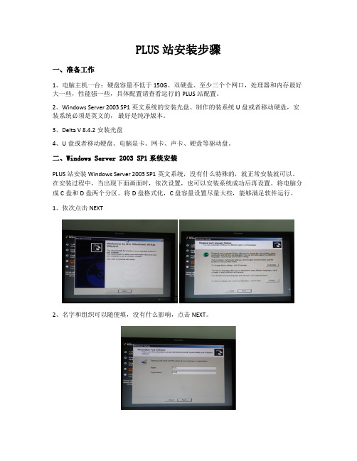
二、Windows Server 2003 SP1系统安装PLUS站安装Windows Server 2003 SP1英文系统,没有什么特殊的,就正常安装就可以。
在安装过程中,当出现下面画面时,依次设置,也可以安装系统成功后再设置。
将电脑分成C盘和D盘两个分区。
将D盘格式化,C盘容量设置尽量大些,能够满足软件运行。
1、依次点击NEXT2、名字和组织可以随便填,没有什么影响,点击NEXT。
3、点击NEXT4、密码输入deltav2008,点击NEXT。
5、时区选择北京这个选项,点击NEXT。
6、系统一直安装完成。
7、安装电脑显卡、网卡、声卡、硬盘等驱动。
三、系统安装完毕对一些功能进行设置1、系统安装完成,登陆电脑账号:administrator,密码:deltav2008。
2、右键点击桌面电脑图标选择属性,点击电脑名选项,点击CHANGE。
3、需要输入电脑名和工作组,电脑名为:ATL_PLUS,工作组为:DELTAV,填写完成,就点击OK。
4、再点击属性对话框的高级选项,点击性能(Performance)中的设置,在visual effects选项:选择调整到最佳性能(adjust for best performace)。
再选择performace\高级选项,点击change。
左键点一下C盘,在下面两个框中填上2048、4096;左键点一下D盘,在下面两个框中填上4096、4096,点击SET,再点击OK。
Kettle开源ETL平台_安装配置及使用说明v1.1

修订记录目录修订记录.................................................................................................................................... 错误!未定义书签。
1.安装与配置........................................................................................................................ 错误!未定义书签。
1.1ETL与K ETTLE概述................................................................................................. 错误!未定义书签。
1.2K ETTLE的下载与安装 .............................................................................................. 错误!未定义书签。
1.2.1Windows下安装配置Kettle ................................................................................. 错误!未定义书签。
1.2.2Linux下安装配置Kettle....................................................................................... 错误!未定义书签。
1.2.3Kettle下安装JDBC数据库驱动 ......................................................................... 错误!未定义书签。
银河麒麟服务器操作系统Oracle+数据库安装与配置指南

目录第1章 配置内核参数 (1)第2章建立ORACLE用户 (3)1.1.在超级用户下创建新的组和用户 (3)1.2.建立O RACLE软件的安装目录 (3)第3章 安装ORACLE补丁与JAVA开发包 (4)3.1安装P3006854_9204_LINUX补丁 (4)3.2安装J A V A开发包 (4)3.3软件介质 (4)第4章 安装ORACLE DATABASE (5)4.1编辑 (5)4.2启动O RACLE U NIVERSAL I NSTALLER (OUI) (5)第5章 创建数据库 (11)5.1编辑 (11)5.2切换到ROOT的终端,安装 OPATCH。
(11)5.3最后切换到ORACLE终端 (11)第6章 参数配置建议 (17)第1章 配置内核参数Oracle数据库对系统的硬件配置有基本的要求,包括机器主频、磁盘空间和内存大小,但作为服务器的机器一般是满足的,这里就不赘述了。
下面的一些参数需要根据机器系统的实际情况,特别是内存的大小来进行设置,这里假定内存为2G,页面大小为4K。
为使Oracle 数据库管理系统在运行时有更好的性能,应尽量给数据库留出较多的内存。
在以下的内核生成过程中,假设内核源码位于/root/kylin2.0,并定义为环境变量KSROOT。
# cd $KSROOT/arch/i386/conf# cp GENERIC ORACLE# cat >> ORACLEoptions SEMMAP=128options SEMMNI=128options SEMMNS=32000options SEMOPM=250options SEMMSL=250options SHMMAXPGS=65536options SHMMAX=2147479552options SHMALL=524287options SHMMNI=4096options SHMSEG=4096options MAXDSIZ="(1024*1024*1024)"options MAXSSIZ="(1024*1024*1024)"options DFLDSIZ="(1024*1024*1024)"注:根据上面的假定,Kylin页大小为4k ,这样2G的内存,其SHMALL可以为524288,这里设定524287,也是考虑到实际情况,用dmesg工具就可以看到,可用的内存实际上并没有2G,比2G稍少。
APOLLO 1550ETL 1650ETL双臂门电动驱动器安装指南说明书

APOLLO Gate Operators, Inc.INSTALLATION MANUAL04/07CONTENTSIMPORTANT SAFETY INSTRUCTIONS (3)Applications (4)Pre-Installation Checklist (5)Parts Identification (6)Operator Installation ................................................7-9Pivot Arm InstallationActuator InstallationControl Box InstallationConnecting the ActuatorGate Bracket InstallationLimit Switch AdjustmentControl Board ConnectionsControl Board Adjustments- Learn Mode1550ETL/1650ETL Actuator Option (10)Push to Open Installation (11)Programming Instructions (12)Control Board Description ..................................13-17 Siren Connection (18)Radio Receiver Options (19)Troubleshooting guide ..............................................20-22 Warranty .. (23)WARNING- To reduce the risk of injury or death:∙ READ AND FOLLOW ALL INSTRUCTIONS.∙ Installation should be performed by a professional installer.∙ Required welding should be performed by a qualified welder.∙ Should electricity be required, use a certified electrician only.∙ Any device that requires 120 Volts AC should be U.L. approved.∙ Review with the owner all safety concerns including:⇒ Do not operate the gate unless area around gate is in full view.⇒ Never let children operate or play with gate controls. Keep the remote control away from children.⇒ Always keep people and objects away from the gate. NO ONE SHOULD CROSS THE PATH OF THE MOVING GATE.⇒ Periodically test the obstruction sensitivity to assure safe and proper operation.Do not test sensitivity by standing between the gate and the hinge orstop post.⇒ The “CAUTION AUTOMATIC GATE” signs should be clearly visible from both sides of the gate.⇒ Always insure that the gate has closed securely before leaving area.⇒ Arrange with local fire and law enforcement for emergency access.∙ Use the emergency release only when the gate is not moving.∙ A secondary entrapment device such as loop detectors, edge switches, and beam detectors are highly recommended and required to meet the UL325 standard.∙ Install control devices such as keypads far enough away (5 feet or further) from any moving parts of the operator and gate to prevent possible injury.∙ Do not install control box where the gate can come in contact with person using the push button on side of control box.∙ Always disconnect the battery or power source when making adjustments or repairs to any part of the gate or operator.∙ All rollers should be covered to prevent injury.∙ KEEP GATES PROPERLY MAINTAINED. Read the owner’s manual. Have a qualified service person make repairs to gate hardware.∙ The entrance is for vehicles only. Pedestrians must use separate entrance.Test the gate operator monthly. The gate MUST reverse on contact with a rigid object or stop when an object activates the non contact sensors. After adjusting the force or limit of travel, retest the gate operator. Failure to adjust and retest the gate operator properly can increase the risk of injury or death.SAVE THESE INSTRUCTIONS.APPLICATIONSThe Apollo Model 1550ETL/1650ETL Swing Gate Operator is approved for Vehicu-lar Class I & II usage under UL 325Guidelines, and is designed to handle swing gates up to 16 feet in length and600 pounds each. A professional fence or gate dealer is recommended to assure proper installation.Apollo Gate Operators are available only through qualified dealers with an outstanding reputation in the fence and gate industry. These dealers will be able to recommend the proper equipment for particular applications.Apollo Gate Operators are 12 Volt DC (Direct Current) powered. A 12 Volt sealed battery(33 ampere hour minimum) with connecting posts located on the top is recommended. There are several advantages with 12 Volt DC systems:∙ Low voltage virtually eliminates risk of electrical shock.∙ Battery powered operators provide up to 200 operations in the event of power outages.∙ The battery may be recharged with a trickle charger or by solar energy (Electrical battery chargers should have a class 2 transformer rating).If a trickle charger is used and a standard electrical outlet is not readily available, a licensed electrician will be required for proper electrical hook up.The following table should be used as a guide for capacity of operation of operators only, additional options may reduce the the daily usage.Please note that the charge capability of solar panels will vary with different geographical locations.Daily Cycles1-101-201-401-601-8080+5 watt solar panel*10 watt solar panel*20 watt solar panel(requires 5310 regulator)*30 watt solar panel(requires 5310 regulator)*40 watt solar panel(requires 5310 regulator)*1.5 amp battery charger*10 amp battery charger*Note: Double the amount of solar panels for Dual Gate Operators.PRE-INSTALLATION CHECKLIST The following check list should be used before beginning installation:Verify that the proper operator has been selected for this application.Verify proper installation and operation of the gate.1. Are the hinges servicable?2. Does the gate swing free and level?3. Will the gate require a locking device?4. Is the hinge and stop posts sturdy enough to handle the gate & operator?5. Does the gate meet U.L. construction?Determine the general location of the operator, attachment points, and solar panel (if used).1. Is there a suitable location for the operator?2.Can the solar panel (if used) be mounted in an unobstructed area facingsouth (in the northern hemisphere)?3. Will additional solar panel cable be required?4. Is electricity available (if required)?Consider safety and access options. Recommend if needed.1. Will there be children or animals in the area?2. Are safety loops, edge switches, or photo beam detectors required?3. How can the gate be opened in emergencies?4. How will visitors enter and exit?5. Will vehicles (and trailers) have sufficient room off roadway to operate anycontrol devices such as keypads?IMPORTANTNever weld parts to the gate or posts when the operator circuit board is powered. Doing so may damage the board beyond re-pair.PARTS IDENTIFICATION#10025215Gate Bracket(2 with 1650)#1125Hardware Kit (2 with 1650)#404CAutomatic Battery Charger (optional)#2015 Watt Solar Panel & Bracket(optional)(2 required with 1650)816EActuator with 8’ cable (816EX slave actuator with38’ cable supplied with 1650)#11111BControl Box#10000415Pivot Arm(2 with 1650)#446Bolt On Pivot Arm (optional)(2 required with 1650)#273GCAUTION Signs (2 each)(4 each with 1650)OPERATOR INSTALLATIONCenter Line of attachmentpoint for gate bracketHinge post Front ViewGate (closed)13”6”Direction ofopening13”6”Top ViewControl Box InstallationMount the control box within 4 feet of the pivot arm.Do not mount the control box where the person using the push button on side of the box can come in contact with the e mounting hardware capable of supporting the weight of the control box with the battery installed.Connecting the Actuator (s)Set battery inside of control box with terminals toward the front (Do not use any battery with side terminals).Connect actuator cable to the “MASTER ”connector on the control board.If a 1650 Dual Operator is being installed and conduit is being used under the drive (recommended), cut the slave (opposite side where control box is mounted) actuator cable about 12” from the white connector. Run the remaining cable across the drive through conduit and up through the control box. Cutoff any excess cable and splice the short piece back to the cable.* Connect to the “SLAVE ”connector on the control board.Connect the RED power wire (s) to the battery positive ( + )and the BLACK power wire (s) to the battery negative (- )1/2” x 3 1/2” Hex Bolt1/2” Washer1/2” Lock NutDo not over tighten nutActuator Installation* Instead of cutting the slave cable, remove the pins on the plug with a jeweler's common blade screwdriver or appropriate tool (the staples on the actuator shipping carton work great) ,run the cable through the conduit and reinsert the pins into the plug.MASTERSLAVE1/2” x 3”Bolt1/2” Lock Nut1/2” Washer (2 places)Extend Limit Screw Retract Limit Screw IMPORTANTNever weld parts to the gate or posts when the operator circuit board is powered. Doing so may damage the board beyond repair.1550ETL / 1650ETL Actuator OptionThe Apollo1550ETL and1650ETL systems– which use the835/836boards– come standard with the816E / 816EX actuators. These actuators have a gray cable restraint and are considered our “smart” or “intelligent” actuator. These actuators utilize all of the features of the835/836 board.Please note that if a416 (non-intelligent actuator) is to be used on a1550ETL / 1650ETL system:1.Switch #10 (SMART ACT.) must be in the OFF position.2.The “slow start” / “slow stop” feature of the835/836board will not work withthe416actuators.The rest of the set-up and operation of the system is the same as with the “smart”actuators. For example, limit switches on the actuator must be set before proceeding with the current sensing procedure.Cable Length of 816E / 816EX ActuatorsIt is not recommended to lengthen or shorten the cables of these actuators– as they have a sensor in the actuator. Should special length cables be required, they are available by special order in any length up to 50 feet.If it is necessary to cut the cable, special attention should be given to ensure that proper electrical splices are performed.Should the cable of the816E / 816EX actuator need to be pulled thru conduit, it is recommended that the plug be removed, cable pulled, then the plug re-installed. (Specific instructions for this are available from your distributor or Apollo Technical Assistance.)Both measurements are taken from the center of 11”6”Gate (closed)Top ViewVertical position of Center Line of attachment point for gate bracketFront ViewMust be re-wired for proper operation8 Pin Connector (s)PROGRAMMING INSTRUCTIONSOnce the operator is installed or if the control board is replaced, you will need to program the control board for proper current sensing. The operator should be functional and the open and close limits set.1.Push and hold the LED ENABLEbutton for five seconds.The “STOP ” LED will blink indicating the board is in learn mode.2. Cycle the gate three full times (must reach the open and close limit switches on each cycle ).The “STOP ” LED will now stay illuminated.3.Adjust the current sensitivity pot to insure safe operationThe current sensitivity may be readjusted at any time without relearning the board.Periodically check the current sensitivity for safe operation.The 835/836circuit boards incorporate a safety feature that will put the operator into a hard shut-down mode if the circuit board detects a current sense two consecutive times during a cycle. This hard shutdown condition can only be reset by shorting the FIREBOX or UL connectors on the left side of the circuit board to ground. If a firebox is used in the installation, The firebox door should be opened and closed to reset the circuit board.CLOCKWISE Less sensitivity Gate is harder to current senseCOUNTER CLOCKWISE More sensitivity Gate is easy to current senseLED Enable & LearnMode Push ButtonOptional Device InputsStop Circuit JumperFire & ETL InputsEmergency BypassReverse Battery PolarityIndicatorsOptional Device InputRemote Monitor Outputsand Photo EyeGateLink ConnectorMicroprocessorTimer To Close -Dual Gate Delay -Current Sensitivity -AdjustmentsProgram Switches835/836 Control Board Parts IdentificationActuator Connector(Master)Actuator Connector(Slave)Control Board ResetHard Shutdown ResetOperate Push ButtonBoardActuatorFunctionCable Pin 1Orange Open Limit Pin 2White Close LimitPin 3Black Motor (positive on open, negative on close)Pin 4Red Motor (negative on open, positive on close)Pin 5Green Common for both limit switchesPin 6Yellow Feedback from intelligent actuator(816E/816EX)Pin 7Black Battery Negative Pin 8RedBattery Positive13572468Actuator ConnectorApplies battery voltage directly to motor to open gate if control board fails. User must unplug before gate opens to maximum travel or 15 amp fuse will open. Fuse should be checked before returning gate to service.EMERGENCY BYPASS (open only)Photo eye / safety loop wiring. Connect the positive power wire of the accessory to 12V. Connect the ground wire of the accessory to MAS (upper right area of the 835/836 board). Connect the relay wires of the accessory as normal: COM to GND.NO to SAFETY (#14) (for a safety device). When the gate operator begins opening (comes off of the closed limits) the MAS terminal will become a ground and will complete the flow of power to the accessory. This will power the accessory up and it will work as normal until the gate gets closed and the MAS terminal switches and thedevice will power down.Photo Eye HookupRemote Outputs and Photo Eye HookupAdjustmentsPush ButtonsTIMER TO CLOSE Adjusts time before gate automatically closesAdjustable 5 to 70 seconds.DUAL GATE DELAY Adjusts delay between master and slave op-eration 0-4 seconds (836 only for use withmagnetic, solenoid, and other locking devices)CURRENT SENSITIVITYIncreases or decreases the Auto Reversesensitivity.LED ENABLEWhen depressed, activates LEDs for 15minutes to assist in installation and troubleshooting.Hold the push button down for five seconds to putthe board in program mode.RESETResets the microprocessor. Returns processor tolast known state.OPERATE When depressed, activates the gate. Used for initialinstallation and testing.Hard Shutdown Reset Resets the operator when the gate currentsenses twice before fully opening or closing.JumpersSTOP CIRCUIT JUMPER When the STOP CIRCUITprogram switch #5 must be ON JUMPER is connected, the gatewill operate normally.STOP CIRCUIT JUMPER When a 3-button station is con-program switch #5 must be OFF nected to the board, the STOPCIRCUIT JUMPER must be re-moved.Program SwitchesOFF ON1 TIMER TO CLOSE Gate does not automatically close.Gate automatically closes.2 TIMER TO CLOSE OPT.Gate automatically closes from Gate automatically closes only when completelyany position after opening.open (open limit engaged).3 SLAVE DISABLE Enables slave side (dual gate use).Disables slave side. (single gate use)4 SIREN DELAY Siren (optional) active when gate is Siren (optional) starts5 seconds before gate moves.moving.5 ‘STOP’ CIRCUIT ENABLE Must hold down open or close Normal operationbuttons to move gate. Gate stops Momentary open or close input runs gate to limit.when button released.6 LOCK TYPE For 12V mechanical (solenoid) locks.For 12V magnetic locks.(+12V for 4 seconds on open cycle)(+12V when on close limit)7 COAST ENABLE Gate will stop immediately when at Gate will coast (minimally) when it reaches limits.Open or Close limit Recommended for 7500 slide operator only.8 FREE EXIT OPT. A free exit input will open gate from A free exit input will open gate from anyclosed position or after a close cycle position after an open or close cycle.only.9 DUAL GATE SYNC Both gates operate at normal This feature will control the master gate to openSpeed (slave slower than or close at the same speed as the slave gate.Master).10 SMART ACT.Off for 416E & 416EX actuators,Used for 816E & 816EX actuators onlyslide gates, 3500 or when slow down(soft start & stop).feature is not desired.Optional Device InputsGND Supplied Battery GroundINP Activate Gate (Push button activation when momentarily shorted to ground)12V Supplied Battery Voltage (Protected with 3 Amp fuse)GND Supplied Battery GroundINP Activate Gate (Push button activation when momentarily shorted to ground)12V Supplied Battery Voltage (Protected with 3 Amp fuse)EDGE Reverse edge input. When grounded, will stop and reverse gate if closing, resets close timer if gate is open.EDGE Reverse edge input. When grounded, will stop and reverse gate if closing, resets close timer if gate is open.GND Supplied Battery GroundGND Supplied Battery GroundSTOP Stop input from a 3 button station (must remove STOP CIRCUIT JUMPER) Normally closedCLOSE Close input from a 3 button station (see program switch #5 for options)OPEN Open input from a 3 button station (see program switch #5 for options)GND Supplied Battery GroundGND Supplied Battery GroundFREE EXIT Opens gate if closed, stops and reverses gate if closing, resets close timer if gate is open.GND Supplied Battery GroundSHADOW Resets close timer when gate is open (also referred to as under gate loop)GND Supplied Battery GroundSAFETY Resets close timer if gate is open, stops and reverses if gate is closing. (Does not open a closed gate) GND Supplied Battery GroundFIRE When grounded, opens gate and holds gate open until released.Clears “Hard Shutdown” mode of software.UL When grounded, opens gate and holds gate open until released.Clears “Hard Shutdown” mode of software.GND Supplied Battery GroundINP Activate Gate (Push button activation when momentarily shorted to ground)12V Supplied Battery Voltage (Protected with 3 Amp fuse)APOLLO Gate Operators, Inc.The 911 Siren is included with all Apollo ETL Gate Operators.RedBlackSet Program Switch # 4 as preferred:- Upon activation, Siren will start for 5 seconds before gate(s) begin moving.- Siren and gate(s) start immediately upon activation.APOLLOGate OperatorsRECEIVER OPTIONSDo not confuse the receiver code switches with the red program switches on the gate control board.Never set all code switches to the same position. Transmitters must match code switches for proper operation.If power is taken directly from battery or connected as shown below, receiver should be configured for 12VDCAllstarLift-Master*HeddolfLinear* Lift-Master will require that the 12/24 jumper be set to 12 and the C/M (constant/momentary) jumper be set to CTROUBLESHOOTING OPERATOR & ACCESSORIES Some troubleshooting will require a hand held multimeter. An inexpensive digital multimeter may be purchased at Radio Shack or a local electric supply company. Refer to the owners manual forinstructions.Gate opens OK but after closing, opens back up.1. Excessive closing pressure on gate. Re-adjust the close limit switch on the actuator.2. Automatic reverse sensitivity is set too sensitive. Re-adjust-CAUTION: Automatic reverse sensitivityshould be set sensitive enough to avoid injury.3. Gate is mechanically binding. Disconnect actuator from gate and eliminate binding.4. Battery voltage is too low. Battery voltage should be 12 to 14 volts under load. Check solar panel output orbattery charger output or re-evaluate usage.5. Replace circuit board.Gate moves only a few feet, then stops or reverses.1. Battery voltage is too low. Battery voltage should be 12 to 14 volts under load. Check solar panel output orbattery charger output or reevaluate usage.2. Gate is mechanically binding. Disconnect actuator from gate and eliminate binding.3. Actuator extension tube is bent. Inspect for damage and replace extension tube if required.4. Current sensitivity is adjusted too sensitive. Re-adjust current sensitivity.5.Program switch #10 is on using a non-intelligent (416E) actuator. Turn switch #10 off.5. Replace circuit board.Gate surges too much. Does not run smooth.1. Pivot arm is not ridged. Re-weld and/or brace pivot arm.2. Bolts are loose. Snug all bolts. Pivot arm bolt should be snug but not tight.3. Gate is too limber. Reinforce gate.Gate will open using push button on side of box, but not with transmitter.1. Code switches do not match. Check that the code switches in the transmitter and the receiver match.2. Low or dead battery in transmitter. Replace battery.3. Fuse blown on circuit board. Check fuses on gate control board.4. Low battery in operator. Battery voltage should be 12 to 14 volts under load.5. Replace receiver.Note:Code switches for receiver are inside of receiver. Do not confuse with program switches on control board.Transmitter works, but not very far.Note: Transmission distances will vary according to terrain, obstructions, and electrical interference. The normal range from inside a vehicle is 50-100 feet while 100-150 feet may be obtained from outside the vehicle.1. Low battery in transmitter. Replace battery.2. Transmitter malfunctioning. Try a different transmitter.3. Antenna not making good connection. Be sure center conductor of antenna is penetrating the femaleconnector on the side of the gate box.4. Reception is being blocked. Raise the height of the antenna using a #244 antenna extension kit.5. Replace receiver.Gate randomly opens, closes, or stops for no reason.1. Transmitter is stuck on. Check all transmitters, keypads, pushbuttons, etc. for a stuck button.2. Transmitter and receiver code switches are all down, up, or in the middle. Change at least one switchposition in the transmitter and receiver.3. Push button on side of control box is defective. Disconnect and test.4 off56 off7 off8 off10GND INP UT 12VGATE IN OPEN POSITION .......Orange & Green wires are shorted, White & Green wires are open.White & Green wires are shorted, Orange & Green wires are open.。
Datastage 配置操作步骤

1部署软件环境DB服务器:22.4.8.7DB客户端:22.4.8.10,22.4.8.11,22.4.8.12,22.4.8.13DataStage主服务器:22.4.8.11DataStage备份服务器:22.4.8.13DataStage节点:22.5.8.10,22.5.8.122创建用户为每台机器创建dstage组和dsadm用户➢运行smit命令,启动管理界面➢在安装机器上创建dstage组设置ADMINISTRATIVE USER 选项为true设置GID设为300➢创建用户dsadm设置主属为dstage,设置ADMINISTRATIVE USER 选项为true;设置UID设为300;设置Primary GROUP,Group SET,ADMINISTRATIVE GROUPS:均为dstage;设置Soft FILE size [-1] (无限制)设置Hard FILE size [-1] (无限制)3修改系统参数调整每台机器的最大进程数查看用户进程最大数目:lsattr -El sys0|grep maxuproc如:修改用户进程最大数目:注意:要调整每个Datastage节点的最大进程数用root用户登陆,键入即可。
chdev -l sys0 -a maxuproc=40964 DataStage安装4.1上传DataStage介质到服务器上将介质拷贝到终端上,然后ftp到22.4.8.11和22.4.8.13上,将介质放在/Ascential.media 目录下,并赋上所有权限:chmod -R 777 /Ascential.media4.2安装DataStage4.2.1进入/Ascential.media,运行sh ./install.sh –admin dsadm,中间安装过程请参考上线文档,在安装过程中创建工程ETL_ODS.4.2.2配置dsadm用户.profile环境变量,增加如下内容22.4.8.11:# The following three lines have been added by IBM DB2 instance utilities.if [ -f /home/db2inst1/sqllib/db2profile ]; then. /home/db2inst1/sqllib/db2profilefi#ds envexport ETLPLUS_HOME=/home/dsadmexport DSHOME=/home/dsadm/Ascential/DataStage/DSEngineexport APT_ORCHHOME=/home/dsadm/Ascential/DataStage/PXEngineexport DB2HOME=/home/db2inst1/sqllibexportPATH=$PATH:$DSHOME/bin:$DB2HOME/include:/home/dsadm/Ascential/DataStage/ PXEngine.753.1/libexportLIBPATH=$LIBPATH:$DSHOME/lib:$APT_ORCHHOME/lib:/home/dsadm/Ascential/Dat aStage/PXEngine.753.1/lib. $DSHOME/dsenv22.4.8.13:# The following three lines have been added by IBM DB2 instance utilities.if [ -f /home/db2inst1/sqllib/db2profile ]; then. /home/db2inst1/sqllib/db2profilefi#ds envexport ETLPLUS_HOME=/home/dsadmexport DSHOME=/home/dsadm/Ascential/DataStage/DSEngineexport APT_ORCHHOME=/home/dsadm/Ascential/DataStage/PXEngineexport DB2HOME=/home/db2inst1/sqllibexportPATH=$PATH:$DSHOME/bin:$DB2HOME/include:/home/dsadm/Ascential/DataStage/ PXEngine.753.1/libexportLIBPATH=$LIBPATH:$DSHOME/lib:$APT_ORCHHOME/lib:/home/dsadm/Ascential/Dat aStage/PXEngine.753.1/lib. $DSHOME/dsenv22.4.8.10:export DSHOME=/home/dsadm/Ascential/DataStage/DSEngineexport APT_ORCHHOME=/home/dsadm/Ascential/DataStage/PXEngineexport DB2DIR=/opt/IBM/db2/V9.5export DB2INSTANCE=db2inst1export INSTHOME=/home/db2inst1exportPATH=$PATH:$INSTHOME/sqllib/bin:$INSTHOME/sqllib/adm:$INSTHOME/sqllib/mi sc:$APT_ORCHHOME/lib:$APT_ORCHHOME/binexportDB2PATH=$INSTHOME/sqllib/bin:$INSTHOME/sqllib/adm:$INSTHOME/sqllib/misc exportLIBPATH=$LIBPATH:$DB2DIR/lib:$INSTHOME/sqllib/lib:$APT_ORCHHOME/libexport ETLPLUS_HOME=/home/dsadm22.4.8.12:export DSHOME=/home/dsadm/Ascential/DataStage/DSEngineexport APT_ORCHHOME=/home/dsadm/Ascential/DataStage/PXEngineexport DB2DIR=/opt/IBM/db2/V9.5export DB2INSTANCE=db2inst1export INSTHOME=/home/db2inst1exportPATH=$PATH:$INSTHOME/sqllib/bin:$INSTHOME/sqllib/adm:$INSTHOME/sqllib/mi sc:$APT_ORCHHOME/lib:$APT_ORCHHOME/binexportDB2PATH=$INSTHOME/sqllib/bin:$INSTHOME/sqllib/adm:$INSTHOME/sqllib/misc exportLIBPATH=$LIBPATH:$DB2DIR/lib:$INSTHOME/sqllib/lib:$APT_ORCHHOME/libexport ETLPLUS_HOME=/home/dsadm22.4.8.7:# The following three lines have been added by IBM DB2 instance utilities. if [ -f /home/db2inst1/sqllib/db2profile ]; then. /home/db2inst1/sqllib/db2profilefiexport ETLPLUS_HOME=/progexport DSHOME=/home/dsadm/Ascential/DataStage/DSEngineexport APT_ORCHHOME=/home/dsadm/Ascential/DataStage/PXEngineexport DB2DIR=/opt/IBM/db2/V9.5export DB2INSTANCE=db2inst1export INSTHOME=/home/db2inst1exportPATH=$PATH:$INSTHOME/sqllib/bin:$INSTHOME/sqllib/adm:$INSTHOME/sqllib/mi sc:$APT_ORCHHOME/lib:$APT_ORCHHOME/binexportDB2PATH=$INSTHOME/sqllib/bin:$INSTHOME/sqllib/adm:$INSTHOME/sqllib/misc exportLIBPATH=$LIBPATH:$DB2DIR/lib:$INSTHOME/sqllib/lib:$APT_ORCHHOME/libexport DateInfoPath=/gpfsf/DateInfoPath5配置rsh环境。
ETL工具操作手册

ETL工具操作手册浙江慧优科技有限公司版本号:V1.02016/11/30ETL工具操作手册目录第一章.ETL简介 (I)第一章.ETL简介➢ETL工具采用JA V A编写,支持关系型数据库(ORACLE,DB2,MySQL,MS Server,Sybase等数据库)的输入输出,也支持NOSQL(Mongodb,CouchDB等NoSQL系列数据库) 大数据处理,以及关系型和非关系型数据库之间的转换。
➢通过http请求,支持解析xml,json格式的数据解析➢利用JS脚本引擎、转换引擎、流程引擎、调度引擎,使各种信息孤岛的数据变得简易操作,大大提高异构系统互联的工作效率;完美实现与业务系统的“零编码”,即配即用;强大的图形化和接口设计、部署、监管的智能化,减轻数据交换和应用的工作负担,提高系统互联的工作效率第二章.数据库到数据库的数据采集1.选择文件-新建-转换,鼠标点击主对象树,切换至相应界面。
右键转换一可以为这个转换进行命名,性能监控。
如图:IETL工具操作手册II ETL工具操作手册2.双击DB连接新建数据库连接,一般会建源数据库连接以及目标数据库连接,根据实际情况来定。
这里我们建立了2个数据库连接,一个是源数据库162以及目标数据库为我本地的。
如图:IIIETL工具操作手册3.点击切换至核心对象-输入下的表输入拖至配置界面上,选择源数据库,以及源数据表,可以自动获取SQL语句查询,筛选条件可以根据实际情况来定义。
点击预览,可以预览SQL查询出来的数据,也可以进行判断SQL语句是否正确。
IVETL工具操作手册4.选择表输出,将子节点的表输出拖至配置界面,双击表输出,选择目标数据库,数据表。
如图5.点击运行即可测试当前配置是否正确。
在步骤、日志、或者执行历史中,可以查看流程是否正确,也可以查看报错的节点,错误信息。
VETL工具操作手册6. 配置定时任务,点击文件-新建-作业-通用下的start,双击配置界面中的start 界面定时任务的配置。
- 1、下载文档前请自行甄别文档内容的完整性,平台不提供额外的编辑、内容补充、找答案等附加服务。
- 2、"仅部分预览"的文档,不可在线预览部分如存在完整性等问题,可反馈申请退款(可完整预览的文档不适用该条件!)。
- 3、如文档侵犯您的权益,请联系客服反馈,我们会尽快为您处理(人工客服工作时间:9:00-18:30)。
概述指南入门本指南帮助ETL Plus使用人员了解系统的结构,逐步熟悉ETL Plus产品的安装及部署。
使用下表快速访问ETL Plus安装配置指南:文档规范下列规范用于在ETL Plus安装配置指南中区分文本元素。
采用醒目标志来表示在操作过程中应该特别注意的地方,这些标志的意义如下:注意:提醒操作中应该注意的事项说明:对操作内容的描述进行必要的补充和说明对读者的要求本指南的读者对象为ETL Plus的高级使用者。
他必须具备以下条件:(1)有大型数据库系统维护的经验。
(2)熟悉数据库的安装和配置。
(3)熟悉一些应用服务器的安装和部署。
1 安装摘要1.1 安装摘要ETL Plus安装有两种办法:●默认安装:默认安装包仅供在Windows操作系统上使用,用户点击ETL Plus.exe进行安装,根据向导一步步操作即可完成安装部署。
默认安装中调度服务器和管理平台使用Tomcat作为应用服务器、示例库使用MySQL 数据库,安装完毕通过系统环境配置页面指定License后即可登录使用。
该方法适用于初次试用ETL Plus 产品或者是无特殊应用服务器和知识库要求的用户。
●手动安装:手工安装包可在Windows或Unix / Linux等操作系统上使用。
根据实际项目需要选择应用服务器(Tomcat / JBoss / Weblogic / WebSphere)和知识库(MySQL / Oracle / DB2),由用户手工将etlplus.war 和scheduler.war应用包部署到应用服务器上,再通过系统环境配置页面手动配置知识库和指定License后登录使用。
该方法适用于有其他应用服务器或知识库要求的用户。
要成功的使用ETL Plus,请关注如下步骤:●创建知识库:选择ETL Plus默认安装使用MySQL作为知识库,也可以选择手工配置其他知识库(如Oracle)。
●增加JDBC驱动:etlplus.war和scheduler.war中没有包含所有支持的数据库JDBC驱动程序,所以需要根据实际情况手工增加相应版本的数据库驱动程序,并清除多余的相关驱动文件。
●配置应用服务器:选择ETL Plus默认安装则使用Tomcat作为应用服务器,无须额外配置;也可以选择手工将ETL Plus部署到WebSphere或WebLogic应用服务器。
●启动ETL Plus应用服务器:在使用ETL Plus客户端组件之前必须启动ETL Plus应用服务器,在工作完成并关闭客户端组件之后停止该服务器。
●申请License:在登录使用ETL Plus产品之前需要申请License 获得产品的许可验证,具体操作请参见申请License。
●系统配置:应用服务器启动后,需要访问系统环境配置页面来进行知识库连接、授权文件等信息的配置,具体操作请参见系统配置小节。
1.2 系统要求在Microsoft Windows上安装ETL Plus,所需要满足的系统要求。
ETL Plus应用服务器系统要求ETL Plus客户端产品系统要求●Excel 2000、XP、2003●推荐分辨率10247681.3 安装光盘介绍将产品安装光盘放入光驱中,将会自动运行安装向导。
如果没有自动启动,请运行光盘根目录下的ETL Plus.exe 安装文件。
在安装向导首页右边显示的主要内容如下表:安装光盘内容说明2 ETL Plus默认安装使用ETL Plus安装包配置ETL Plus流程如下:本章将向您讲述将ETL Plus默认安装Tomcat应用服务器和MySQL知识库所需要的信息和步骤。
2.1 安装之前默认安装ETL Plus之前请仔细阅读以下说明:●如果选择安装示例库,那么安装程序会自动创建MySQL服务和知识库。
●如果是升级ETL Plus并且安装目录没变,那么安装程序会自动检测原来MySQL数据是否存在,若存在则安装过程将不再初始化知识库。
●如果以前安装过MySQL或者使用到6677端口,那么ETL Plus安装程序将不能正确创建知识库。
建议如下:(1) 如果情况允许,请手工停止使用6677端口的程序后再继续安装。
此后,注意不要同时使用ETL Plus和原来使用6677端口的程序,以防端口冲突。
(2) 如果6677端口不能停止,请直接安装ETL Plus后手工去创建知识库,具体操作步骤参照手工创建知识库。
●如果要更改默认知识库,请参看后续章节手工创建知识库、增加数据库驱动程序、系统配置。
2.2 安装ETL Plus说明在安装期间,若想退出产品安装向导,可单击任何一个界面上的取消按钮。
在Windows平台安装ETL Plus,请执行下列操作:(1)运行安装程序之前,退出所有正在运行的程序。
(2)在安装向导首页中选择产品安装,弹出“欢迎”窗口。
(3)单击下一步按钮,弹出“许可证协议”窗口。
根据向导安装ETL Plus启动所有相关服务器进行系统配置登录使用申请License许可证协议窗口(4)仔细阅读许可证协议后,并选择“我接受许可证协议中的条款”,单击下一步按钮,弹出“客户信息”窗口。
客户信息窗口(5)单击下一步按钮,弹出“选择目的地位置”窗口。
(6) (可选)单击浏览按钮重新定义安装路径。
默认安装路径为:系统盘符:\LongTopETL Plus。
注意设置安装路径时需要注意路径中不能存在“空格”。
(7)单击下一步按钮,弹出“选择安装程序将安装的功能”窗口。
注意在此步骤中,如果选择了“示例库”功能,下面步骤中将会进入“自定义知识库服务端口”窗口,否则将不进入该窗口。
在此步骤中,如果选择了“调度服务器”、“管理平台”、“代理程序”、“监听程序”中任何一个功能,下面步骤中都将进入“选择Java虚拟机目的地位置”窗口,否则将不进入该窗口。
(8)单击下一步按钮,弹出“选择Java虚拟机目的地位置”窗口。
注意Java虚拟机版本必须是1.5或以上版本,如果没有请到网上下载并安装之后重新执行本安装程序。
(9)单击下一步按钮,弹出“自定义知识库服务端口”窗口。
点击检测服务端口,检测当前端口是否被其他应用程序占用。
注意该窗口上显示了程序默认安装的示例库etlplus的超级用户及其密码,具体以安装程序为准。
(10)单击下一步按钮,弹出“可以安装该程序了”窗口。
(11)单击下一步按钮,弹出“安装状态”窗口。
(12)单击下一步按钮。
安装完成后,弹出“安装完成”窗口。
(13)单击完成按钮。
2.3 卸载ETL Plus如果要卸载ETL Plus产品,请执行下列操作:(1)运行安装程序之前,退出所有正在运行的程序。
(2)运行“开始程序LongTop ETL Plus卸载ETL Plus”,将弹出“卸载确认”对话框。
(3)选择除去,单击下一步按钮将弹出提示窗口。
(4)选择是将弹出“安装状态”窗口,程序进入卸载过程。
(5)卸载完成后将弹出“卸载完成”窗口。
说明如果有安装示例库,则该界面上存在“是否删除所有数据文件”选项。
如果选中该项,点击完成后原安装目录下的所有数据都将删除。
再次安装时将重新初始化知识库和示例库。
如果不选中该项,点击完成后原安装目录下的所有数据都将保留。
3 ETL Plus手动安装使用服务器应用包etlplus.war和scheduler.war手工安装配置ETL Plus的完整流程如下:本章将向您讲述为ETL Plus手工创建知识库和手工部署到其它应用服务器的操作步骤。
3.1 手工创建知识库ETL Plus目前支持MySQL、SQL Server、Oracle和DB2作为知识库。
ETL Plus连接空的知识库后,将自动进行知识库的初始化。
新建知识库步骤:(1) 登录数据库服务器;(2) 新建一个空库,如:EtlplusRepository,并将空库授权给相应的用户;(3) 记录服务器地址、端口号、用户名、密码等,在部署完ETL Plus后进行系统配置。
3.2 增加数据库驱动程序(可选)为了保证ETL Plus能够正确的连接知识库和各种数据源,必须将各个项目实际用到的数据库驱动程序文件手工压缩到war包中。
操作过程如下:(1) 使用WinRAR或其他工具打开etlplus.war和scheduler.war;(2) 清除etlplus.war和scheduler.war中已经存在的该数据库其它版本的驱动程序;(3) 将当前项目使用的数据库的驱动程序文件(*.jar)添加到etlplus.war \ WEB-INF \ lib和scheduler.war \WEB-INF \ lib下;(4) 保存etlplus.war和scheduler.war文件。
为了便于检查数据源连接方面的问题,下面列出各个关系数据库对应的jar文件名:3.3 部署ETL Plus管理平台、调度服务器3.3.1部署到Tomcat 5.* 上安装完成Tomcat后,将ETL Plus应用部署到Tomcat上,请执行下列操作:(1) 检测环境变量中是否存在JAVA_HOME变量,如果不存在,则请增加环境变量或手工修改<Tomcat>\bin\startup.bat文件指定java虚拟机的路径。
(2) 将etlplus.war和scheduler.war包复制到<Tomcat>\webapps目录下。
(3) 修改<Tomcat>/conf/server.xml中的服务端口号设置,比如http服务端口8080,可能在该主机上已经被占用,可修改为其它未被占用的任一端口,如8000,通过netstat -na查看已经占用的各端口。
(4) 运行<Tomcat>\bin\startup.bat启动Tomcat服务器。
(5) 登陆etlplus管理平台配置页面,http://ip:port/etlplus/config。
(6) 配置知识库连接,上传License文件,保存。
(7) 访问http://ip:port/etlplus进入管理平台,在系统配置中新建调度服务器,其中:主机IP和通讯端口为当前服务器的IP和端口,应用名称为scheduler。
(8) 登陆scheduler配置页面,http://ip:port/scheduler/config。
(9) 配置知识库连接,上传License,保存。
3.3.2部署到JBoss4.0.3SP1及以上版本安装完成Jboss后,将ETL Plus应用部署到Jboss上,请执行下列操作:(1) 检测环境变量中是否存在JAVA_HOME变量,如果不存在,则请增加环境变量或手工修改<Jboss>\bin\run.bat文件指定java虚拟机的路径。
(2) 将etlplus.war和scheduler.war包复制到< Jboss >\ server\default\deploy目录下。