A20 Gate v.s A20 Mask
CPU的重要信号讲解
CPU的重要信号讲解CPU: Central Processing Unit 1. CPU部分的主要信号有:HA#(32位),HD#(64位)信号:这部分主要是北桥和CPU脚座之间的信号点,主要是CPU的地址和数据的传输信号.一般我们用万用表的保护二极管档量测.CPU RST#是CPU工作的三要素之一.CPU CLK#是CPU工作的所需要的频率.Vcore电压是CPU的工作电压.TESTH*信号GTLRER信号是CPU的测试和参考电压点.TEST_CPU0 TEST_CPU1TEST_CPU2-7 TEST_CPU8TEST_CPU9 TEST_CPU11TEST_CPU10 TEST_CPU12 2.CPU Interface讯号说明A20GATE(A20 GATE)超级i/o的port92缓存器中,SGA20 bit若设为1,则A20GATE输出为HIGH,若设为0,则A20 GATE输出为Low.A20M#(Mask A20地址位20遮蔽)A20M#讯号是有ICH输出至CPU的讯号.此讯号是让CPU在Real Mode(实模式)时模拟8086只有1M Byte(1兆字节)地址空间,当超过1Mbyte地址空间时A20M#为LOW,A20被驱动为0而使位置自动折返到第一个1M Byte位置空间上RCIN#(Keyboard Controller Reset Processor键盘控制重置CPU)RCIN#讯号是由Super I./O输出至ICH.键盘控制Super I/O产生RCIN#讯号至ICH,经由ICH再输出INIT#讯号至CPU,进而达到重置CPU的目的.2.4.INIT(Initialization启始)为一有ICH输出至CPU的讯号,与RESET功能上非常类似,但与RESET不同的是CPU内部L1 Cache和浮点运算操作状态并没被无效化.但TLB(地址转换参考缓存器)与BTB(分歧地址缓存器)内数据责被无效化了.INIT另一点与RESET不同的是CPU必须等到在指令与指令之间的空档才会被确认,而使CPU进入启始状态.2.5.RESET(重置)当RESET为"HIGH"时CPU内部被重置到一个已知的状态并且开始从地址OFFFFFFFOH读取重置后的第一个指令.CPU内部的TLB(地址转换参考缓存器),BTB(分歧地址缓存器)以及SDC(区段地址转换高速缓存)当重置发生时内部数据全部都发变成无效.2.6.FERR#(Numeric Coprocessor Error浮点运算错误)为一CPU输出至ICH的讯号.当CPU内部浮点运算器发生一个不可遮蔽的浮点运算错误时,FERR#被CPU驱动为LOW.2.7.IGNNE#(Ignore Numeric Error忽略数值错误)为一ICH输出至CPU的讯号.当CPU出现浮点运算错误时需要此讯号响应CPU.IGNNE#为LOW时,CPU会忽略任何已发生但尚未处理的不可遮蔽的浮点运算错误.但若IGNNE#为HIGH,又有错误存在时,若下一个浮点指令是FINIT,FCLEX,FSAVE…等浮点指令时中之一时,CPU会停止执行而等待外部中断来处理这个错误.2.8.SMM操作模式其功能在于提供系统设计师利用SMM模设计如:系统省电管理(System Power Management)或系统安全装置(System Secrity)….等高阶系统操作管理的程序.2.9.SMI#(System Management Interrupt系统管理中断)为一有ICH输出至CPU的讯号. 当CPU侦测到SMI#为LOW时,即进入SMM模式(系统管理模式)并到SMRAM(System Management RAM)中读取SMI#处理程序,当CPU在SMM模式时NMI,INTR及SMI中断讯号都被遮蔽掉,必需等到CPU执行RSM(RESUME)指令后SMI#,NMI#,及INTR中断讯号才会被CPU认可.2.10.SMIACT#(系统管理中断认可)为一由CPU输出至ICH的讯号.SMIACT# 是CPU响应SMI#的讯号, 当CPU进入SMM模式时即会驱动SMIACT#为LOW,且会持续被驱动为LOW,一直等到CPU执行RSM指令而到正常模式时,才会被驱动为HIGH..2.11.INTR(Processor Interrupt可遮蔽式中断)为一ICH输出对CPU提出中断要求的讯号],接口设备需要处理数据时,对中断控制器提出中断要求, 当CPU侦测到INTR为High时,CPU先完成正在执行的总线周期,然后才开始处理INTR中断要求.2.12.NMI(Non-Mask able Interrupt不可遮蔽式断)为一由ICH输出对CPU提出中断要求的讯号,CPU处理NMI中断要求时并不向系统的中断控制器读取中断向量,NMI的中断向量为CPU内部预先设定中断向量.。
CPU Interface讯号说明

第二節CPU Interface訊號說明(1).A20GATE A20M#(2).RCIN# INIT# RESET(3).FERR# IGNNE#(4).SMI# SMIACT#(5).INTR NMIHub Interface說明Firmware Hub訊號說明: FWH[3:0]FWH[4]A20GATE(A20 GATE)SuperI/O的port92暫存器中,SGA20 bit若設為1,則A20GATE輸出為High,若設為0,則A20GATE輸出為Low。
A20M#(Mask A20位址位元20遮蔽)A20M#訊號是由ICH輸出至CPU的訊號。
此訊號是讓CPU 在Real Mode(真實模式)時模擬8086只有1M Byte(1百萬位元組)位址空間,當超過1Mbyte位址空間時A20M#為LOW,A20被驅動為0而使位址自動折返到第一個1M Byte 位址空間上。
RCIN#(Keyboard Controller Reset Processor鍵盤控制重置CPU)RCIN#訊號是由SuperI/O輸出至ICH。
鍵盤控制SuperI/O 產生RCIN#訊號至ICH,經由ICH再輸出INIT#訊號至CPU,進而達到重置CPU的目的。
INIT(Initialization啟始)為一由ICH輸出至CPU的訊號,與RESET功能上非常類似,但與RESET不同的是CPU內部L1 Cache和浮點運算操作狀態並沒被無效化。
但TLB(位址轉換參考暫存器)與BTB(分歧位址暫存器)內資料則被無效化了。
INIT另一點與RESET不同的是CPU必須等到在指令與指令之間的空檔才會被確認,而使CPU進入啟始狀態。
RESET(重置)當RESET為”HIGH”時CPU內部被重置到一個已知的狀態並且開始從位址OFFFFFFFOH讀取重置後的第一個指令。
CPU內部的TLB(位址轉換參考暫存器)、BTB(分歧位址暫存器)以及SDC(區段位址轉換快取記憶體)當重置發生時內部資料全部都變成無效。
Gate A20与保护模式

Gate A20与保护模式大家都知道,8088/8086只有20位地址线,按理它的寻址空间是2^20,应该是1024KB,但PC机的寻址结构是segment:offset,segment和offset都是16位的寄存器,最大值是0ffffh,换算成物理地址的计算方法是把segment左移4位,再加上offset,所以segment:offset所能表达的寻址空间最大应为0ffff0h +0ffffh = 10ffefh(前面的0ffffh是segment=0ffffh并向左移动4位的结果,后面的0ffffh是可能的最大offset),这个计算出的10ffefh是多大呢?大约是1088KB,就是说,segment:offset的地址表达能力,超过了20位地址线的物理寻址能力,你说这是不是有点麻烦。
在早先,由于所有的机器都没有那么大的内存,加上地址线只有20位,所以当你用segment:offset的方式企图寻址100000h这个地址时,由于没有实际的第21位地址线,你实际寻址的内存是00000h的位置,如果你企图寻址100001h这个地址时,你实际得到的内容是地址00001h上的内容,所以这个事对实际使用几乎没有任何影响,但是后来就不行了,出现了80286,地址线达到了24位,使segment:offset寻址100000h--10ffefh这将近64K的存储器成为可能,为了保持向下兼容,于是出现了A20 Gate,这是后话,我们后面再细说。
我们可能经常听到一些只有在PC机上才有的一些关于存储器的专有名词,包括:常规内存(Conventional Memory)、上位内存区(Upper Memory Area)、高端内存区(High Memory Area)和扩展内存(Extended Memory),我尽量把这几个东东说明白,这需要下面这张著名的图。
这张图很清楚地说明了问题,大家都知道,DOS下的“常规内存”只有640K,这640K就是从0--A0000H这段地址空间;所谓“上位内存区”,指的就是20位地址线所能寻址到的1M地址空间的上面384K空间,就是从A0001H--100000H 这段地址空间,也就是我们说的用于ROM和系统设备的地址区域,这384K空间和常规内存的640K空间加起来就是20位地址线所能寻址的完整空间1024KB;由于80286和80386的出现使PC机的地址线从20位变成24位又变成32位,寻址能力极大地增加,1M以上的内存寻址空间,我们统称为“扩展内存”;这里面绝大部分内存区域只能在保护模式下才能寻址到,但有一部分既可以在保护模式下,也可以在实模式下寻址,这就是我们前面提到过的地址100000h--10ffefh之间的这块内存,为了表明其特殊性,我们把这块有趣的内存区叫做“高端内存”。
BIOS的功能和厂商

BIOS的功能和厂商全称:Basic Input and Output SystemBIOS内含设定程序(Setup)和服务程序(Service Routine)。
后者通常被称为"BIOS中断服务程序",许多对硬件的存取动作都是凭这些低级的BIOS中断完成。
(Dos、Win95/98需要BIOS协助时,BIOS便执行适当的子程序提供支持)。
除主板外,VGA卡、部分SCSI卡和特殊功能的接口卡也都有自己的BIOS(某些主板也将它们集成到主板BIOS上),开机时,主板BIOS调用并执行它们。
台式机BIOS厂商:Award公司、AMI公司(American Megatrend Inc)笔记本电脑BIOS厂商:Phoenix其它厂商:MR BIOS(Microid Research)BIOS的家--只读存储器(ROM)●以芯片类型区分:Mask ROM:最初的ROM,出厂后无法改写,现用于许多掌上型游戏机,电视游乐器玩具PROM:出厂时空白,用户用烧录机将数据烧入,以后无法修改。
EPROM(Erasable PROM):用烧录机烧录后可擦除,重新烧录(但需全部擦除)。
芯片背面有擦除数据的窗口(Package Window),用紫外线持续照射便可擦除(可用EPROM擦除器),平时封住它。
EEPROM(Electrically Erasable PROM):只须执行专用修改程序,便可轻易改写,而且是以Byte为最小修改单位。
Flash ROM:使用上类似于EEPROM,并将逐渐取代它(容量大、便宜)。
●以容量大小分:(目前大多主板采用Flash ROM)1M:Flash ROM表面编号字尾若为010、011、101、001则为1M。
2M:Flash ROM表面编号字尾若为020等则为2M最好是查阅厂商的Data sheet,以它为准。
●以厂商分:Intel、Winbond(华邦)……●以封装方式区分:DIP封装(台式机多用它)、SOJ封装(笔记本电脑多用它)、TSOP、PSOP、PLCC等。
PowerMos Process Flow Presentation

30VP
60VP 20VP 40VP
nutch
lasermark nutch
PAD氧化300-B
步骤 PAD氧化300-B PAD进后PARTICLE测量 厚度測量-PADOX
PU Type GATEOX SURFSCAN ELLISO
Major parameter 2.RDS(on)=Rsource + Rch + RA+ RD + Rsub + Rwcml
Rsource=Source diffusion resistance Rch=Channel resistance RA=Accumulation resistance
RD=Drift region resistance
PU Type
WS ADE LASERMARK RCAA
程序1
程序2
. . PRO RCAA20F2FM
Wafer specification N-EPI: 0.14R5.0T-Wacker N-EPI: 0.14R5T-Wacker N-EPI: 0.2R5.5T-Wacker N-EPI: 0.32R7.0T-Wacker N-EPI: 0.68R8.8T-Wacker P-EPI: 0.65R6.7T-Wacker P-EPI: 0.65R6.7T-Wacker P-EPI: 0.5R6.5T-Wacker P-EPI: 1.8R9.0T-Wacker P-EPI: 0.35R6.0T-Wacker P-EPI: 0.68R7.3T-Wacker
程序1
*RETICLE *RLAYERD . . DESCUM30 BOE-360S .
施耐德电气低压配电产品选型指南说明书
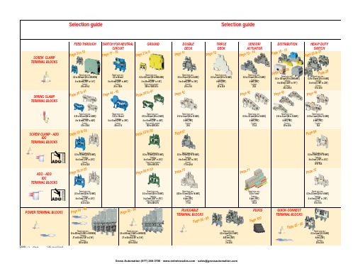
ABB EntrelecSommaireBU0402061SNC 160 003 C0205SummarySelection guide ....................................................................................page 1Screw clamp ........................................................................................page 2Feed through and ground terminal blocks .......................................................page 2 - 5 to 10Single pole, multiclamp terminal blocks..........................................................................page 4Feed through terminal blocks - Double-deck................................................................page 11Feed through terminal blocks - Triple-deck...................................................................page 12Three level sensor, terminal blocks without ground connection...................................page 13Three level sensor, terminal blocks with ground connection ........................................page 14Terminal blocks for distribution boxes, double deck + protection .......................page 15 - 16Interruptible terminal blocks for neutral circuit......................................................page 17 - 18Distribution : phase, ground terminal blocks .......................................................page 19 to 21Single pole or four pole distribution blocks..........................................................page 22 to 24Heavy duty switch terminal blocks with blade......................................................page 25 - 26Heavy duty switch terminal blocks with push-turn knob..............................................page 26Heavy duty switch terminal blocks with contact control pull lever...............................page 29Heavy duty switch terminal blocks with blade - Double-deck .....................................page 27Fuse holder terminal blocks for 5x20 mm (.197x.787 in.) and 5x25 mm (.197x.984 in.)or 6.35x25.4 mm (1/4x1 in.) and 6.35x32 mm (1/4x11/4 in.) fuse s.........................................page 28 - 29Fuse holder terminal blocks for 5x20 mm (.197x.787 in.) and 5x25 mm (.197x.984 in.) fuses -Double-dec k.....................................................................................................................page 27Terminal blocks for test circuits with sliding bridge ......................................................page 30Terminal blocks for metering circuits.............................................................................page 31ESSAILEC terminal blocks.............................................................................................page 32Safety connection terminal blocks ................................................................................page 33Miniblocks for EN 50045 (DIN 46277/2) rail ..........................................................page 34 - 35Spring clamp ......................................................................................page 36Angled terminal blocks - Feed through and ground .....................................................page 36Feed through and ground terminal blocks ...........................................................page 37 to 41Feed through terminal blocks - Double deck ................................................................page 42Terminal blocks for sensors / actuators ........................................................................page 42Terminal blocks for distribution boxes...........................................................................page 43Switch terminal blocks for neutral conductor........................................................page 44 - 45Heavy duty switch terminal blocks with blade..............................................................page 46Fuse holder terminal blocks for 5x20 mm (.197x.787 in.) and 5x25 mm (.197x.984 in.) fuse s....page 47Miniblocks Spring clamp ......................................................................................page 48 to 52ADO - Screw clamp ...........................................................................page 53Feed through and ground terminal blocks ...........................................................page 53 to 56Feed through and ground terminal blocks - Double-deck............................................page 57Heavy duty switch terminal blocks with blade..............................................................page 58Fuse holder terminal blocks for 5x20 mm (.197x.787 in.) and 5x25 mm (.197x.984 in.) fuse s ......page 59 - 60Miniblocks ADO - Screw clamp............................................................................page 61 to 65ADO - ADO .........................................................................................page 66Feed through and ground terminal blocks ...........................................................page 66 to 69Feed through and ground terminal blocks - Double-deck............................................page 70Terminal blocks for sensors / actuators ........................................................................page 71Heavy duty switch terminal blocks with blade..............................................................page 72Fuse holder terminal blocks for 5x20 mm (.197x.787 in.) and 5x25 mm (.197x.984 in.) fuse s ......page 73 - 74Miniblocks ADO - ADO .........................................................................................page 75 to 79Accessories ADO ...........................................................................................................page 80Power terminal blocks .............................................................page 81 to 84Quick-connect terminal blocks .................................................page 85 - 86Terminal blocks for railway applications ................................page 87 to 97Pluggable terminal blocks .....................................................page 98 to 100Accessories......................................................................................page 101Marking..................................................................................page 102 to 104GrossAutomation(877)268-3700··*************************PR30PR3.Z2PR3.G2PR5PR4PR1.Z2Rated wire size :Rated wire size :Rated wire size :Rated wire size :Mounting railsShield terminals forcollector barMarking tableHorizontal Rated wire size :0.5 to 16 mm² (22 to 8 AWG)Rated wire size :Rated wire size :Rated wire size :P a g e t o 29e30 t o 32ag e e3P a ge 8 t o 60a g e6t o 6574P a ge 7 t o 79P a ge 9P a g P a gGrossAutomation(877)268-3700··*************************2ABB Entrelecd010830402051SNC 160 003 C0205MA 2,5/5 - 2.5 mm² blocks - 5 mm .200" spacingAccessoriesGrossAutomation(877)268-3700··*************************3ABB Entrelec D010740402051SNC 160 003 C0205M 4/6 - 4 mm² blocks - 6 mm .238" spacingAccessoriesGrossAutomation(877)268-3700··*************************4ABB EntrelecD011030402051SNC 160 003 C0205M 4/6.3A - 4 mm² blocks - 6 mm .238" spacingM 4/6.4A - 4 mm² blocks - 6 mm .238" spacingGrossAutomation(877)268-3700··*************************5ABB Entrelec D010840402051SNC 160 003 C0205M 6/8 - 6 mm² blocks - 8 mm .315" spacingAccessoriesGrossAutomation(877)268-3700··*************************6ABB EntrelecD010850402051SNC 160 003 C0205M 10/10 - 10 mm² blocks - 10 mm .394" spacingAccessoriesGrossAutomation(877)268-3700··*************************7ABB Entrelec D010860402051SNC 160 003 C0205M 16/12 - 16 mm² blocks - 12 mm .473" spacingAccessoriesGrossAutomation(877)268-3700··*************************8ABB EntrelecD010870402051SNC 160 003 C0205M 35/16 - 35 mm² blocks - 16 mm .630" spacingGrossAutomation(877)268-3700··*************************M 95/26 - 95 mm² blocks - 26 mm 1.02" spacingM 70/22.P - 70 mm² ground block with rail contact - 22 mm .630" spacingSelection35 mm / 1.37"12 mm / 0.47"14-30 Nm / 124-260 Ib.in 1.2-1.4 Nm / 10.6-12.3 Ib.in1000600600415400400577070240 mm 2500 MCM 500 MCM 10 mm 2 6 AWG 6 AWG IEC UL CSANFC DIN0.5 - 160.5 - 100 AWG-600 MCM 2 AWG-500 MCM 50 - 30035 - 24018-6 AWGD 150/31.D10 - 150 mm² blocks - 31 mm 1.22" spacingCharacteristicsD 240/36.D10 - 240 mm² blocks - 36 mm 1.41" spacingSelectionWire size main circuit mm² / AWG VoltageV Current main circuit A Current outputARated wire size main circuit mm² / AWG Rated wire size outputmm² / AWG Wire stripping length main circuit mm / inches Wire stripping length output mm / inches Recommended torque main circuit Nm / Ib.in Recommended torque outputNm / Ib.inSolid Stranded Solid Stranded Wire size output mm² / AWG9.5 mm / .37"0.5-0.8 Nm / 4.4-7.1 Ib.in5003003003220204 mm 212 AWG12 AWG0.2 - 422-12 AWG 22-12 AWG 0.22 - 4IEC ULCSANFC DINCharacteristicsWire size mm² / AWGSolid Stranded D 4/6.T3 - 4 mm² blocks - 6 mm .238" spacingSelectionVoltage V CurrentARated wire sizemm² / AWG Wire stripping length mm / inches Recommended torqueNm / Ib.inM 4/6.T3.P - 4 mm² block - 6 mm .238" spacingD 2,5/6.D - 2.5 mm² blocks - 6 mm .238" spacingD 2,5/6.DL - 2.5 mm² blocks - 6 mm .238" spacingD 2,5/6.DPA1 - 2.5 mm² blocks - 6 mm .238" spacingD 2,5/6.DPAL1 - 2.5 mm² blocks - 6 mm .238" spacingD 4/6... - 4 mm² blocks - 6 mm .238" spacingD 4/6.LNTP - 4 mm² closed blocks - 17.8 mm .700" spacingMA 2,5/5.NT- 2.5 mm² block - 5 mm .200" spacingAccessories**SFB2 : 16 to 35 mm² 6 to 2 AWG H= 3 mm/.12"M 10/10.NT- 10 mm² block - 10 mm .394" spacingAccessories(1) Except for M 35/16 NT (closed block)*SFB1 : 0.5 to 35 mm² 18 to 2 AWG H= 7 mm/.28"**SFB2 : 16 to 35 mm² 6 to 2 AWG H= 3 mm/.12"MB 4/6... - 4 mm² blocks - 6 mm .238" spacingMB 6/8... - 6 mm² blocks - 8 mm .315" spacingMB 10/10... - 10 mm² blocks - 10 mm .394" spacingBRU 125 A - 35 mm² block - 27 mm 1.063" spacingBRU 160 A - 70 mm² block - 35.2 mm 1.388" spacingBRU 250 A - 120 mm² blocks - 44.5 mm 1.752" spacingBRU 400 A - 185 mm² block - 44.5 mm 1.752" spacingAccessoriesAccessoriesBRT 80 A - 16 mm² block - 48 mm 1.89" spacingBRT 125 A - 35 mm² block - 48 mm 1.89" spacingBRT 160 A - 50 mm² block - 50 mm 1.97" spacing9.5 mm / .37"0.5-0.6 Nm / 4.4-5.3 Ib.in4003003002010104 mm 210 AWG 12 AWG 0.5 - 422-10 AWG20-12 AWG0.5 - 2.5IEC ULCSANFC DINMA 2,5/5.SNB - 2.5 mm² blocks - 5 mm .200" spacingCharacteristicsM 4/6.SNB - 4 mm² blocks - 6 mm .238" spacingSelectionWire size mm² / AWGVoltage V CurrentARated wire sizemm² / AWG Wire stripping length mm / inches Recommended torqueNm / Ib.inSolid StrandedM 6/8.SNB - 6 mm² blocks - 8 mm .315" spacing - blade switchingSelectionAccessoriesM 4/8.D2.SF - for fuses 5x20 mm .197x.787 in. and 5x25 mm .197x.984 in. -4 mm² blocks - 8 mm .315" spacingM 4/6.D2.SNBT - 4 mm² blocks - 6 mm .238" spacing - blade switchM 4/8.SF- 4 mm² blocks - 8 mm .315" spacingM 4/8.SFL - 4 mm² blocks - 8 mm .315" spacing12 mm / .472"1.2-1.4 Nm / 10.6-12.3 Ib.in800(1)60060016252510 mm 210 AWG8 AWG0.5 - 1622-10 AWG 22-8 AWG 0.5 - 10IEC ULCSANFC DINCBD2SML 10/13.SF - for fuses 6.35x25.4 mm 1/4x1 in. and 6.35x32 mm 1/4x11/4 in. -10 mm² blocks - 13 mm .512" spacingSelectionAccessoriesCharacteristicsWire size mm² / AWGVoltage V CurrentARated wire sizemm² / AWG Wire stripping length mm / inches Recommended torqueNm / Ib.inSolid Stranded (1) Insulation voltage of terminal block - operating voltage : according to fuse.M 4/6.D2.2S2... - 4 mm² blocks - 6 mm .238" spacing11 mm / .43"0.8-1 Nm / 7.1-8.9 Ib.in50060030306 mm 28 AWG0.5 - 1022-8 AWG0.5 - 6IECULCSANFC DINM 6/8.ST... - 6 mm² blocks - 8 mm .315" spacingCharacteristicsWire size mm² / AWGVoltage V CurrentARated wire sizemm² / AWG Wire stripping length mm / inches Recommended torqueNm / Ib.inSolid Stranded M 6/8.STA - 6 mm² blocks - 8 mm .315" spacing(3)Only for M 6/8.STAM 4/6.ST- 4 mm² blocks - 6 mm .236" spacingBNT...PC...(2) Only for M10/10.ST-SnThe PREM IUM solution for testing the secondary circuits of current or voltage transformers.ESSAILEC, approved by the major electricity utilities, remains the premium choice for the energy market.Implemented in the transformers secondary circuits, ESSAILEC thanks to its intelligent “make before break” design eases and secures any intervention. Cutting the energy supply is avoided with zero risk for the operator.The plug and socket connection cuts cost installation as well as in-situ wiring errors. ESSAILEC is ideal for the wiring of sub-assemblies in the secondary circuits.ESSAILEC terminal blocksProtection relays,Protection relays,Testing :The ESSAILEC socket supplies energy to the protection or counting devices. The insertion of the test plug, which is connected to the measurement equipment, allows the testing of the devices, without perturbing the circuit.ESSAILEC blocks are well adapted to current or voltage measurement :-Current sockets with make before break contacts and pre-wired test plug for current measures-Voltage sockets with open contacts and pre-wired test plug for voltage measures-Up to 4 ammeters or 4 voltmeters connected to the test plugDistributing :The ESSAILEC plug is continuously mounted on the socket to supply current or voltage to secondary circuits sub assemblies.ESSAILEC blocks extreme versatility allow :-Safe current distribution with current socket with mobile contacts since the secondary circuit is not cut when plug is removed-Voltage or polarity distribution with dedicated voltage or polarity socket with closed contactESSAILEC is designed to offer :Great flexibility :-Connection multi contacts « plug and play »-Panel, rail, rack fixed mounting or stand-alone connector -Two wiring technologies, up to 10 mm²Extreme reliability :-Non symmetric blocks -Coding accessories -IP20 design -Locking system -Sealed coverR S T NFor technical characteristics and complete part numbers list, please ask for the ESSAILEC catalog10005006003225254 mm 21.65 mm²12 AWG 13 mm / .51"IECB.SCSANFC DINTS 50-180.5 - 0.8 Nm /4.4 - 7.1 Ib.in0.2 - 422-12 AWG0.22 - 40.5 - 1.50.28 - 1.6580050060041252562.512 AWG 13 mm / .51"0.8 - 1 Nm / 7.1 - 8.9 Ib.inIECB.S CSANFC DINTS 50-180.5 - 1020-12 AWG0.5 - 60.28 - 2.590050060046406510 mm 26 mm² 6 AWG 14 mm / .55"IECB.S UL/CSANFC DINTS 50-181.2 - 1.4 Nm / 10.6 - 12.3 Ib.in0.5 - 1620 - 6 AWG0.5 - 100.28 - 6M 4/6.RS - 4 mm² blocks - 6 mm .238" spacingCharacteristicsWire size mm² / AWGVoltage V CurrentARated wire sizemm² / AWG Wire stripping lengthmm / inches Recommended torque (screw)Nm / Ib.inSolid wire Stranded wire Solid wire Stranded wire Screw clampLugsM 6/8.RS - 6 mm² blocks - 8 mm .315" spacingCharacteristicsWire size mm² / AWGVoltage V CurrentARated wire sizemm² / AWG Wire stripping lengthmm / inches Recommended torque (screw)Nm / Ib.inSolid wire Stranded wire Solid wire Stranded wire Screw clampLugspending M 10/10.RS - 10 mm² blocks - 10 mm .394" spacingCharacteristicsWire size mm² / AWGVoltage V CurrentARated wire sizemm² / AWG Wire stripping lengthmm / inches Recommended torque (screw)Nm / Ib.inSolid wire Stranded wire Solid wire Stranded wire Screw clampLugspending SelectionAccessories(1) Only for block M 4/6.RS (4) For blocks M 4/6.RS and M 6/8.RS(2) Only for block M 6/8.RS(3) Only for block M 10/10.RSDR 1,5/4 - 1.5 mm² blocks - 4 mm .157" spacingDR 1,5/5... - 1.5 mm² blocks - 5 mm .200" spacing。
A20地址线问题
很多稀奇古怪的东西都是由于系统升级时,为了保持向下兼容而产生的,A20 Gate就是其中之一。
在8086/8088中,只有20根地址总线,所以可以访问的地址是2^20=1M,但由于8086/8088是16位地址模式,能够表示的地址范围是0-64K,所以为了在8086/8088下能够访问1M内存,Intel采取了分段的模式:16位段基地址:16位偏移。
其绝对地址计算方法为:16位基地址左移4位+16位偏移=20位地址。
但这种方式引起了新的问题,通过上述分段模式,能够表示的最大内存为:FFFFh:FFFFh=FFFF0h+FFFFh=10FFEFh=1M+64K-16Bytes(1M多余出来的部分被称做高端内存区HMA)。
但8086/8088只有20位地址线,如果访问100000h~10FFEFh之间的内存,则必须有第21根地址线。
所以当程序员给出超过1M(100000H-10FFEFH)的地址时,系统并不认为其访问越界而产生异常,而是自动从重新0开始计算,也就是说系统计算实际地址的时候是按照对1M求模的方式进行的,这种技术被称为wrap-around。
到了80286,系统的地址总线发展为24根,这样能够访问的内存可以达到2^24=16M。
Intel 在设计80286时提出的目标是,在实模式下,系统所表现的行为应该和8086/8088所表现的完全一样,也就是说,在实模式下,80286以及后续系列,应该和8086/8088完全兼容。
但最终,80286芯片却存在一个BUG:如果程序员访问100000H-10FFEFH之间的内存,系统将实际访问这块内存,而不是象过去一样重新从0开始。
为了解决上述问题,IBM使用键盘控制器上剩余的一些输出线来管理第21根地址线(从0开始数是第20根),被称为A20 Gate:如果A20 Gate被打开,则当程序员给出100000H-10FFEFH之间的地址的时候,系统将真正访问这块内存区域;如果A20 Gate被禁止,则当程序员给出100000H-10FFEFH之间的地址的时候,系统仍然使用8086/8088的方式。
NTK3134N Power MOSFET 20 V 890 mA N-Channel 型号说明书
NTK3134NPower MOSFET20 V, 890 mA, Single N−Channel with ESD Protection, SOT−723Features•N−Channel Switch with Low R DS(on)•44% Smaller Footprint and 38% Thinner than SC89•Low Threshold Levels Allowing 1.5 V R DS(on) Rating •Operated at Low Logic Level Gate Drive•These Devices are Pb−Free, Halogen Free/BFR Free and are RoHS CompliantApplications•Load/Power Switching•Interface Switching•Logic Level Shift•Battery Management for Ultra Small Portable Electronics MAXIMUM RATINGS (T J = 25°C unless otherwise stated)Parameter Symbol Value Unit Drain−to−Source Voltage VDSS20V Gate−to−Source Voltage V GS±8VContinuous Drain Current (Note 1)SteadyStateT A = 25°C I D890mAT A = 85°C640t ≤ 5 s T A = 25°C990Power Dissipation (Note 1)SteadyStateTA = 25°C P D450mW t≤ 5 s550Continuous Drain Current (Note 2)SteadyStateT A = 25°C I D750mAT A = 85°C540Power Dissipation(Note 2)T A = 25°C P D310mWPulsed DrainCurrentt p = 10 m s I DM 1.8AOperating Junction and Storage Temperature T J, T STG−55 to150°CLead Temperature for Soldering Purposes(1/8” from case for 10 s)T L260°CStresses exceeding those listed in the Maximum Ratings table may damage the device. If any of these limits are exceeded, device functionality should not be assumed, damage may occur and reliability may be affected.1.Surface mounted on FR4 board using 1 in sq pad size (Cu area = 1.127 in sq[1 oz] including traces)2.Surface mounted on FR4 board using the minimum recommended pad sizeV(BR)DSS R DS(on) TYP I D Max20 V0.20 W @ 4.5 V0.26 W @ 2.5 V890 mA Device Package Shipping†ORDERING INFORMATIONNTK3134NT1G SOT−7234000 / Tape & Reel SOT−723CASE 631AASTYLE 5MARKING DIAGRAM†For information on tape and reel specifications, including part orientation and tape sizes, please refer to our Tape and Reel Packaging Specification Brochure, BRD8011/D.0.43 W @ 1.8 VKF M1KF= Specific Device CodeM= Date Code3 − Drain0.56 W @ 1.5 VNTK3134NT5G SOT−7238000 / Tape & Reel790 mA700 mA200 mASOT−723 (3−LEAD)THERMAL RESISTANCE RATINGSParameter Symbol Max Unit Junction−to−Ambient – Steady State (Note 3)R q JA280°C/W Junction−to−Ambient – t = 5 s (Note 3)R q JA228Junction−to−Ambient – Steady State Minimum Pad (Note 4)R q JA4003.Surface mounted on FR4 board using 1 in sq pad size (Cu area = 1.127 in sq [1 oz] including traces)4.Surface mounted on FR4 board using the minimum recommended pad sizeMOSFET ELECTRICAL CHARACTERISTICS (T J = 25°C unless otherwise specified)Parameter Symbol Test Condition Min Typ Max Unit OFF CHARACTERISTICSDrain−to−Source BreakdownVoltageV(BR)DSS V GS = 0 V, I D = 250 m A20VDrain−to−Source BreakdownVoltage Temperature CoefficientV(BR)DSS/T J I D = 250 m A, Reference to 25°C18mV/°CZero Gate Voltage Drain Current I DSS V GS = 0 V,V DS = 16 VT J = 25°C 1.0m A T J = 125°C 2.0Gate−to−Source Leakage Current I GSS V DS = 0 V, V GS = ±4.5 V±0.5m A ON CHARACTERISTICS (Note 5)Gate Threshold Voltage V GS(TH)V GS = V DS, I D = 250 m A0.45 1.2V Negative Threshold TemperatureCoefficientV GS(TH)/T J 2.4mV/°C Drain−to−Source On Resistance R DS(on)V GS = 4.5 V, I D = 890 mA0.200.35WV GS = 2.5 V, I D = 780 mA0.260.45V GS = 1.8 V, I D = 700 mA0.430.65V GS = 1.5 V, I D = 200 mA0.56 1.2Forward Transconductance g FS V DS = 10 V, I D = 800 mA 1.6S CHARGES, CAPACITANCES AND GATE RESISTANCEInput Capacitance C ISS V GS = 0 V, f = 1 MHz, V DS = 16 V79120pF Output Capacitance C OSS1320Reverse Transfer Capacitance C RSS9.015 SWITCHING CHARACTERISTICS, V GS = 4.5 V (Note 6)Turn On Delay Time t d(ON)V GS = 4.5 V, V DS = 10 V, I D = 500 mA,R G = 10 W 6.7nsRise Time t r 4.8TurnOff Delay Time t d(OFF)17.3Fall Time t f7.4DRAIN SOURCE DIODE CHARACTERISTICSForward Diode Voltage V SD V GS = 0 V, I S = 350 mA T J = 25°C0.75 1.2VReverse Recovery Time t RR V GS = 0 V, d ISD/d t = 100 A/m s,I S = 1.0 A, V DD = 20 V 8.1nsCharge Time t a 6.4Discharge Time t b 1.7Reverse Recovery Charge Q RR 3.0nC Product parametric performance is indicated in the Electrical Characteristics for the listed test conditions, unless otherwise noted. Product performance may not be indicated by the Electrical Characteristics if operated under different conditions.5.Pulse Test: pulse width = 300 m s, duty cycle = 2%6.Switching characteristics are independent of operating junction temperaturesFigure 1. On−Region CharacteristicsFigure 2. Transfer CharacteristicsV DS , DRAIN−TO−SOURCE VOLTAGE (V)V GS , GATE−TO−SOURCE VOLTAGE (V)Figure 3. On−Resistance vs. Gate−to−SourceVoltageFigure 4. On−Resistance vs. Drain Current andGate VoltageV GS , GATE VOLTAGE (V)I D , DRAIN CURRENT (A)Figure 5. On−Resistance Variation withTemperature Figure 6. Drain−to−Source Leakage Currentvs. VoltageT J , JUNCTION TEMPERATURE (°C)V DS , DRAIN−TO−SOURCE VOLTAGE (V)I D , D R A I N C U R R E N T (A )I D , D R A I N C U R R E N T (A )R D S (o n ), D R A I N −T O −S O U R C E R E S I S T A N C E (W )R D S (o n ), D R A I N −T O −S O U R C E R E S I S T A N C E (W )I D S S , L E A K A G E (n A )R D S (o n ), D R A I N −T O −S O U R C E R E S I S T A N C E (W )Figure 7. Capacitance VariationFigure 8. Resistive Switching Time Variationvs. Gate ResistanceDRAIN−TO−SOURCE VOLTAGE (V)R G , GATE RESISTANCE (W )Figure 9. Diode Forward Voltage vs. CurrentV SD , SOURCE−TO−DRAIN VOLTAGE (V)C , C A P A C I T A N C E (p F )t , T I M E (n s )I S , S O U R C E C U R R E N T (A )PACKAGE DIMENSIONSSOT−723CASE 631AA ISSUE DSTYLE 5:PIN 1.GATE2.SOURCE3.DRAINDIM MIN NOM MAX MILLIMETERS A 0.450.500.55b 0.150.210.27b10.250.310.37C 0.070.120.17D 1.15 1.20 1.25E 0.750.800.85e 0.40 BSC H 1.15 1.20 1.25L E NOTES:1.DIMENSIONING AND TOLERANCING PER ASME Y14.5M, 1994.2.CONTROLLING DIMENSION: MILLIMETERS.3.MAXIMUM LEAD THICKNESS INCLUDES LEADFINISH. MINIMUM LEAD THICKNESS IS THE MINIMUM THICKNESS OF BASE MATERIAL.4.DIMENSIONS D AND E DO NOT INCLUDE MOLD FLASH, PROTRUSIONS OR GATE BURRS.eL*For additional information on our Pb−Free strategy and soldering details, please download the ON Semiconductor Soldering and Mounting Techniques Reference Manual, SOLDERRM/D.SOLDERING FOOTPRINT*L20.150.200.250.29 REF 3XL23X2XBOTTOM VIEWSIDE VIEWRECOMMENDEDDIMENSIONS: MILLIMETERS3XON Semiconductor and are trademarks of Semiconductor Components Industries, LLC dba ON Semiconductor or its subsidiaries in the United States and/or other countries.ON Semiconductor owns the rights to a number of patents, trademarks, copyrights, trade secrets, and other intellectual property. A listing of ON Semiconductor’s product/patent PUBLICATION ORDERING INFORMATION。
亚特兰斯声音AA-SMG声音掩蔽模块使用指南
AA-SMG INSTRUCTIONSThank you for purchasing the Atlas Sound AA-SMG masking module. Please read this instruction sheet carefully prior to use to assure a clear understanding of the flexibility the AA120M and AA-SMG offers you. Prior to using any Atlas Sound module please read the AA120M manual prior to use. It is very important for one to know the difference between Amp Direct and Mix Bus modes.KEY FEATURES1. Gain Trim – When the gain is set to max (Clockwise), it is designed that the 70v output will not exceed30v. When fully attenuated the module will have a 1v or less at the 70v outputs2. EQ Trim– The EQ filter operating range is between 1 KHz and 8 kHz with a slope of 6db per octave.When the potentiometer is rotated fully clockwise the variable Hi-Cut filter is at 8 kHz.3. EQ Insert – This TRS insert jack allows you to use an external equalizer for fine tuning of the system.Tip = Send to the EQ, Ring = Return from the EQ and Sleeve is the ground.4. Line Out – This feature allows you use the generator to send a signal to another amplifier formultizone masking. You have the selection of two signal pick up points, Pre EQ or Post EQ. The Pre EQ is a fixed level of 250mv. The Gain, EQ or Insert jack have no effect on the Line Output. If Post EQ is selected, the Line Out signal is affected by the Gain level, EQ setting and the Insert Jack. In PostEQ mode the Line Out signal is the same signal that the AA120M is receiving.5. Post or Pre EQ (jumper J11) – This is for the Line Out jack signal. To select this function, prior toinserting the module into the amplifier, locate (jumper J11) header and place the jumper to the desired selection. Note: You only need to move the jumper one pin over for connection. The middle pin isalways connected.6. Pink and White Noise selection (jumper J5)- Reposition the jumper for desired signal type. Themiddle pin is always connected.7. Amp Direct and Mixed Bus (jumper J10) – This selection determines the master gain feeding theamplifier. It also works in conjunction with Input 6 module selection switch position 5 located on therear panel of the AA120M. We suggest when using the AA-SMG module, the amp and module andAA120M are set to the Amp Direct position. The middle pin is always connected.8. Out to Amp (jumper J8) – If you do not want the AA-SMG signal to go to the AA-120M and want touse the module to feed an external amplifier set this jumper to the OFF position.SET UP - PRIOR TO INSTALLING THE AA-SMG MODULE, YOU MUST DECIDE THE FOLLOWING.1. Select White or Pink Noise (jumper J6)2. Select Amp Direct or Mix Bus operation (jumper J7).3. Turn the module gain pot down counter clockwise (Left direction).4. Turn EQ pot clockwise (Right direction).5. Turn the AA120M power switch off.6.Carefully inset the AA-SMG module into the card guider rails. Push until card is seated and the panels are flush. Secure with screws.7. Select the AA120M input module mode, switch #5 located on the rear panel of the amp.8. Turn all levels down on amplifier. Note if the module is in Amp Direct mode, the only level control youhave for masking is the Gain pot on the AA-SMG. The Master and Input 6 levels on the AA120M are bypassed. All other channels operate normally.9. Turn the amp on. You should be hearing either White or Pink noise.10. Whenever connecting the Line Out or Insert jack, always turn off the AA120M prior to connection.11. Tune the system as needed. Always a good suggestion to refer to Atlas’s white paper on masking.2143TIP (SEND)RING (REC)SLEEVE (GND)CONNECT TO AA-SMGSEND - CONNECTTO EQ INTIP (REC)SLEEVE (GND)RECEIVE - CONNECTTO EQ OUTTIP (SEND)SLEEVE(GND)TIP (HOT)(GND)GRAPH #1#1 AA-SMG – This graph illustrates the comparison of the Line Out White Noise vs. Pink Noise with no EQby passed.GRAPH #2#2 This graph shows the 70v tap output waveform of the AA120M with the AA-SMG in White Noise mode. The graph comparison is indicating the EQ trim engaged (Counterclockwise) or disengaged (Clockwise). Note: This graph also indicates the bandwidth of the AA-SMG through the AA120M amplifier and 70v transformer.GRAPH #3#3 This graph shows the 70v tap output waveform of the AA120M with the AA-SMG in Pink Noise mode. The graph comparison is indicating the EQ trim engaged (Counterclockwise) or disengaged (Clockwise). Note: This graph also indicates the bandwidth of the AA-SMG through the AA120M amplifier and 70v transformer. AA-SMG SPECIFICATIONS:Filter Selection: White, Pink NoiseGain Controls: 70v output AA120, 1v minimum – 30v maximumInput Connection: EQ insert via TRS 1⁄4” jack.Line Output: RCA Unbalanced, Pre EQ fixed 300mV, Post EQ variable 60mv – 1.4VEQ Control: Variable Low Cut 1KHz – 7KHZ, defeatable on Line OutSupply Voltage: 24 VDC, 30 mA internally derived from AA120M amplifierPanel Finish: SilverDimensions: 1.38” W., x 3” H. x 3” D. (35X78X78 mm)。
清华大学操作系统lab1_实验报告
实验1:系统软件启动过程练习1:(1)操作系统镜像文件ucore.img 是如何一步一步生成的?在命令行中输入“make V=”1、首先把C的源代码进行编译成为.o文件,也就是目标文件(红色方框内)2、ld命令将这些目标文件转变成可执行文件,比如此处的bootblock.out(绿色方框内)3、dd命令把bootloder放到ucore.img count的虚拟硬盘之中4、还生成了两个软件,一个是Bootloader,另一个是kernel。
(2)一个被系统认为是符合规范的硬盘主引导扇区的特征:在/lab1/tools/sign.c中我们可以了解到规范的硬盘引导扇区的大小为512字节,硬盘结束标志位55AA练习2:(1)从CPU 加电后执行的第一条指令开始,单步跟踪BIOS 的执行改写Makefile文件lab1-mon: $(UCOREIMG)$(V)$(TERMINAL) -e "$(QEMU) -S -s -d in_asm -D $(BINDIR)/q.log -monitor stdio -hda $< -serial null"$(V)sleep 2$(V)$(TERMINAL) -e "gdb -q -x tools/lab1init"在调用qemu时增加-d in_asm -D q.log参数,便可以将运行的汇编指令保存在q.log 中。
(2)在初始化位置0x7c00 设置实地址断点,测试断点正常。
在tools/gdbinit结尾加上set architecture i8086b *0x7c00 //在0x7c00处设置断点。
continuex /2i $pc //显示当前eip处的汇编指令(3)将执行的汇编代码与bootasm.S 和bootblock.asm 进行比较,看看二者是否一致。
Notice:在q.log中进入BIOS之后的跳转地址与实际应跳转地址不相符,汇编代码也与bootasm.S 和bootblock.asm不相同。
- 1、下载文档前请自行甄别文档内容的完整性,平台不提供额外的编辑、内容补充、找答案等附加服务。
- 2、"仅部分预览"的文档,不可在线预览部分如存在完整性等问题,可反馈申请退款(可完整预览的文档不适用该条件!)。
- 3、如文档侵犯您的权益,请联系客服反馈,我们会尽快为您处理(人工客服工作时间:9:00-18:30)。
A20 Gate v.s A20 Mask
前面文章中有提到A20的一些相關資訊,這邊我就畫一張圖來描述清楚一些概念。
對於圖中我們要區分的是A20 Gate與A20 Mask這兩種不同名詞分別所代表的意義為何。
以下是我自己畫的圖:
這邊描述幾個相關的硬體介面電路所代表的意義: 上圖中可以看到有一個A20 Gate (OR 邏輯匣),他分別有兩支source pin,分別連接到南僑與KBC,且分別由Port 92h與KBC控制狀態,另外還有一支輸出pin連接到CPU的A20 Mask接腳。
A20M # 的由來: The Intel 80486 added a special pin named A20M#, which when asserted low forces bit 20 of the physical address to be zero for all
on-chip cache or external memory accesses. 看的出來從80486後就改成CPU 自己搞....XD
A20 Gate: 一個可以用軟體控制的邏輯匣(AND/OR)...以前A20 gate 輸出腳是接到A20位址線(AND匣,其中一支src pin是接到KBC),後來改接到如上圖的CPU A20M# 後變成OR匣(這邊我不確定是否正確,因為我來不及參與過
去^^)
A20 Gate 只針對A20有影響,對於其他的A21~A31都沒影響。
補充資料:
我曾經看過某個EC Datasheet,裡面有提到有關Port 92h的相關敘述,由於我並不是EC Engineer ,所以只能想像一下可能的實體電路圖:
這張圖裡面的重點在於EC本身也支援Port 92h功能,也就是說可以設定南橋把Port 92h cycle往EC送(選擇使用EC 的Port 92h,此時南橋的Port 92h就失去功效),而EC內有一些組態暫存器,其中有一個是用來控制是否要開啟Port 92h功能,簡單說就是你可以選擇要使用ICH/EC 所提供的Port 92h功能,而使用EC的Port 92h功能時你就必須去設定ICH組態暫存器以及把EC內的Port92_EN_bit 打開。
如果你選擇EC內的Port 92h功能時,從圖中可以看見EC內部也有一個A20 Gate,而他的Source pin是跟KBC電路連接在一起,所以控制的方式會如同我前面畫的那張圖ㄧ樣的控制方式。
這部分補充資料是我自己想像所畫出來的圖,實際的電路圖還是要EC Engineer
才能夠回答,所以僅供大家參考一下。
Reference
維基百科。