Design and Implementation of a Qualitative Simulation Model of lambda Phage Infection
The design and implementation of programmable media gateways

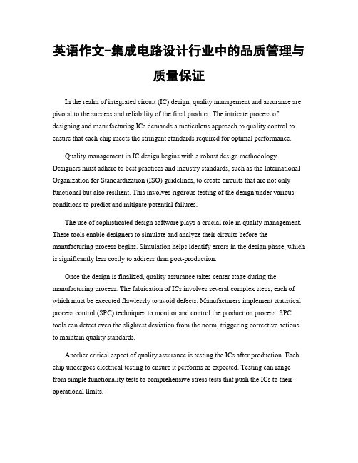
DESIGN AND IMPLEMENTATION OFPROGRAMMABLE MEDIA GATEW AYS Wei Tsang Ooi,Robbert van Renesse and Brian Smith Department of Computer Science,Cornell UniversityIthaca NY14853ABSTRACTTreating the network as a processor that can perform computation has several benefits.Processing at strategic lo-cations in the network may reduce bandwidth requirements. Low-powered devices that are connected to the Internet can be off-loaded as well.In this paper we present Degas,a pro-grammable media gateway system.Degas allows users to upload small programs,called deglets,into a Degas gateway tofilter,transform or mix video streams from a multicast session.We describe a declarative,event-driven program-ming model for writing deglets.We also discuss a simple mechanism used by gateways to optimize and execute the operations specified in the deglets.Finally,a method for selecting a suitable gateway to run deglets is outlined.1.INTRODUCTIONIn the traditional model of distributed computing,nodes on the edges of a network perform computation,and nodes in-side the network move data around.Recently,researchers have been studying how computation can be moved into the network itself.This shift is motivated in part by the increas-ing number of low-powered devices connected to the putationally intensive operations can be moved from these devices to nodes within the network.Performing operations on packets within the network can also improves network efficiency,(e.g.by compressing and decompress-ing data streams across a bottleneck link[17],or transcod-ing a video into a lower bandwidth within a heterogeneous network[2]).Active Networking[14]takes the idea fur-ther by making the nodes with the network programmable. Programmability allows users to extend the network with customized operations,such as application-specific retrans-mission scheme,or new routing protocols.In this paper,we present the design and implementation of a programmable,application-level media gateway called Degas.1Degas allows users to“inject”user-defined pro-This research was supported by DARPA/ONR(contract N00014-95-1-0799),and grants from the National Science Foundation,Kodak,Intel, Xerox,and Microsoft.1Named after French impressionist Edgar Degas.grams,called deglets,into a gateway to perform customized transcoding,filtering and mixing of video and audio streams of a multicast session.Transcoding allows transformation of the media streams into a different format or bit rate,thus allowing heterogeneous hosts to participate in the same ses-sion over connections with different bandwidths.Filtering allows hosts to block streams from certain sources.Mix-ing provides processing on multiple streams.For example, a gateway can merge incoming video streams into a single video stream by creating a”picture-in-picture”or a”quad-splitter”view,or a gateway can switch between different streams in a tele-conference based on who is currently talk-ing.The most significant difference between Degas and pre-vious work is the programmability that Degas provides.In-stead of providing afixed set of services,Degas allows users to upload new functionality into gateways.This simpli-fies deployment of new services,promoting user innovation. Also,it allows users to customize existingservices.Figure1:An example of a Degas system Figure1shows an example of a Degas system.Multi-ple Degas gateways are distributed across the Internet.The existence of these gateways is transparent to the various senders that multicast video streams onto their respective sessions.Such transparency allows current MBone appli-cations such as vic[7]and ivs[15]to be used with Degas without modification.A user who is interested in receiving videos from a ses-sion through Degas runs a Degas client.The client program(called degasclient),is a modified version of vic,extended with abilities to talk to the gateways and a user interface to select and use a deglet.The clientfirst requests a service from Degas.Degas selects a gateway with enough capac-ity.The client then uploads its deglet into this gateway.The gateway joins the session requested by the client and runs the deglet.The processed video stream is sent to a new multicast session,which the client is listening to.A reliable control channel is also established between the client and the gateway.This control channel allows user to interact with the deglet and the gateway,such as to reconfigure de-glet,send user interface events(for instance,mouse click) or migrate the deglet to another gateway.The gateway uses the same control channel to send error messages back to the client for debugging.Figure2shows an example output stream produced by a Degas gateway.1.1.Research ProblemsIn the design and implementation of Degas,several prob-lems arose.We briefly discuss each problem below.The first problem is related to the programming model of de-glets.A deglet must be simple to specify,yet powerful enough to perform useful operations on media streams.We could allow user to write arbitrary code and submit them to the gateway for execution(as in J-Kernel[5]),but we think that this is unnecessarily since Degas is not meant to perform arbitrary computation.We should restrict the pro-grammers to a set of API for manipulating media streams.The second problem concerns the execution of deglets. As media processing involves large amounts of data,nor-mally encoded in a complex format,it is crucial that the gateway executes a deglet efficiently.The optimum way of performing an operation is usually tied to the format of the input streams and output streams.Since the format of input streams may be different and can changed in the middle of a session,we must optimize the deglets differently for dif-ferent streams,and re-optimize when input format changes.The third problem is deciding where to run deglets,to optimize load balancing and use of network resources.Run-ning a deglet at a strategic location can reduce bandwidth consumption significantly.The dynamics of the network environment complicates the problem.Gateways may be created and removed;senders and receivers may join or leave multicast sessions;and available bandwidth of a link changes from time to time.Hence,our solution for locating a gateway must be an adaptive one.Finally,we need to ensure that the system is robust in the face of crashes and badly-behaved deglets,such as one that enters an infinite loop or allocates a huge amount of memory.Resources,including CPU,memory and network bandwidth,must be shared fairly among different deglets. Furthermore,the effect of resource controls on QoS must be minimized.As Degas is still a work in progress,it is not our inten-tion to solve all these problems in this paper.This paper focuses on the programming model and execution model of deglets.We briefly describe our solution for the gateway location problem and refer interested readers to[10]for de-tails.We are still looking at a solution for the resource man-agement problem.anizationThe rest of this paper is organized as follows.The program-ming model is described in Section2.The optimization and execution of deglets are described in Section3.The mech-anism for selecting a gateway to run a deglet is presented in Section4.We provide some performance data in Section5. Ongoing and future work is described in Section6.Finally, we provide an overview of related work in Section7and conclude in Section8.2.PROGRAMMING MODELThe main consideration in selecting a programming model for deglets is simplicity while retainingflexibility and power. We want to make deglet easy to write,so that a user can specify one in a few minutes.This consideration favors the use of scripting languages.For Degas,we chose Tcl[11]. We also chose to use a declarative model for programming deglets.A declarative model lets the user specify what to do,but not how to do it.The user should not be concern with how the deglet is going to be executed.The optimal way to perform the video operations depends heavily on the properties of the input streams,such as the encoding format and sizes.By decoupling the properties of the source media streams from the deglet specification,the same specifica-tion can be used on sources with different properties.Fur-thermore,the users do not have to worry about cases where sources change their transmission properties in the middle of a session.The underlying execution engine determines the best way to perform a task.2.1.ExamplesTo better understand how a deglet is written,we present two examples in Figure3and Figure4.We explain these two examples in detail in the rest of this section.Figure3shows a simple deglet that transcodes a video stream from host into a M-JPEG video stream of quality40.A deglet is a textfile that starts with a list of key-value pairs.The key sources specifies a list of sources we are interested in(line1)us-ing multiple host addresses or a regular expression such as *.In this case,we are only interested in one source.num of sources indicates the maximum numberFigure 2:The left window shows the output from a deglet that creates a picture-in-picture effect.The right windows show the input streams.of sources.input video session indicates the mul-ticast address and port number of the input video session.output format specifies the format of the processed video stream.In this example,we want to receive a 176144M-JPEG stream with quality 40.The remainder of the deglet specifies the operation to perform when an event happens.Line 5to 7define a call-back function to be called whenever a frame is received.The function body is defined using Tcl.We use a prede-fined API frame copy to copy the input frame inf into the output frame outf .frame copy performs the neces-sary scaling and transcoding operations to convert the out-put frames into the format specified above.The argument src id identifies the source of the input stream.Since we have only one source in this case,it is not used.We show how src id is used in our next example.1sources {}2num_of_sources {1}3input_video_session {224.4.4.4/4444}4output_format {JPEG 40QCIF}5recv_frame_callback {src_id inf outf }{6frame_copy $inf $outf 7}Figure 3:A simple deglet.Our second example reads video streams from multiple sources,and outputs a ”split”video stream that consists of video from the current speaker and previous speaker.Video from other sources are filtered.For simplicity,we assumes that the number of sources is always larger than two.We explain this deglet below.Line 1-5specify the input and output parameters.The function init callback in line 6to 12is called at the beginning of the deglet execution.Here,we split the output frame into the left half and the right half,denoted by vari-ables lf and rf respectively.We also initialize the vari-1sources {*}2num_of_sources {*}3input_video_session {224.4.4.4/4444}4input_audio_session {224.4.4.5/4444}5output_format {H261}6init_callback {outf }{7set w2[expr [frame_get_width $outf]/2]8set lf [frame_clip $outf 00$w2[frame_get_height $outf]]9set rf [frame_clip $outf 0$w2$w2[frame_get_height $outf]]10set prev 011set curr -112}13talk_start_callback {src_id}{14if {$src_id !=$curr}{15set prev $curr 16set curr $src_id 17}18}19recv_frame_callback {src_id inf outf }{20if {$src_id ==$curr}{21frame_copy $inf $rf 22}else if {$src_id ==$prev}{23frame_copy $inf $lf 24}25}26destroy_callback {}{27frame_free lf 28frame_free rf 29}Figure 4:A more elaborate deglet example.ables curr and prev that denote the source id the cur-rent speaker and the previous speaker.The function on line 13to 18(talk start callback )is called whenever a talk spurt is detected.The parameter src id indicates the source of the talk spurt.In this function,we simply update the variables curr and prev .Note that variables set inone callback is accessible from other callbacks.In line19 to25,recv frame callback checks if the input frame is from source curr or prev.If it is from either of these, we copy the frame into the left half or the right half of the output frame.Finally,line26to28define the function to call when the deglet exits.We free the memory allocated for lf and rf here.We summarize the lists of available keys,callbacks and frame operations in Table1,2,3respectively.This list is by no means complete,as we plan to add more operations to Degas.In particular,it would be interesting to add vision-related routines such as face detection and object tracking.As illustrated in the two examples above,a deglet is a high-level,declarative style specification.They are short and simple to write.Our most complicated deglet so far,is one that creates a”task bar”of incoming video streams,and let user maximizes or minimizes a video stream by click-ing on the task bar.This is written in under100lines of code.Our examples also illustrate how a user can con-struct the output stream using”frame”as an abstraction, without knowing what the input formats are.The Degas execution module is responsible for translating these spec-ifications into optimized low-level code.We describe the execution of deglets next.3.EXECUTION OF DEGLETSThe Degas execution module is responsible for parsing the deglet specification and for efficient execution of the call-backs.The execution module must recognize optimizations and translate the high-level API into appropriate low-level code.For instance,in Figure3,if the input video stream is also in M-JPEG format,then we can employ compressed domain processing techniques to scale and copy the input frames to output frames efficiently.Furthermore,if the in-put video streams are already in the format requested by the user,the execution module should simply copy the streams without decoding it.We used our low-level,high performance media pro-cessing library called Dali[9]as our target for the translator. The executing module is just a Tcl interpreter extended with Dali commands.Dali consists of a small set of abstractions suitable for representing commonly used video and audio formats.Dali is designed with high-performance in mind, often sacrificing ease of use for efficiency.It exposes inter-mediate structures of video and audio objects,such as DCT blocks,giving programmers(or in our case,the translator) theflexibility of writing highly optimized programs.Dali is also designed with predictability in mind—memory alloca-tions and I/O operations are separated from the processing—so that the programmers have full control over memory us-age and I/O.These features make Dali ideal for forming the basis of our execution module.The optimizations and executions are carried out as fol-lows.We defined a set of optimized versions of Dali sub-routines for each high-level APIs.These high-level APIs are then bound,at run-time,to one of the subroutines based on input and output formats,dimensions and color decimation. Each call to a high-level function will cause the optimized version of the function to be executed.The high-level func-tions are re-bound whenever a change in input video prop-erties is detected.4.SELECTING GATEW AYSBesides the key-values pairs described above,a deglet may contain a set of preconditions.The purpose of preconditions is to allow the user to restrict their deglets to be run on gate-ways that meet certain criteria.The user might impose some restrictions to improve quality of the output,or for security concerns.For example,a user might want to run his deglet on a low-load,high-capacity gateway in the same domain. The currently supported preconditions are as follows: address test:a regular expression that matchesthe host addresses or IP addresses of the gateways el-igible to run the deglet.latency test:the maximum latency between theclient and the gateway.This can prevent an“out-of-the-way”gateway to be assigned to the client.load test:the maximum acceptable CPU load ona gateway.An example of using preconditions is shown in Figure5. This test restricts gateways to those in domain*, or gateways that are within500ms away.Many other tests are possible in the future.For instance,the user might want to select gateways with sufficient memory,or gateways with special hardware for media processing.If the user has to pay for services on a gateway,the user may want to select gateways below a certain price.precondition{[address_test*]||[latency_test]<500}Figure5:An example of using preconditions.When a client requests for service,the preconditions are sent along with the request.A gateway that receives a re-questfirst performs the test,and offers its service only if the test succeeds.sources The sources this deglet is interested in.num of sources Maximum number of sources this deglet can process.input video session,input audio session Specify the input video and audio session respectively.output format,output size,output fps,output bps Specify the format,dimension,frame rate and bit rate of the output stream.precondition The conditions that a gateway must satisfy before it can serve this deglet.description Textual description of what this deglet does.controlling clients Clients that are allowed to control and modify this deglet.Table1:A summary of available keys in deglet specification.init callback(outf)Executed when the deglet starts.outf is the output frame.destroy callback Executed when the deglet stops.new source callback(src id,inf)Executed when a new source is detected.src id is the the source identifier.inf is the input frame.del source callback(src id)Executed when a source identified by src id leaves the session.recv frame callback(src id,inf,outf)Executed when a frame from source src id is received.inf is the received frame.outf is the output frame.mouse click callback(x,y)Executed when a mouse click is detected at coordinate(x,y)on the output window of the client. input resize callback(src id,inf)Executed when input dimension of source src id is changed.talk start callback(src id)Executed when a talk spurt is detected from source src id.talk stop callback(src id)Executed when the beginning of a silence period is detected from source src id.Table2:A summary of available callbacks in deglet specification.frame new w h Return a new frame of width w and height h.frame copy src dest Copy the content of frame src into frame dest,scale if necessary.frame clip f x y w h Create a”virtual”frame from frame f,at offset(x,y)and with dimension w h.frame free f Deallocate frame f.frame get width f Return the width of frame f.frame get height f Return the height of frame f.frame set color f r g b Set the color of the frame f to(r,g,b).Table3:A summary of available frame operations in deglet specification.We have developed a control protocol called the Adap-tive Gateway Location Protocol(AGLP)[10]for locating an appropriate gateway.AGLP optimizes network bandwidth utilization by strategically placing deglets on gateways.A deglet that transcodes to a lower bandwidth format reduces bandwidth and is best run near the source.On the other hand,if a deglet increases bandwidth consumption,it should be run close to the client.AGLP adapts to a changing envi-ronment:senders may join and leave sessions,and gateways may be added or removed.AGLP periodically evaluates the set of eligible gateways,and migrates deglets to better gate-ways when necessary.AGLP handles gateway and client crashes gracefully by only maintaining soft state.5.PERFORMANCETo better understand the overhead introduced by a Degas gateway,we ran some experiments to measure the delay caused by various components in Degas.In our experi-ments,we ran a Degas gateway on a Pentium II266MHz PC.Video streams were sent using vic from hosts connected to the gateway using an100MB Ethernet.Receivers,run-ning either vic or degasclient,were located on the same LAN.We ran NTP[8]on all hosts to get a reasonably accu-rate measurement of end-to-end delay.To verify that our execution model is efficient,we ran an experiment to measure the overhead introduced by our op-timizer and the savings caused by the optimization.In the first experiment,the sender sent a352288H261video stream at8frames per second.The client requested the gateway to transcode the stream into a Motion JPEG video stream of size176144.We measured the time spent in the Dali interpreter for each frame received.In thefirst scenario,we let the optimizer decide how to scale the frames.The optimizer detects that the output size is half the input size,and calls a specialized subrou-tine that shrinks the frame by half.The average time spent in scaling a frame was2.84ms.In the second scenario, we bypassed the optimizer,and called the optimized scal-ing routing ourselves.The average time spent in scaling is2.31ms.Finally,we turned the optimizer off,and used a general purpose scaling routine to scale the frames.The average time spent in scaling a frame increase significantly to43.8ms.This experiment confirmed our belief that the overhead in optimizing is small(1ms),while the savings are significant(about150%).We also measured the total delay introduced by the de-coder,encoder and the Dali interpreter when running dif-ferent deglets.While these measurements were performed on specific deglets only,they give some intuition about the latency introduced by Degas’s processing pipeline.A sum-mary of our measurements is listed in Table4.The ta-ble shows that the delay introduced by the decode-process-encode pipeline is reasonably small.Our next two experiments measured the total end-to-end delay between the source and the receiver.This is a mea-surement between the time a frame is captured at the source and the time the frame is rendered at the receiver.In the first experiment,we collected the data using a degasclient. The gateway was running a deglet that shrinks the size of an incoming Motion JPEG video stream by half at6frames per second(deglet2in Table4).For comparison,we col-lected the same data using vic,which received the origi-nal stream.The end-to-end delays for both experiments are shown in Figure6.The difference between the two mea-surements is small,and is about the same as the total time spent in the decode-process-encode pipeline(27.5ms).We also measured the inter-frame rendering delays in the same experiments.Figure7(a)and Figure7(b)show that Degas gateway introduces some jitter,but are within a tolerable level(within20ms).All our performance measurements shown above are done with a single client.When the gateway serves multiple clients, the jitter increases significantly to as much as200ms.There is also a difference between the QoS received by the clients. The reason is that we have not implemented any resource management in Degas yet.We discuss the current imple-mentation status and developments that we plan to do in the next section.6.IMPLEMENTATION AND FUTURE WORK Degas is implemented using C++and the Mash toolkit[6]. Although still under heavy development,a preliminary pro-totype is available.Simple frame processing API and op-timization scheme is implemented as a”proof-of-concept”. We plan to release Degas into the MBone community in near future.Several interesting problems remain to be solved. We outline some of these problems below.We are looking into how a client can submit multiple deglets that can be composed to perform interesting oper-ations.A deglet that scales down two video sources and merge them into a new video streams is best separated into two stages.Thefirst stage scales the video,and should be run near to the individual sources.The second stage com-bines the video,and should be run near the receiver.By us-ing three deglets(two for scaling and one for merging),we can achieve better bandwidth efficiency than a single deglet could have achieved.We plan to look into how Degas can control the re-sources of the gateways and allow deglets to be executed fairly.We want to prevent a malicious deglet from hogging a gateway.Currently,one can write a deglet that performs frame copy100times for each frame received.Some form of scheduling has to be added so that a gateway can distribute its resources fairly.A particularly interesting is-Operation Input 1Input 2Output %CPU Time 1Shrinking H261352288at 10fps H261176144at 10fps 14%9.76ms 2ShrinkingJPEG 320240at 6fps JPEG 160120at 6fps 18%27.5ms 3Picture-in-picture H261352288at 10fps H261176144at 10fps H261176144at 20fps 40%20.4ms 4Picture-in-picture H261352288at 10fpsH261176144at 10fpsJPEG 176144at 20fps60%32.4msTable 4:Latencies introduced by the decode-process-encode pipeline and the CPU load incurred for different deglets.2040608010012014001002003004005006007008009001000L a t e n c y (m s )Frame NumberdegasclientvicFigure 6:End-to-end Delay between the sender and the re-ceiver.5010015020001002003004005006007008009001000D e l a y (m s )Frame Number(a)5010015020001002003004005006007008009001000D e l a y (m s )Frame Number(b)Figure 7:(a)Inter-frame rendering delay using Degas.(b)Inter-frame rendering delay without Degas.sue is how a gateway can revoke resources from a running deglet when the gateway reallocates its resources.Revok-ing CPU time and bandwidth can affect the QoS received by the client.Revoking allocated memory blocks may re-quire changing the behaviour of the deglet itself.Security is another common concern in extensible archi-tectures.We believe that these concerns can be easily ad-dressed.As in Safe-Tcl [12],we can restrict the set of func-tions available to a deglet.This set can depend on the client that submitted the deglet.In this case,the client would have to sign the deglet,and include its digital certificate (e.g.,X.509[4]).7.RELATED WORKThe idea of running media processing within the network was first described by Turletti and Bolot in [16]and by Pasquale et al in [13].Turletti and Bolot suggested video gateways as a solution for solving the network heterogeneity problem.Pasquale et al proposed a filter propagation mech-anism in multicast dissemination trees.By propagating fil-ters up and down the multicast trees network efficiency may be improved.In [18],Yeadon describes a set of QoS filters that implements the idea in [13].Unfortunately,the sys-tem is not designed to be compatible with the MBone tools,and is therefore not widely deployed.Closer to our work,MeGa [2]is an application-level media gateway that per-forms transcoding on RTP media streams.An advantage of Degas over previous work is that Degas allows user-defined processing on the streams,while MeGa and Yeadon’s QoS filters only support a fixed set of operations.Active Service [3]provides clusters ,which are sets of nodes that provide certain er can request in-stantiation of an application-level service agent,such as the MeGa video gateway,on a cluster.If not available already,the agent can be uploaded.In contrast,Degas provides ex-tensibility at a finer granularity by allowing users to extend an existing service,rather than requiring an entire new ser-vice agent to be uploaded.8.SUMMARYThis paper describes a flexible and extensible media gate-way system called Degas,which allows users to request cus-tomized processing on media streams.Degas is efficient andsimple to use,while being compatible with existing popular MBone tools.Degas is also scalable in the number of gate-ways,and robust in the face of gateway and client crashes.Another contribution of this paper is the Degas program-ming model for writing media processing specification.We use a declarative style,event-driven,scripting-based syn-tax to achieve simplicity,while powerful enough to specify many commonly used operations.We presented a simple model of execution,in which high-level APIs are dynami-cally bound to optimized low-level routines,without requir-ing a full-fledged compiler or optimizer.9.REFERENCES[1]The Third ACM International Multimedia Conferenceand Exhibition(MULTIMEDIA’95),San Francisco, CA,USA,November1995.ACM Press.[2]E.Amir,S.McCanne,and Z.Hui.An applicationlevel video gateway.In Proceedings of the3rd ACM International Multimedia Conference and Exhibition (MULTIMEDIA’95)[1],pages255–266.[3]E.Amir,S.McCanne,and R.Katz.An Active Serviceframework and its application to real-time multimedia transcoding.In Proc.of ACM SIGCOMM,Vancouver, Canada,August1998.[4]C.C.I.T.T.Recommendation X.509.The Directory-Authentication Framework,1988.[5]C.Hawblitzel,C.Chang,G.Czajkowski,D.Hu,andT.von Eicken.Implementing multiple protection do-mains in java.In Proc.of the1998USENIX Annual Technical Conf,pages259–270,New Orleans,LA, 1998.[6]S.McCanne,E.Brewer,R.Katz,L.Rowe,E.Amir,Y.Chawathe,A.Coopersmith,K.Mayer-Patel,S.Ra-man,A.Schuett,D.Simpson,A.Swan,T.L.Tung,D.Wu,and B Smith.Toward a common infrastucturefor multimedia-networking middleware.In Proceed-ings of7th.Intl.Workshop on Network and Operating Systems Support for Digital Audio and Video(NOSS-DAV’97),St.Louis,Missouri,May1997.[7]S.McCanne and V.Jacobson.vic:Aflexible frame-work for packet video.In Proceedings of the3rd ACM International Multimedia Conference and Exhibition (MULTIMEDIA’95)[1].[8]ls.RFC1305:Network time protocol(ver-sion3)specification,implementation,March1992. [9]W.T.Ooi and B.Smith.Dali:A multimedia softwarelibrary.In Proceedings of Multimedia Computing and Networking,San Jose,CA,January1998.[10]W.T.Ooi and R.van Rennese.An adaptive proto-col for locating media gateways.Technical Report submitted to ACMMM2000,Department of Computer Science,Cornell University,2000.[11]J.K.Ousterhout.Tcl and the Tk Toolkit.Addison-Wesley,Reading,MA,USA,1994.[12]J.K.Ousterhout,J.Levy,and B.Welch.The Safe-Tcl security model.Technical Report TR-97-60,Sun Microsystems Laboratories,March1997.[13]J.C.Pasquale,G.C.Polyzos,E.W.Anderson,andV.P.Kompella.Filter propagation in dissemination trees:Trading off bandwidth and processing in con-tinuous media networks.Lecture Notes in Computer Science,846:259–269,1994.[14]D.Tennenhouse,J.Smith,W.Sincoskie,D.Wetherall,and G.Minden.A survey of active network research.IEEE Communications Magazine,pages80–86,Jan-uary1997.[15]T.Turletti.The INRIA videoconferencing system.ConneXions-The Interoperability Report Journal, 8(10):20–24,October1994.[16]T.Turletti and J.Bolot.Issues with multicast videodistribution in heterogeneous packet networks.In Packet Video Workshop,pages F3.1–3.4,Portland, Oregon,September1994.[17]M.Yarvis,A.A.Wang,A.Rudenko,P.Reiher,,and G.J.Popek.Conductor:Distributed adaptation for complex networks.Technical Report CSD-TR-990042,University of California,Los Angeles,Los Angeles,CA,August1999.[18]N.Yeadon,A.Mauthe,D.Hutchison,and F.Garcia.QoSfilters:Addressing the heterogeneity gap.Lecture Notes in Computer Science,1045:227–244,1996.。
英语作文-集成电路设计行业中的品质管理与质量保证
英语作文-集成电路设计行业中的品质管理与质量保证In the realm of integrated circuit (IC) design, quality management and assurance are pivotal to the success and reliability of the final product. The intricate process of designing and manufacturing ICs demands a meticulous approach to quality control to ensure that each chip meets the stringent standards required for optimal performance.Quality management in IC design begins with a robust design methodology. Designers must adhere to best practices and industry standards, such as the International Organization for Standardization (ISO) guidelines, to create circuits that are not only functional but also resilient. This involves rigorous testing of the design under various conditions to predict and mitigate potential failures.The use of sophisticated design software plays a crucial role in quality management. These tools enable designers to simulate and analyze their circuits before the manufacturing process begins. Simulation helps identify errors in the design phase, which is significantly less costly to address than post-production.Once the design is finalized, quality assurance takes center stage during the manufacturing process. The fabrication of ICs involves several complex steps, each of which must be executed flawlessly to avoid defects. Manufacturers implement statistical process control (SPC) techniques to monitor and control the production process. SPC tools can detect even the slightest deviation from the norm, triggering corrective actions to maintain quality standards.Another critical aspect of quality assurance is testing the ICs after production. Each chip undergoes electrical testing to ensure it performs as expected. Testing can range from simple functionality tests to comprehensive stress tests that push the ICs to their operational limits.Moreover, reliability testing is an integral part of quality assurance. It assesses how the IC will perform over time, considering factors like temperature, voltage, and usage patterns. Reliability testing helps predict the lifespan of the IC and ensures that it will not fail prematurely when deployed in critical applications.The commitment to quality extends beyond the production line. Quality management also encompasses the packaging and shipping of ICs. Proper packaging is essential to protect the delicate chips from physical and electrostatic damage during transportation.In conclusion, quality management and assurance in the IC design industry are multifaceted and require a concerted effort from designers, manufacturers, and quality control professionals. By adhering to rigorous standards and employing advanced testing and monitoring techniques, the industry strives to deliver ICs that are not only powerful and efficient but also dependable and durable. This relentless pursuit of quality is what underpins the reliability of the myriad devices that power our modern world. 。
aa-qca-2-1993 标准

aa-qca-2-1993 标准英文回答:The AA-QCA-2-1993 standard is a set of guidelines and requirements for quality control in the manufacturing industry. It provides a framework for organizations to ensure that their products meet the necessary quality standards and customer expectations. The standard covers various aspects of quality control, including process control, inspection and testing, and documentation.One of the key requirements of the AA-QCA-2-1993 standard is the implementation of a comprehensive quality control system. This includes the establishment of clear quality objectives, the identification of key quality indicators, and the development of procedures and processes to monitor and control quality throughout the manufacturing process. By implementing such a system, organizations can ensure that their products consistently meet the required quality standards.Another important aspect of the standard is the requirement for regular inspection and testing of products. This involves conducting thorough inspections at various stages of the manufacturing process to identify any defects or deviations from the required specifications. Additionally, organizations are required to perform testing on a representative sample of finished products to ensure that they meet all the necessary performance and safety requirements.In order to comply with the AA-QCA-2-1993 standard, organizations must also maintain proper documentation of their quality control activities. This includes keeping records of inspections, tests, and any corrective actions taken to address quality issues. By maintaining comprehensive and accurate documentation, organizations can demonstrate their commitment to quality control and provide evidence of their compliance with the standard.中文回答:AA-QCA-2-1993标准是制造业质量控制的一套指南和要求。
Chapter 8 发表relationshlp marketing

Relationship quality itself is seen as a central determinant of customer retention, a concept that has been confirmed empirically for some parts of the service sector.Figure2 presents the structure of the relationship quality construct as conceived。
The implementation aspect of this approach is primarily about finding a set of integrated tools for communicating skills and identifying the requirements which these tools would have to fulfill in terms of a required “ skills mix”.
The relationship marketing literature that the quality of the relationship between the parties involved is an important determinant of the permanence and intensity of this relationship and, therefore, of the success of relationship marketing. The conceptualize relationship quality as a three- dimensional construct, the dimensions are (1) the performance – related perception of quality by the customer. (2) the customer’s trust in the ability and willingness of the supplier to achieve the required performance and (3) the customer’s commitment to the relationship. Postulate complex interactions to exist between these three dimensions. According to their conceptualization of relationship quality, it can be assumed that customers’ performance-related quality perception serves as an antecedent of both trust and commitment (positive relationship), and that trust positively influences the degree of commitment.
Design and Implementation of WIRE1x
Design and Implementation of WIRE1xYu-Ping Wang2,Jyh-Cheng Chen1,2,and Yi-Wen Liu11Department of Computer Science2Institute of Communications EngineeringNational Tsing Hua UniversityHsinchu,TaiwanEmail:{ypwang,jcchen,ywliu}@.twNovember11,2004AbstractThis paper presents the design and implementation of WIRE1x.The WIRE1x is an open-source im-plementation of IEEE802.1x client(supplicant)developed by the Wireless Internet Research&Engi-neering(WIRE)Laboratory.The IEEE802.1x standard defines a port-based network access control toauthenticate and authorize devices interconnected by various IEEE802LANs.The IEEE802.11i alsoincorporates802.1x as its authentication solution for IEEE802.11wireless LANs.The motivation forthe development of WIRE1x is to help the deployment of IEEE802.1x to secure wireless WLANs.Itwould also achieve seamless roaming among different wireless LANs if the new IEEE standards arewidely-deployed.The WIRE1x has been practically used on the wireless LANs deployed at the NationalTsing Hua University and many other places.This paper illustrates the software architecture and designprinciples of WIRE1x so people could comprehend the source code of WIRE1x easily.Keywords:Authentication,Extensible Authentication Protocol(EAP),IEEE802.1x,IEEE802.11i,Wire-less LANs,Security1IntroductionWireless local area network(WLAN)is more and more prevailing in these years.It,however,has been widely reported that security has been a weakness of the current IEEE802.11standards.The Task Group I of IEEE P802.11Working Group is defining802.11i[1,2]to enhance security in current802.11standards. The802.11i incorporates802.1x[3]as the authentication solution for802.11wireless LANs.The IEEE 802.1x standard is a port-based network access control to authenticate and authorize devices interconnected by various IEEE802LANs.The IEEE802.11i is expected to play a critical role in improving the overall security of current and future WLANs.The IEEE802.1x standard has been well-defined.Currently,many manufactures of802.11Access Point (AP)also support802.1x.The802.1x-capable APs have been deployed in many universities,organizations, and companies.To be authenticated by using802.1x,end users also need to be802.1x-capable.Unless 802.1x is embedded in the Operating System(OS),users generally will need to install a802.1x client in order to access to the network.Open1x[4],an open-source implementation of802.1x,supports Mac OS X, FreeBSD,OpenBSD,and Linux.Many users,however,are using MS Windows.They need a802.1x client software to access to the802.1x-based LANs.We therefore develop the WIRE1x to support various versions of MS Windows.As the name suggested,WIRE1x is an open-source implementation of IEEE802.1x client (supplicant)∗developed by the Wireless Internet Research&Engineering(WIRE)Laboratory†.Currently,WIRE1x supports MS Windows XP(without service pack and with service pack1),Win-dows2000,Windows ME,and Windows98.It provides EAP-MD5[5],EAP-TLS[6],EAP-TTLS[7], and PEAP[8].WIRE1x works with freeRADIUS[9].The implementation of WIRE1x is based on Open1x,and is developed by using MS Visual C++.It utilizes libraries of WinPcap[10],Libnet[11], and OpenSSL[12].Both source code and executable code of WIRE1x can be downloaded freely from .tw/wire1x/.This paper presents all components of WIRE1x exhaustively.The objec-tive of this paper is to share our experience on implementing802.1x supplicant.By reading this paper,one should easily comprehend the source code of WIRE1x.1.1Motivation and ContributionCurrently,the National Tsing Hua University(NTHU)has deployed WLANs and is using IEEE802.1x and RADIUS[13]to authenticate users.Most users at NTHU are using MS Windows.However,we perceive that none of the IEEE802.1x client software meet all demands for users of MS Windows in the marketplace up to now.Therefore,a major motivation for the development of WIRE1x is to solve the existing problem and then help IEEE802.1x to be deployed rapidly.It would also expedite the objective of seamless roaming among different wireless LANs if the new IEEE standards are widely-deployed.The contributions include:•WIRE1x is a free as well as open-source software.We believe open source is essential for any securityrelated software because it can be examined as you wish.•WIRE1x provides various EAP(Extensible Authentication Protocol)[14]based authentication meth-ods,including EAP-MD5,EAP-TLS,EAP-TTLS,and PEAP.•WIRE1x can work with various versions of MS Windows,including Windows XP,2000,ME,and98.•WIRE1x works well with various types of WLAN cards.Please see the webpage at.tw/wire1x/compatible.htm.We believe that WIRE1x is a good choice for people eager for IEEE802.1x client software.Since WIRE1x was released on June18,2003,the website of WIRE1x has been visited for more than15,000 times.There have been more than2,100downloads of source code and3,800downloads of executable code up to November2004.The rest of the paper is organized as follows.Section2provides a brief overview of IEEE802.11i and IEEE802.1x.Section3describes other available implementations of802.1x.Section4discusses the design and implementation of WIRE1x in details.Section5presents the real-world applications of WIRE1x. Section6summarizes the paper.2Overview of IEEE802.11iThis section briefly reviews WLAN security and IEEE802.11i.For more details,please refer to[1,2].The IEEE802.11standard is one of the most widely adopted standards for broadband wireless Internet access.However,the security consideration over wireless environment is more complicated than that in wired environment.Due to the wide-open nature of wireless radio,the network is more vulnerable.The original IEEE802.11standard has defined the following two basic security mechanisms for securing the ac-cess to IEEE802.11networks:(1)entity authentication including open system authentication and shared key authentication,and(2)Wired Equivalent Privacy(WEP).Nevertheless they are all proved to be vulnerable.To enhance the security in IEEE802.11,the IEEE802.11i has been proposed.In addition to introducing key management and establishment,it also defines encryption and authentication improvements.In order to manage security keys automatically,the IEEE802.11i has defined key management and establishment algorithms.As conventional WEP is known to be vulnerable,the IEEE802.11i has specified enhanced encryption algorithms to provide stronger privacy.The IEEE802.11i also incorporates IEEE802.1x as its authentication enhancement.The following sections briefly discuss Encryption Algorithm and802.1x. 2.1Encryption AlgorithmTwo algorithms,Temporal Key Integrity Protocol(TKIP)and Counter mode with CBC-MAC Protocol (CCMP)have been proposed.Both TKIP and CCMP provide enhanced data integrity and confidentiality over IP,initially referred to as WEP2,is also based on RC4encryption as that in WEP.It however3is implemented in a different way that addresses the vulnerabilities of IP can be adopted into the older IEEE802.11products through relatively simplefirmware upgrade.This is especially favorable for IP is optional in IEEE802.11i.In addition to TKIP which is considered as a short-term solution for WLAN security,the IEEE802.11i has also defined CCMP as a long-term solution.The CCMP employs the stronger encryption of Advanced Encryption Algorithm(AES)[15]which uses the CCM mode[16]with a128-bit key and a128-bit block size of operation.The CCM mode combines Counter-Mode(CTR)and Cipher Block Chaining Message Authentication Code(CBC-MAC).The CTR is used to encrypt the payload and the Message Integrity Code (MIC)to provide confidentiality service.The CBC-MAC computes the MIC to provide authentication and integrity services.Although the CCMP could provide much stronger security services,it requires additional hardware(co-processor)to improve encryption performance.Unlike TKIP,CCMP is mandatory in IEEE 802.11i.2.2802.1xThe IEEE802.1x defines a mechanism for port-based network access control.It is based upon EAP to provide compatible authentication and authorization mechanisms for devices interconnected by IEEE802 LANs.As depicted in Fig.1,there are three main components in the IEEE802.1x authentication system.In a WLAN,supplicant usually is a Mobile Node(MN).AP usually represents an authenticator.Authentication, Authorization,and Accounting(AAA)server such as RADIUS server is the authentication server.The port in802.1x represents the association between a MN and an AP.Both supplicant and authenticator have a Port Access Entity(PAE)that operates the algorithms and protocols associated with the authentication mechanisms.In Fig.1,the authenticator’s controlled port is in unauthorized state.That is,the port is open.Messages will be directed only to the Authenticator PAE,which will further direct802.1x messages to the authentication server.The authenticator PAE will close the controlled port after the supplicant is authenticated successfully.Thus,the supplicant is able to access to other services through the controlled port.Based upon EAP,the IEEE802.1x standard can use a number of authentication mechanisms.The authentication mechanisms are outside the scope of the IEEE802.1x.Many authentication mechanisms such as Message Digest5(MD5),Transport Layer Security(TLS),Tunneled TLS(TTLS),Protected Extensible Authentication Protocol(PEAP),and Lightweight Extensible Authentication Protocol(LEAP)[17]could be used.The IEEE802.1x also defines EAP over LANs(EAPOL)to encapsulate EAP messages between the supplicant and the authenticator.The authenticator PAE relays all EAP messages between the supplicant and the authentication server.The IEEE802.1x is utilized to enforce the use of specific authentication mechanism and to route authentication messages properly,while the authentication mechanisms define the actual authentication exchanges that take place.Fig.2shows a typical802.1x message exchange.The associated PAE state transitions in supplicant and authenticator are specified in Fig.3and Fig.4,respectively.In Fig.2,the digits in rectangles refer to the4supplicant PAE states in Fig.3,and digits in circles refer to the authenticator PAE states in Fig.4.In Fig.2, RADIUS is served as the authentication server.This does not limit the use of other AAA servers such as Diameter[18]as the authentication server.Detailed discussion of Figs.2–4can be found in[2].3Related WorkThis section discusses related implementations of802.1x in the marketplace.Table1lists most of commercial products of802.1x supplicant.The supported operating systems and EAP authentication methods are also specified.Although some of them provide pre-compiled binary code for non-commercial use or free trial,basically they are not freeware.In addition,the source code are not open to public either.Table2lists the open-source implementations of802.1x supplicant.The Open1x is designed to work with Linux although its earlier versions also supported BSD and Mac OS.Because many users are eager for a free software of802.1x supplicant to work with various versions of MS Windows,we therefore have developed WIRE1x.Both Open1x and WIRE1x are licensed under the BSD License and GNU General Public License(GPL).In addition to Open1x and WIRE1x,a newly initiated project called wEAP[19]is writing open-source plug-ins for MS Windows2000and XP.Unlike wEAP,the WIRE1x is an application program for various versions of MS Windows.Table3lists the authentication servers and the EAP they support.Except freeRADIUS,all of them are commercial products.As indicated in Table3,the freeRADIUS supports many authentication mechanisms. Others only support some of them.A user would not be authenticated if there is no common authentication mechanism supported in both supplicant and authentication server.This will limit the roaming capability significantly.The supplicant software is indispensable to IEEE802.1x standard.We observe that the success of 802.1x would greatly depend on end users.We believe that a free802.1x supplicant software which works with various versions of MS Windows and supports most of EAP authentication methods will boost the deployment of802.1x,and thus802.11i.Therefore,we have developed WIRE1x and hope that most users could access to WLANs with a more secure way.4WIRE1xThe software architecture of WIRE1x can roughly be divided into three components as illustrated in Fig.5: (1)supplicant PAE state machine,(2)EAP and authentication mechanisms,and(3)WinPcap,Libnet,and OpenSSL.The supplicant PAE state machine follows the specification defined in the IEEE802.1x for a supplicant.The state machine is also depicted in Fig.3.As the name suggested,the EAP and authentication mechanisms support various authentication mechanisms in EAP including EAP-MD5,EAP-TLS,EAP-TTLS,and PEAP.The WinPcap[10]and Libnet[11]are two open-source libraries which are responsible for capturing and writing packets to and from the data link layer.Additionally,the OpenSSL[12]is another5open-source library which is used only for TLS-based authentication methods.The following sections discuss the three main components in details.4.1Supplicant PAE State MachineThe supplicant PAE state machine is the core of any implementation of802.1x supplicant.It specifies the behavior of the supplicant and interacts with the authenticator.Again,the supplicant PAE state machine is specified in Fig.3and the source code can be downloaded from .tw/wire1x/.In WIRE1x,roughly speaking,it is implemented in fourfiles:dot1xgeneric.cpp.All variables of state machine are defined in dot1xframe frame(),send frames(),and so on.In os frame()employs pcap frame()employs libnet link() to send EAP frames.4.2EAP and Authentication MechanismsThis section introduces the Extensible Authentication Protocol(EAP).In addition,we also use the message exchanges depicted in Fig.2and the associated state machines shown in Fig.3and Fig.4to demonstrate a typical authentication procedure of WIRE1x.Additionally,we provide detailed description of several EAP authentication methods implemented in WIRE1x.4.2.1OverviewEAP[14]is a general protocol for authentication.It supports multiple authentication methods,such as token card,Kerberos[20],one-time password,certificate,public key authentication,and smart card.Fig.6shows that there can be many different authentication methods in the Authentication Layer.The authentication methods are based upon EAP.Any new authentication mechanisms can be added easily.The WIRE1x is expected to be versatile in authentication mechanisms.It has been implemented to support the most common authentication methods,including EAP-MD5,EAP-TLS,EAP-TTLS,and PEAP.Next,we present a typical authentication procedure of WIRE1x by using Figs.2–4.er opens and selects the device to be authenticated by pcapwrite3.When the AP receives EAPOL-Start,it will reply EAP-Request/Identity to obtain the MN’s identity.When the MN captures the EAP frame by pcap decode decodedecode decodesupplicant and requests the supplicant’s certificate.The supplicant validates the server’s certificate and responds an EAP-Response which contains the supplicant’s certificate.The supplicant also initiates the negotiation for cryptographic material.After the supplicant’s certificate is validated,the server responds the cryptographic material for the session.The session keys derived in both ends could be used for data encryption.The EAP-TLS is implemented in tls funcs.cpp.The GUI of EAP-TLS is shown in Fig.9 which consists of three major input objects.The select button on the upper-right corner of the GUI is responsible for choosing the certificate in the supplicant.We use several functions from Windows SDK (Software Development Toolkit)in mfcDlg.cpp as below:1.The CertOpenSystemStore()for opening a system certificate store.2.The CryptUIDlgSelectCertificateFromStore()for selecting a new certificate using UI.3.The CertGetNameString()forfinding and printing the name of the subject of the certificate just re-trieved.4.The CertOpenStore()for opening the certificate store to be searched.5.CertCloseStore()for closing the system certificate store.To use these functions,the system headerfiles of wincrypt.h and cryptuiapi.h must be included.Ad-ditionally,the libraries of crypt32.lib,advapi32.lib,and cryptui.lib must be linked.While we use these functions to get the certificate structure,we must replace SSL usefile()bySSL use ASN1()in eapcrypt.cpp to receive the structure provided by Windows SDK func-tions.The second object is the password for the selected certificate.Before using the supplicant’s certificate, the user must type in the correct password for the certificate.The third object is to select the proper network interface to be authenticated.This is same as that in EAP-MD5.4.2.4EAP-TTLSThe EAP-TTLS[7]extends EAP-TLS to exchange additional information between client and server by using the secure tunnel established by TLS negotiation.A EAP-TTLS negotiation comprises two phases: the TLS handshake phase and the TLS tunnel phase.During phase one,TLS is used for client to authenticate server.Optionally,the server can also authenticate the client.Same as that in EAP-TLS,the authentication is done by using certificates.A secure TLS tunnel is also established after the phase-one handshake.In phase two,the secure TLS tunnel can be used for other information exchanges,such as additional user authentication key,communication of accounting information,etc.In a WLAN environment,the EAP-TTLS usually is used as follows.First,TLS is used for a supplicant to authenticate the authentication server by using certificate.Once the authentication server is authenticated,8the authentication server authenticates the supplicant by the supplicant’s username and password.The user-name and password are carried in the attribute-value pairs(A VPs)defined by the AAA server,which usually is a RADIUS server or Diameter server.The message exchanges are protected by the TLS tunnel estab-lished in phase one.The authentication of supplicant in phase two can use any non-EAP protocols such as PPP Authentication Protocols(PAP)[23],PPP Challenge Handshake Authentication Protocol(CHAP)[24], Microsoft PPP CHAP Extensions(MS-CHAP)[25],or Microsoft PPP CHAP Extensions,Version2(MS-CHAP-V2)[26].Because only the authentication server needs to have a valid certificate,EAP-TTLS is more manageable than EAP-TLS.The EAP-TTLS in WIRE1x is implemented in tls funcs.cpp,ttlsphase2.h,and ttlsphase2.cpp. The GUI of EAP-TTLS shown in Fig.10consists offive major input objects.The unprotected ID is used to represent the supplicant’s identify for phase-one handshake.The username and password are used for phase-two authentication.The user also needs to choose one of the authentication protocols which can be PAP,CHAP,MS-CHAP,or MS-CHAP-V2for phase-two authentication.Similarly,the user also needs to select the proper network interface to be authenticated.4.2.5PEAPThe PEAP[8]provides an encrypted and authenticated tunnel based on TLS.The EAP messages encapsu-lated inside the TLS tunnel,therefore,are protected against various attacks.Similar to EAP-TTLS,PEAP also comprises two phases.Infirst phase,a TLS session is negotiated.The client also authenticates the server by using certificate.Optionally,the server can also authenticate the client.In second phase,EAP messages are encrypted by using the key negotiated in phase one.The basic idea of PEAP and EAP-TTLS are identical.However,PEAP can only use EAP protocols in second phase,while EAP-TTLS can use EAP or non-EAP protocols.When using PEAP in WLANs,typically an authentication server is authenticated by a supplicant based on the server certificate.A secure TLS tunnel is also created.A supplicant is then authenticated by using username and password,which are protected by the TLS tunnel.The PEAP in WIRE1x is implemented in tls funcs.cpp,eapmschapv2.h,eapmschapv2.cpp, peapphase2.h,and peapphase2.cpp.The GUI of PEAP shown in Fig.11consists of three major input objects.A user must type in username and password for phase-two authentication.Currently,only EAP-MS-CHAP-V2[27]‡is supported.A user also needs to select the proper network interface to be authenticated.To conclude Section4.2,we provide comparison of the authentication mechanisms presented in this section by Table4.Table5further compares the TLS-based protocols.4.3Open-Source LibrariesThis section describes the open-source libraries used in WIRE1x.WinPcap and Libnet are used to cap-ture/write packets from/to data link layer.OpenSSL is used for TLS-based authentication methods.4.3.1WinPcapThe WinPcap[10]is used for packet capture and network analysis in Win32platform.It includes a kernel-level packetfilter,a low-level dynamic link library(packet.dll),and a high-level and system-independent library(wpcap.dll which is based on libpcap version0.6.2).It is in charge of the following tasks:1.The pcapdispatch()in ospcap()in osclose()in osopen generic.cpp selects promiscuous mode or non-promiscuous mode for the network interface.4.3.2LibnetThe Libnet[11]is a generic networking API that provides access to several protocols.It is used only for libnet link()in osCTX verifyCTX certificateCTX certificate3.The SSL usefile()loads the client private key in PEM format.This function is usedby EAP-TLS only.4.4GUIThe GUI is developed by MFC program of MS Visual C++.There arefive GUI programs in the WIRE1x project.One of them is for the main program as shown in Fig.12,which is responsible for selecting an EAP authentication method.The other GUIs are for the programs of md5.exe,tls.exe,ttls.exe,and peap.exe, which have been shown earlier.We also use thread function in mfcDlg.cpp to avoid blocking when GUI is executing.Please refer to the source code for details.5Real-World ApplicationsThe WIRE1x has been practically used at the National Tsing Hua University(NTHU).At NTHU,each department/institute is responsible for the deployment of networking facilities in its own building(s).The university has no authority over the areas owned by the department/institute.The Computer&Communica-tion Center(CCC)operated by the university is responsible for the networking facilities in public areas on campus.Thus,following standards is essential for roaming and integration of WLAN environments even inside the same university.Both CCC and the Computer Science(CS)department at NTHU have deployed WLANs by using 802.1x and RADIUS to authenticate users.To roam between different administrative domains,both of their RADIUS servers could be connected together as shown in Fig13.Assuming a user abc has an account abc@.tw owned by the CCC.Once the user roams into the WLANs covered by the CS department, the CS RADIUS server can authenticate the user by relaying the authentication messages back to the CCC RADIUS.The CS RADIUS server acts as a proxy client to the CCC RADIUS server.With only one account at CCC,the user still could roam into other WLANs.6SummaryThis paper presents the motivation and contribution of WIRE1x.The implementation are discussed in de-tails.By reading this paper,one should be able to examine the source code of WIRE1x in addition to using it.Currently,WIRE1x supports several wireless cards and provides various authentication methods,includ-ing EAP-MD5,EAP-TLS,EAP-TTLS,and PEAP.It is versatile comparing to many other implementations of IEEE802.1x supplicant.WIRE1x has been downloaded worldwide.We hope WIRE1x will not only be used at NTHU,but will also play a crucial role for WLAN security and the interoperability of WLANs among different universities,companies,and organizations.11AcknowledgmentsWe thank other members of the WIRE Lab,especially Chin-Hsing Lin,Wen-Ting Wu,and Jui-Hung Yeh, for helping the development of WIRE1x.We also thank the support of the Computer and Communica-tion Center,National Tsing Hua University,and the Computer Center,Department of Computer Science, National Tsing Hua University.References[1]IEEE Std802.11i,“Part11:wireless LAN medium access control(MAC)and physical layer(PHY)specifications.Amendment6:medium access control(MAC)security enhancements,”July2004. [2]J.-C.Chen,M.-C.Jiang,and Y.-W.Liu,“Wireless LAN security and IEEE802.11i,”IEEE WirelessCommunications(Accepted and to appear,2004).[3]IEEE Std802.1X-2001,“IEEE standard for local and metropolitan area networks,port-based networkaccess control,”Oct.2001.[4]“Open1x.”/.[5]R.Rivest,“The MD5message-digest algorithm.”IETF RFC1321,Apr.1992.[6]B.Aboba and D.Simon,“PPP EAP TLS authentication protocol.”IETF RFC2716,Oct.1999.[7]P.Funk and S.Blake-Wilson,“EAP tunneled TLS authentication protocol(EAP-TTLS).”IETF InternetDraft,<draft-ietf-pppext-eap-ttls-05.txt>,work in progress,July2004.[8]A.Palekar,D.Simon,J.Salowey,H.Zhou,G.Zorn,and S.Josefsson,“Protected EAP proto-col(PEAP),version2.”IETF Internet Draft,<draft-josefsson-pppext-eap-tls-eap-10.txt>,work in progress,Oct.2004.[9]“freeRADIUS.”/.[10]“WinPcap.”http://winpcap.polito.it/.[11]“Libnet.”/.[12]“OpenSSL.”/.[13]C.Rigney,S.Willens,A.Rubens,and W.Simpson,“Remote authentication dial in user service(RA-DIUS).”IETF RFC2865,June2000.[14]L.Blunk and J.V ollbrecht,“PPP extensible authentication protocol(EAP).”IETF RFC2284,Mar.1998.12[15]FIPS197,“Advanced encryption standard(AES).”National Institute of Standards and Technology(NIST),Nov.2001.[16]D.Whiting,R.Housley,and N.Ferguson,“Counter with CBC-MAC(CCM).”IETF RFC3610,Sept.2003.[17]“Lightweight extensible authentication protocol-LEAP.”/.[18]P.Calhoun,J.Loughney,E.Guttman,G.Zorn,and J.Arkko,“Diameter base protocol.”IETF RFC3588,Sept.2003.[19]“wEAP.”/.[20]J.Kohl and C.Neuman,“The Kerberos network authentication service(v5).”IETF RFC1510,Sept.1993.[21]T.Dierks and C.Allen,“The TLS protocol,version1.0.”IETF RFC2246,Jan.1999.[22]Cisco Systems,“White paper:EAP-TLS deployment guide for wireless LAN networks.”/,2004.[23]B.Lloyd and W.Simpson,“PPP authentication protocols.”IETF RFC1334,Oct.1992.[24]W.Simpson,“PPP challenge handshake authentication protocol(CHAP).”IETF RFC1994,Aug.1996.[25]G.Zorn and S.Cobb,“Microsoft PPP CHAP extensions.”IETF RFC2433,Oct.1998.[26]G.Zorn,“Microsoft PPP CHAP extensions,version2.”IETF RFC2759,Jan.2000.[27]V.Kamath and A.Palekar,“Microsoft EAP CHAP extensions.”IETF Internet Draft,<draft-kamath-pppext-eap-mschapv2-01.txt>,work in progress,Apr.2004.[28]B.Kaliski,“Privacy enhancement for Internet electronic mail:part iv:key certification and relatedservices.”IETF RFC1424,Feb.1993.[29]ITU-T Rec.X.690,“ASN.1encoding rules:specification of basic encoding rules(BER),canonicalencoding rules(CER)and distinguished encoding rules(DER),”July2002.13Table1:Commercial802.1x supplicantsVendor EAP Supported Meetinghouse MD5,LEAP,TLS,TTLS,PEAPMS Windows98/ME/2000/XPMicrosoft TLS,PEAPMS Windows XPMicrosoft TLS,PEAPMS Windows/Mac OS/LinuxsecureW2TTLSTable2:Free802.1x supplicantsName EAP Supported Open1x MD5,TLS,TTLS,PEAP,SIM MS Windows98/2000/ME/XP(including SP1)EAP SupportedFunk SoftwareInterlink NetworksHewlett-PackardMicrosoftCisco SystemsfreeRADIUSEAP-MD5EAP-TTLSNo Public key(certificate)Supplicant Public key Certificate Authentication(certificate or orsmart card)EAP protocolsNo YesDynamic Key Yes YesDelivery14Table5:Comparison of TLS-based methodsEAP-TTLS(RFC2716)(Internet draft)(1)Establish TLSsession and between client Basic and TTLS serverfor both client(2)Run EAP Architecture attribute-value-pairsTLS tunnelclient and serverServer RequiredRequired Optional CertificateProtection of User Yes,protectedby TLSFigure1:Supplicant,authenticator,and authentication server15。
Areas of achievements

Working Experience01/2007–09/2007 Interaction Designer (Intern) Philips Applied Technologies, NetherlandsResponsibility: Design and implementation of an interactive solution for controlling the domestic lighting system. Areas of achievements: - User Centered Design - System interaction - Usability test and evaluation 10/2005–12/2006 Trainee Research Assistant User System Interaction Program, TU/e, NetherlandsResponsibility: Design and evaluate user interfaces of products, services, and systemsby scientific methods and techniques .Research area: Human Factors, Tangible Interface, Information Visualization,Multimodal Perception, Computer Supported Cooperative Work(CSCW), SemanticWeb, Persuasion and Trust, Speech InterfacesAreas of achievements:- The design and conducting of a field study- Data collection using questionnaires, interviews and controlled experiments- User interface design- Prototyping of interactive systems (video prototype and working prototype)- Usability test and evaluation: qualitative and quantitative analysis12/2003–12/2004 Software Engineer (Intern) WIBU-SYSTEMS AG, GermanyResponsibility: Design and implement protocols for content protection using a tamper-resistant hardware token.Areas of achievements:- Digital Rights Management- Tamper-resistant hardware- Streaming technology05/2004–07/2004 System Administrator (Part-Time) Comec Consultancy B.V., NetherlandsResponsibility: Perform system maintenance and network management, design andmaintenance of the company website.Education10/2005 – 10/2007 Professional Doctorate in Engineering (PDEng) in User System InteractionEindhoven University of Technology (TU/e), The Netherlands09/2002–04/2005 Master of Science (MSc) in TelematicsUniversity of Twente, The Netherlands • Average:7.3/1009/1998–07/2002Bachelor of Engineering in Computer ScienceJiangsu University of Science and Technology (JUST),China • Average GPA: 88/100 GPA of Core Course: 91/100Jieyin Cheng 程洁音TEL: +31 (0)616 155 125, EMAIL : J.Cheng@tm.tue.nl ADDRESS : Pastoor Petersstraat 89A, 5612WB, Eindhoven, The NetherlandsTechnical SkillsProgramming C/C++, Java, Visual Basic, PHP, x86 assembly language Web Design HTML, XML, CSSSDK Windows Media Format (WMF) Software Development Kit System Modelingand ValidationLanguageMatlab, SPIN, UppaalProtocolSpecificationSDL (Specification and Description Language)Database MySQLOS Windows 9x/NT/2000/XP, MS-DOSProtocol TCP/IP, UDP, SNMPE-commerce Testbed StudioSoftware Application Microsoft Office; Macromedia Flash and Dreamweaver; Adobe Illustrator, Photoshop and Premiere; SPSS; Noldus Observer; Camtasia Studio; MaxMSP; Cool EditHardware Phidgets; CodeMeterProject ExperienceHuman-Computer Interaction related projectRedesign of a medical website for diabetic teenagers (12 -16 years old )Design of a day-to-day support system for diabetic patientsDesign of a multimodal non-visual interface for assisting blind people in finding public transport Design of a tangible interface for assisted navigation in DisneylandDesign of a handheld intelligent map for assisted navigation in DisneylandDesign of an interactive table for customized, easy and discreet socializing for guests in a pub/restaurantDesign of a communication platform for elderly peopleDesign of an information visualization system, in the form of group photo-sharingDesign of a visualization system for clothes-fitting in fashion shopsDesign of a speech interface for interactive public display in the context of fashion shoppingDesign of an intelligent coat for 'tai chi quan' practitionersDesign of a semantic web application for 'animal kingdom' (one version for PC and one version for handheld devices)Design of an internet game for energy savingDesign of a guideline for perceived privacy and personal security in 'ambient intelligence for the networked home environment' (Amigo, Philips Research) projectDesign of an "e-housekeeper" for students or young people who share house facilities in an intelligent home environmentUsability study of a parking payment systemUsability analysis of a website using the co-discovery methodSystematic observation and study at a sport centerExperimental study of display size and menu structureMaster of Science project : “StreamTo: Streaming content using tamper-resistant token”In this project, a content protection platform ‘StreamTo’ is achieved for musicprotection. StreamTo uses tamper-resistant hardware tokens to generate thekey stream needed to decrypt encrypted music streams. A security analysis isprovided and two prototype implementations (Java iButton and CodeMeter)with a performance assessment are presented. The results show that thesystem is both effective and efficient. (Development tools: Windows MediaFormat (WMF) SDK, CodeMeter SDK, Visual Studio)Bachelor of Engineering Final Year project : “Analysis of cell images based on mathematical morphology”In this project, the theory of mathematical morphology is applied to process the original images of cells. Through the erosion method, the overlapping cells can be differentiated. And using granulometry, abnormal cells can be detected. The main achievement of this project is a software that can help doctors detect pathological cells in cell images. (Development tools: Visual C++)Miscellaneous sub-projects:Comparison and analysis of security protocol verification techniques used in the development of e-business applicationsAssessment of Rabobank’s Internet banking application and the online bookseller Proxis.beDesign of an expert advice system for network application developersDesign of a reference model for an e-commerce serviceDesign and implementation of a messenger software using Java socketPublicationsAnalyzing User Preferences Regarding Health-Monitoring Services for Teenagers and Young Adults with Insulin-Dependent Diabetes (poster), Jieyin Cheng, Serena M. Magdalena, Ying Li, Pavan Dadlani, Pinar Erik Paker, Maurits Kaptein, Panos Markopoulos. The 12th International Conference On Human-Computer Interaction (HCI International 2007), pp. to appear, held in Beijing International Convention Center, Beijing, China, July 2007.Enhanced Shopping Experience: A Persuasive Experience for Fashion Shoppers (poster), Jieyin Cheng, Serena M Magdalena, Roel Vossen and Dzmitry Aliakseyeu. The Second International Conference on Persuasive Technology (Persuasive 2007), published by Springer, held in Stanford University, Palo Alto, California, April 2007.Group Photo Sharing (online instructor resource), Jieyin Cheng, Elke Daemen, Pinar Erik Paker, Roel Vossen and Lee Chin Yeo. Information Visualization: Design for Interaction (second edition) by Robert Spence, published by Prentice Hall, 2007.StreamTo: Streaming Content using a Tamper-Resistant Token, Jieyin Cheng, Cheun Ngen Chong, Jeroen M. Doumen, Sandro Etalle, Pieter H. Hartel and Stefan Nikolaus. IFIP TC11 20th International Conference on Information Security (SEC2005): Security and Privacy in the Age of Uncertainty, pp. 601-612, published by Springer-Verlag, Berlin, held in Makuhari-Messe, Chiba, Japan, May 2005.Language SkillsChinese(Mandarin) Native LanguageChinese(Cantonese) BeginnerEnglish FluentDutch BeginnerAcademic Awards2002 -- 2003 Delta Scholarship awarded by Nuffic(Nederlandse organisatie voor internationale samenwerking in het hoger onderwijs) Sep, 2001 Group Honorable Mention in China National Undergraduate Electronic DesignContest.Mar, 2000 Group Honorable Mention in China Undergraduate Mathematical Contest in Modeling 1999 -- 2002 Top Class Scholarship for students in Computer Science of JUST (top 1% students) ReferencesAvailable upon request。
The design and implementation of planar maps in CGAL
一个成功的设计 英语作文
一个成功的设计英语作文The Essence of a Successful Design.Design is an intricate blend of creativity, functionality, and understanding of human needs. It is the art of transforming ideas into tangible, useful, and appealing products, services, or environments. A successful design is not merely aesthetically pleasing; it must also serve a purpose, be user-friendly, and resonate with its intended audience.At the heart of every successful design lies a deep understanding of the user. Designers must identify the target audience and their needs, wants, and behaviors. This involves understanding their demographics, psychology, and the context in which they will engage with the design. For instance, when designing a mobile app, a designer would need to consider the target users' preferences for color, layout, and navigation, as well as their device usage habits and common tasks they seek to accomplish.Functionality is another crucial aspect of a successful design. The design must serve its purpose effectively and efficiently. It should be intuitive and easy to use, with features that are relevant and meet the user's needs. For example, in furniture design, the piece must be comfortable, durable, and practical, fulfilling its functional rolewhile also complementing the user's living space.Creativity is what sets a successful design apart from the rest. It is the ability to bring fresh ideas andoriginal perspectives to the design process. Creativitydoes not necessarily mean being outlandish or unconventional; often, it lies in the subtle refinementsand innovations that make a design stand out. In product design, this could mean introducing a new feature or improving an existing one to make it more user-friendly or effective.A successful design also needs to be sustainable. This means considering the environmental impact of the design throughout its lifecycle, from material selection toproduction, use, and disposal. Designers should aim to use eco-friendly materials, reduce waste, and promote acircular economy where products can be easily recycled or reused.Moreover, a successful design must be adaptable and scalable. It should be able to evolve with changing trends, technologies, and user needs. This flexibility ensures that the design remains relevant and useful over time. For instance, websites and apps must be responsive and compatible with different devices and screen sizes to cater to a diverse user base.Lastly, a successful design is often the result of iterative testing and refinement. Designers need to continuously gather feedback from users, identify pain points, and make necessary adjustments. This iterative process ensures that the design meets the user's needs and expectations.In conclusion, a successful design is a harmonious blend of user understanding, functionality, creativity,sustainability, adaptability, and continuous improvement.It is the result of careful consideration, innovative thinking, and a dedication to meeting the needs of the user. As designers, it is our responsibility to create designsthat not only look good but also serve a purpose, enhance user experience, and contribute to a sustainable future.。
Implementation of a Reliable Multicast Protocol
Implementation of a Reliable Multicast Protocol
Department of Computer Science, City University of Hong Kong, 83 Tat Chee Avenue, Kowloon, Hong Kong (e-mail: wjiaȰ.hk) SUMMARY A reliable multicast protocol (RMP) based on a logical token ring approach can achieve agreement of a group of operational processes in distributed systems. The structure of RMP is modulated into component protocols that achieve total ordering, atomicity of multicast messages; dynamic group configuration and fault-tolerance cooperatively. RMP uses a virtual token to order multicast messages in a logical process ring. It is highly efficient over networks and its algorithm design and implementation are presented. The use of a state machine approach simplifies this complex system implementation. Experience and lessons drawn from RMP and general techniques applied to group communication protocol are also described. Ȱ1997 by John Wiley & Sons, Ltd.
Performance and design evaluation of the RAID-II storage server
Performance and Design Evaluation of the RAID-II Storage ServerPeter M. Chen, Edward K. Lee, Ann L. Drapeau, Ken Lutz, Ethan L. Miller, Srinivasan Seshan, Ken Shirriff, David A. Patterson, Randy H. KatzAbstract:RAID-II is a high-bandwidth, network-attached storage server designed and implemented at the University of California at Berkeley. In this paper, we measure the performance of RAID-II and evaluate various architectural decisions made during the design process. We first measure the end-to-end performance of the system to be approximately 20 MB/s for both disk array reads and writes. We then perform a bottleneck analysis by examining the performance of each individ-ual subsystem and conclude that the disk subsystem lim-its performance. By adding a custom interconnect board with a high-speed memory and bus system and parity engine, we are able to achieve a performance speedup of 8 to 15 over a comparative system using only off-the-shelf hardware.1 IntroductionRAID-II is a high-bandwidth, network file server designed and implemented at the University of Califor-nia at Berkeley as part of a project to study high-perfor-mance, large-capacity, highly-reliable storage systems. RAID-II is designed for the heterogeneous computing environments of the future, consisting of diskless super-computers, visualization workstations, multi-media plat-forms, and UNIX workstations.Other papers [Lee92, Katz93] discuss in detail the architecture and implementation of RAID-II. The goal of this paper is to evaluate the decisions made in design-ing RAID-II. We evaluate those decisions by measuring the performance of RAID-II and its components and comparing it to the performance of RAID-I, a prototype network file server assembled at U.C. Berkeley using off-the-shelf parts. We are particularly interested in evaluating the novel architectural features of RAID-II, which are the crossbar-based interconnect, the high-speed data path between the network and the disk sys-tem, the separate network path for small and large file accesses, and the exclusive-or unit for fast parity com-putation.The rest of the paper is organized as follows. Sec-tion 1 provides motivation and reviews previous work; Section 2 describes RAID-II’s architecture and high-lights its novel features; Section 3 reports the perfor-mance of RAID-II at the component and system level and draws conclusions about our design decisions.1.1 MotivationThe development of RAID-II is motivated by three key observations. First, we notice a trend toward band-width-intensive applications: multi-media, CAD, large-object databases, and scientific visualization. Even in well established application areas such as scientific computing, reductions in the cost of secondary storage and the introduction of faster supercomputers have caused a rapid growth in the size of datasets, requiring faster I/O systems to transfer the increasing amounts of data.The second observation is that most of today’s workstation-based file servers are incapable of support-ing high-bandwidth I/O. This was demonstrated in expe-rience with our first prototype, RAID-I. Moreover, the future I/O performance of server workstations is likely to degrade relative to the overall performance of their client workstations even if applications do not become more I/O-intensive. This is because today’s worksta-tions achieve high performance by using large, fast caches without significantly improving the performance of the primary memory and I/O systems. This problem is mentioned by Hennessy and Jouppi [Hennessy91] in their paper discussing how interactions between tech-nology and computer architecture affect the perfor-mance of computer systems.Third, recent technological developments in net-works and secondary storage systems make it possible to build high-bandwidth, supercomputer file servers at workstation prices. Until recently, anyone wishing to build a high-bandwidth, supercomputer I/O system had to invest millions of dollars in proprietary, high-band-width network technology and expensive parallel-trans-fer disks. But with the standardization of high-performance interconnects and network, such as HIPPI and FDDI, and the commercialization of the disk arrays, high-bandwidth networks and secondary storage sys-tems have suddenly become affordable. What is lacking, and the point that RAID-II addresses, is a storage archi-tecture that can exploit these developments.1.2 Related WorkThere are currently many existing file server archi-tectures. We examine a few of them to serve as a back-ground for the discussion of various aspects of RAID-II. First we examine RAID-I, a workstation-based file server with off-the-shelf disk controllers and disks. Next we look at the Auspex NS5000 file server, which pro-vides scalable high-performance NFS file service. Finally, we examine several mass storage systems (MSS) currently used by supercomputing centers for high-capacity, shared storage.1.2.1 RAID-IWe constructed RAID-I to see how well a work-station-based file server could provide access to the high data and I/O rates supported by disk arrays. The proto-type was constructed using a Sun 4/280 workstation with 128 MB of memory, 28 5-1/4 inch SCSI disks and four dual-string SCSI controllers.Experiments with RAID-I show that it is good at sustaining small random I/Os, performing approxi-mately 300 4 KB random I/Os per second [Cherve-nak91]. However, RAID-I has proven woefully inadequate for high-bandwidth I/O, sustaining at best 2.3 MB/s to a user-level application on RAID-I. In com-parison, a single disk on RAID-I can sustain 1.3 MB/s. There are several reasons why RAID-I is ill-suited for high-bandwidth I/O. The most serious is the memory contention experienced on the Sun 4/280 server during I/O operations. The copy operations performed in mov-ing data between the kernel DMA buffers and buffers in user space saturate the memory system when I/O band-width reaches 2.3 MB/s. Second, because all I/O on theSun 4/280 goes through the CPU’s virtually addressed cache, data transfers experience interference from cache flushes. Finally, high-bandwidth performance is limited by the low bandwidth of the Sun 4/280’s VME system bus. Although nominally rated at 40 MB/s, the bus becomes saturated at 9 MB/s.The problems RAID-I experienced are typical of many ‘‘CPU-centric’’ workstations that are designed for good processor performance but fail to support adequate I/O bandwidth. In such systems, the memory system is designed so that the CPU has the fastest and highest-bandwidth path to memory. For busses or backplanes farther away from the CPU, the available bandwidth to memory drops quickly. Our experience with RAID-I indicates that the memory systems of workstations are, in general, poorly suited for supporting high-bandwidth I/O.1.2.2 Auspex NS5000The Auspex NS5000 [Nelson90] is designed for high-performance, NFS file service [Sandberg85]. NFS is the most common network file system protocol for workstation-based computing environments. It is prima-rily designed to support operations on small and medium sized files. Because NFS transfers files in small individual packets, it is inefficient for large files.In NFS, as with most network file systems, each packet requires a relatively constant CPU overhead to process device interrupts and manage the network pro-tocol. Because of this per-packet overhead, current workstations lack sufficient processing power to handle the large numbers of small NFS packets that are gener-ated at high data transfer rates. Additionally, NFS is designed to support many clients making small file requests independent of each other. Although an indi-vidual client’s request stream may exhibit locality, the sequence of requests seen by the server will include interleaved requests from many clients and thus show less locality. Finally, NFS was designed for workstation clients that typically handle small files. As a result, the protocols are optimized for files that can be transferred in relatively few packets.The NS5000 handles the network processing, file system management, and disk control using separate dedicated processors. This functional multiprocessing, in contrast to symmetric multiprocessing, makes syn-chronization between processes explicit and allows the performance of the file server to scale by adding proces-sors, network attachments and disks. Typical NFS file servers, on the other hand, perform all functions on a single processor. In such systems, performance can be scaled to only a very limited degree by adding network attachments and disks because the processor will quickly become a bottleneck. Due to this functional multiprocessing, the NS5000 can support up to 770 NFS I/Os per second with 8 Ethernets and 16 disks [Hor-ton90].Although the NS5000 is good at supporting small low-latency NFS requests, it is unsuitable for high-bandwidth applications. The use of a single 55 MB/s VME bus to connect the networks, disks and memory limits the aggregate I/O bandwidth of the system. NFS is also very inefficient for large files because it always breaks up files into small packets which are sent individ-ually over the network. This results in fragmentation of the available network bandwidth and forces the receiv-ing system to handle a large number of interrupts.1.2.3 Supercomputer Mass Storage SystemsAlmost all supercomputer mass storage systems use a mainframe as a high-performance file server. The mainframe runs the file system and provides a high-bandwidth data path between its channel-based I/O sys-tem and supercomputer clients via a high-performance channel or network interface. There are several prob-lems with today’s supercomputer mass storage system. First, most supercomputer mass storage systems are designed primarily for capacity, so very few support data transfer rates over 10 MB/s. For performance, supercomputer applications rely on locally attached par-allel-transfer disks. Second, supercomputer mass stor-age systems are not designed to service a large number of small file requests and are rarely used as primary stor-age systems for large numbers of client workstations. Third, mainframes are very expensive, costing millions of dollars. The following briefly describes the MSS-II, NCAR, LSS, and Los Alamos National Labs mass stor-age systemsMSS-II [Tweten90], the NASA Ames mass stor-age system, uses an Amdahl 5880 as a file server. MSS-II achieves data transfer rates up to 10 MB/s by striping data over multiple disks and transferring data over mul-tiple network channels. The practice of striping data across disks to provide higher data transfer rates has been used for some time in supercomputer environ-ments.The mass storage system at NCAR [Nelson87], the National Center for Atmospheric Research, is imple-mented using Hyperchannel and an IBM mainframe running MVS. The NCAR mass storage system is unique in that it provides a direct data path between supercomputers and the IBM mainframe’s channel-based storage controllers. On a file access, data can bypass the mainframe and be transferred directly between the storage devices and the supercomputers.The Lawrence Livermore National Laboratory’s LINCS Storage System (LSS) [Foglesong90], is one of the systems upon which the Mass Storage System (MSS) Reference Model [Coleman90] is based. A nota-ble aspect of LSS is that control and data messages are always transmitted independently. This allows the con-trol and data messages to take different paths through the system. For example, a control message requesting a write might be sent to the bitfile server via an Ethernet but the data itself would be sent directly to the storage server via a high speed HIPPI channel, bypassing the bitfile server.Los Alamos National Labs’s High-Performance Data System [Collins91] is an experimental prototype designed to support high-bandwidth I/O for the LANL supercomputers. The LANL design is quite close to the RAID-II architecture. It directly connects an IBM RAID Level 3 disk array to a HIPPI network and controls the data movement remotely (over an Ethernet) from a IBM RISC/6000. Los Alamos has demonstrated data rates close to the maximum data rate of the IBM disk array, which is close to 60 MB/s. The main difference between LANL’s High-Performance Data System and RAID-II is that LANL uses a bit-striped, or RAID Level 3, disk array, whereas RAID-II uses a flexible, crossbar inter-connect that can support many different RAID architec-tures. In particular, RAID-II supports RAID Level 5,which supports many independent I/Os in parallel.RAID Level 3, on the other hand, supports only one I/O at a time.In summary, although most supercomputer mass storage systems can transfer data at rates up to 10 MB/s,this is still insufficient to support diskless supercomput-ers. Furthermore, they neglect the performance of small NFS-type requests in order to optimize the performance of high-bandwidth data transfers. Finally, even if the supercomputer mass storage systems were optimized to support NFS-type requests, it would be economically infeasible to use mainframes as file servers for worksta-tions. The mass storage system closest to RAID-II is the Los Alamos High-Performance Data System, which uses a HIPPI-attached IBM disk array, but this disk array only supports one I/O at a time.2 RAID-II ArchitectureRAID-II is a high-performance file server that interfaces a SCSI-based disk array to a HIPPI network.Our goal in designing RAID-II is to provide high-band-width access from the network to a large disk array without transferring data through the relatively slow fileFigure 1: RAID-II Organization . A high-bandwidth crossbar interconnect ties the network interface(HIPPI), the disk controllers, a multiported memory system, and a parity computation engine. An internal control bus provides access to the crossbar ports, while external point-to-point VME links provide control paths to the surrounding SCSI and HIPPI interface boards. Up to two VME disk controllers can be attached to each of the four VME interfaces. The design originally had 8 memory ports and 128 MB of memory;however, we built a four memory port version to reduce manufacturing time.server (a Sun4/280 workstation) backplane. To do this,we designed a custom printed-circuit board called the XBUS card . The main purpose of the XBUS card is to provide a high-bandwidth path between the major sys-tem components: the HIPPI network, four VME busses that connect to VME disk controllers, and an inter-leaved, multiported semiconductor memory. The XBUS card also contains a parity computation engine that gen-erates parity for writes and reconstruction on the disk array. The entire system is controlled by an external Sun 4/280 file server through a memory-mapped control reg-ister interface. Figure 1 shows a block diagram for the controller. To minimize the design effort, we used com-mercially available components whenever possible.Thinking Machines (TMC) provided a board set for the HIPPI network interface; Interphase Corporation pro-vided VME-based, dual SCSI, Cougar disk controllers;Sun Microsystems provided the Sun 4/280 file server;and IBM donated disk drives and DRAM.2.1 XBUS Card ArchitectureThe XBUS card implements a 4x8 (four memory ports and eight client ports), 32-bit wide crossbar, which we call the XBUS. All XBUS transfers involve one of the four memory ports as either the source or the desti-nation of the transfer. Each memory port is designed totransfer bursts of data at 50 MB/s and sustain transfers at 40 MB/s, for a total sustainable memory bandwidth on the XBUS card of 160 MB/s.The XBUS is a synchronous multiplexed (address/data) crossbar-based interconnect that uses a centralized strict priority-based arbitration scheme. All paths to memory can be reconfigured on a cycle-by-cycle basis. Each of the eight 32-bit XBUS ports oper-ates at a cycle time of 80 ns.The XBUS supports reads and write transactions. Between 1 and 16 words are transferred over the XBUS during each transaction. Each transaction consists of an arbitration phase, an address phase, and a data phase. If there is no contention for memory, the arbitration and address phases each take a single cycle; data is then transferred at the rate of one word per cycle. The mem-ory may arbitrarily insert wait cycles during the address and data cycles to compensate for DRAM access laten-cies and refreshes. The shortest XBUS transaction is a single word write, taking three cycles (one each for the arbitration, address, and data phases).Data is interleaved across the four banks in 16-word interleave units. Although the crossbar is designed to move large blocks between memory, network, and disk interfaces, it is still possible to access a single word when necessary. The external file server can access the on-board memory through the XBUS card’s VME con-trol interface.Of the eight client XBUS ports, two interface to the TMC I/O bus (HIPPIS/HIPPID busses). The HIPPI board set also interfaces to this bus. These XBUS ports are unidirectional and can sustain transfers of up to 40 MB/s, with bursts of up to 100 MB/s into 32 KB FIFO interfaces.Four of the client ports are used to connect the XBUS card to four VME busses, each of which can con-nect to one or two dual-string disk controllers. Because of the physical packaging of the array, 6 to 12 disks can be attached to each disk controller in two rows of three to six disks each. Thus, up to 96 disk drives can be con-nected to each XBUS card. Each VME interface has a maximum transfer bandwidth of 40 MB/s; however, in our experience, the Sun 4 VME can usually realize at most 8-10 MB/s [Chervenak91]. The VME disk control-lers that we use, Interphase Cougar disk controllers, can transfer data at 8 MB/s1, for a total maximum bandwidth to the disk array of 32 MB/s.Of the remaining two client ports, one interfaces to a parity computation engine. The last port links the XBUS card to the external file server. It provides access to the on-board memory as well as the board’s control registers (through the board’s control bus). This makes it possible for file server software, running on the control-ler, to access network headers and file meta-data in the controller cache.2.2 Design IssuesThe first design issue is whether memory/XBUS contention significantly degrades system performance in the XBUS design.1. This is the transfer rate for SCSI-1 drives; with SCSI-2, the Cougar disk controllers can transfer at higher rates.Before deciding upon the XBUS, we considered using a single, wide bus interconnect. Its main attraction was conceptual simplicity. However, a 128-bit wide bus would have required a huge number of FIFO and bus transceiver chips. While we could have used a small number of time-multiplexed 128-bit ports, interfaced to narrower 32-bit and 64-bit busses, the result would have been a more complex system.A disadvantage of using a crossbar interconnect with multiple, independent memories is the possibility of contention for memory. For example, if there were four client ports (each transferring at 40 MB/s) access-ing a random memory, then on average 1.26 memory ports would be idle and 50 MB/s of the available mem-ory bandwidth would be wasted. The original XBUS design had eight memory ports to minimize this conten-tion; however, we later reduced the number of memory ports to four due to problems routing the original design [Katz93].2 The total sustainable demand of all client-ports is 150 MB/s (40 MB/s for each non-VME port and 6 MB/s for each VME), so the XBUS could be close to fully utilized and memory contention could seriously degrade system performance.While contention for memory modules is a con-cern, actual contention should be infrequent. Most XBUS ports perform large accesses at least of at least a few KB so that when two accesses conflict, the loser of the arbitration deterministically follows the winner around the memory modules, avoiding further conflicts. Each XBUS port buffers 4-32 KB of data to/from the XBUS to even out fluctuations.The second design issue is the necessity of two net-works, one for high bandwidth, one for low latency.The remote connection of the HIPPI network to the XBUS card increases the latency of sending a HIPPI packet. Thus, while the XBUS’s HIPPI network pro-vides high bandwidth, its latency is actually worse than if we had directly connected it to the Sun4 file server. Also, because it is a high-bandwidth network, even small latencies waste a large fraction of its available bandwidth and it is thus inefficient at transferring small packets. Thus, RAID-II also supports an Ethernet that is directly connected to the Sun4 file server for small transfers where network latency dominates service time. In this paper, we measure the latency of the high band-width HIPPI to determine if having the low latency Ethernet is necessary.The third design issue is the performance benefit of including a special purpose parity computation engine.Disk arrays inherently require extra computation for error correction codes. Several popular disk array architectures, such as RAID Levels 3 and 5, use parity as the error correction code [Patterson88, Lee91]. Parity is computed when writing data to the disk array and when reconstructing the contents of a failed disk. Parity computation is a simple but bandwidth intensive opera-tion that workstations, with their limited memory band-width, perform too slowly. To address this concern, we provide a simple parity computation engine on the XBUS card to speed up disk writes and reconstructions.2. We have since routed the full 8x8 version of the XBUS card.We measure the performance of this parity engine and compare it to the performance of computing parity on the workstation file server.The fourth design issue this paper addresses is the success or failure of connecting the network and disks to the XBUS instead of to the file server.A key feature of RAID-II’s architecture is the min-imal use of the file server’s backplane. Data never goes over the file server’s backplane; instead, data travels directly from the HIPPI network to the XBUS memory to the disks. The file server still controls this data move-ment but never touches the data.3 By doing this, we hope to achieve end-to-end performance that is limited by XBUS’s performance rather than the file server back-plane’s performance.3 Performance and Design EvaluationThis section is organized in two parts. The first part reports a series of system-level performance mea-surements by sending data from the disk subsystem to/from the network and analyzes the performance of each system component to locate system bottlenecks. The second part examines the design issues raised in Section 2.3.1 System PerformanceFor all system-level experiments, the disk system is configured as a RAID Level 5 [Patterson88] with one parity group of 24 disks. We break down system tests into two separate experiments, reads and writes; Figure 2 shows the results. For reads, data is read from the disk array into the memory on the XBUS card and from there is sent over HIPPI back to the XBUS card into XBUS memory. For writes, data originates in XBUS memory, is sent over the HIPPI back to the XBUS card to XBUS memory, parity is computed, then both data and parity are written to the disk array. We use the XBUS card for both sending and receiving the data because of our cur-rent lack of another system that can source or sink data at the necessary bandwidth.4 For both tests, the system is configured with four Interphase Cougar disk control-lers with six disks on each disk controller. Figure 2 shows that, for large requests, system-level read and write performance tops out at about 20 MB/s. Writes are slower than reads due to the increased disk and memory activity associated with computing and writing parity. While an order of magnitude faster than our previous prototype, RAID-I, this is still well below our target of 40 MB/s. In the next sections, we measure the perfor-mance of each component to determine what limits per-formance.3.2 HIPPIFigure 3 shows the performance of the HIPPI net-work and boards. Data is transferred from the XBUS memory to the HIPPI source board to the HIPPI destina-tion board and back to XBUS memory. Because the net-work is configured as a loop, there is minimal network protocol overhead—this test focuses on the network’s3. The server does store and manipulate the meta-data, such as inodes and directory structures.4. We are in the process of connecting to a 100 MB/s video microscope at Lawrence Berkeley Laboratories.raw hardware performance. The overhead of sending a HIPPI packet is about 1.1 ms, mostly due to setting up the HIPPI and XBUS control registers across the slow VME link (in comparison, an Ethernet packet takes approximately 0.5 ms to transfer). Due to this control overhead, small requests result in low performance. For large requests, however, the XBUS and HIPPI boards support 38 MB/s in both directions, which is very close to the maximum bandwidth of each XBUS port. During these large transfers, the XBUS card is transferring a total of 76 MB/s, which is an order of magnitude faster than FDDI and two orders of magnitude faster than Ethernet. Clearly the HIPPI part of the XBUS is not the liming factor in determining system level performance.3.3 Parity EngineFigure 4 shows the performance of the parity com-putation engine, which is used in performing writes to the disk array. After the file server writes control words into the parity engine’s DMA, the parity engine reads words from XBUS memory, computes the exclusive-or, and then writes the resulting parity blocks back into XBUS memory. Figure 4 graphs performance for all combinations of buffer sizes that are powers of 2 between 1 KB and 1 MB and {1, 2, 4, 8, and 16} data buffers. The amount of data transferred by the parity engine is the size of each buffer times the number of buffers plus one (for the result buffer). Performance depends mainly on the total amount of data transferredFigure 2: System Level Read and Write Performance. This figure shows the overall performance of the RAID-II storage server for disk reads and writes. For disk reads, data is read from the disk array into XBUS memory, transferred over the HIPPI network and back to XBUS memory. For disk writes, data starts in XBUS memory, is transferred over the HIPPI network back to XBUS memory, parity is computed, then the data and parity are written to the disk array. CPU utilization limits performance for small requests; disk system throughput limits performance for large requests. Request size refers to the total size of the request before it is broken into individual disk requests.102030Request Size (KB)Throughput(MB/s)Figure 3: HIPPI Loopback This figure shows the performance of the HIPPI network. Data is transferred from the XBUS memory to the HIPPI source board to the HIPPI destination board and back to XBUS memory. The overhead of sending a HIPPI packet is about 1.1 ms, mostly due to setting up the HIPPI and XBUS control registers. The measured data is shown as symbols; the dashed line represents performance derived from a simple model with a constant overhead of 1.1 ms and a maximum throughput of 38.5 MB/s.HIPPI Request Size (KB)T h r o u g h p u t (M B /s )Figure 4: Parity Engine Performance. This figureshows the performance of the parity computation engine. The symbols represent measured data, gathered from workloads with buffer sizes that are powers of 2between 1 KB and 1 MB, and {1, 2, 4, 8, and 16} data buffers. The line represents performance derived from a simple model with a constant overhead of 0.9 ms and a maximum throughput of 38.5 MB/s. Throughput measures the total number of bytes transferred (including both data and parity) divided by elapsed time.10203040KB Transferred by Parity EngineT h r o u g h p u t (M B /s )rather than the number of data buffers. The line in Fig-ure 4 represents performance derived from a simple model with a constant overhead of 0.9 ms and a maxi-mum throughput of 38.5 MB/s. As with the HIPPI, the parity engine is not a bottleneck, though the fixed over-head of 0.9 ms degrades performance when less than 100 KB is transferred.3.4 Disk SubsystemFigure 5 and Figure 6 show how well RAID-II per-formance scales with the number of disks. All graphs use 64 KB requests. The dashed lines indicate the per-formance under perfect, linear scaling. Figure 5a and Figure 6a show how the performance of one string on one Interphase Cougar disk controller scales as the num-ber of disks varies from 1 to 5. Each string can support the full bandwidth of two disks; with more than two disks, the maximum string throughput of 3.1 MB/s lim-its performance. For all other graphs, we use three disks per string.Figure 5b and Figure 6b show how well each Cou-gar disk controller supports multiple strings. In these figures, we graph how performance increases as we go from one string per controller to two. We see that using two strings per controller almost doubles performance over using one string per controller, topping out at 5.3MB/s for disk reads and 5.6 MB/s for disk writes. For the rest of the graphs, we use two strings per controller.Figure 5c and Figure 6c vary the number of disk controllers per VME bus from one to two. Performance per VME bus is limited to 6.9 MB/s for disk reads and 5.9 MB/s for disk writes due to a relatively slow syn-chronous design of the XBUS VME interface [Katz93]5.For the remainder of the paper, we use one disk control-ler per VME bus.Figure 5d and Figure 6d increase the number of VME busses active on the XBUS from one to five 6. Per-formance of the XBUS card scales linearly with the number of controllers for both reads and writes.It is clear from these graphs that the limiting factor to overall system performance is the disk subsystem. In designing RAID-II, we expected each string to support 4MB/s. Thus, with four dual-string controllers, the total RAID-II disk bandwidth should be 32 MB/s. However,with three disks per string, each string transfers only 3.1MB/s for disk writes and 2.6 MB/s for disk reads, so the maximum total string bandwidth is 25 MB/s for disk writes and 21 MB/s for disk reads. Other than string per-formance, the system scales linearly with one disk con-troller on each VME bus.3.5 Evaluation of DesignIn this section, we examine the four design ques-tions raised in Section 2:5. To implement the VME interface as quickly as possi-ble, we designed a simple, synchronous VME interface.This interface takes approximately 5 XBUS cycles per VME word. By pipelining data words and using a faster VME clock rate, this interface could be sped up signifi-cantly.6. The disk controller on the fifth VME bus used only one string due to lack of sufficient cabling.。
- 1、下载文档前请自行甄别文档内容的完整性,平台不提供额外的编辑、内容补充、找答案等附加服务。
- 2、"仅部分预览"的文档,不可在线预览部分如存在完整性等问题,可反馈申请退款(可完整预览的文档不适用该条件!)。
- 3、如文档侵犯您的权益,请联系客服反馈,我们会尽快为您处理(人工客服工作时间:9:00-18:30)。
Design and Implementation of a Qualitative Simulation Model ofPhage InfectionKarsten R.Heidtke,Steffen Schulze-KremerDecember4,1997-Revised ManuscriptAbstractMotivation:Molecular biology databases hold a largenumber of empirical facts about many different aspectsof biological entities.That data is static in the sense thatone cannot ask a database“What effect has protein A ongene B?”or“Do gene A and gene B interact,and if so,how?”.Those questions require an explicit model of thetarget organism.Traditionally,biochemical systems aremodelled using kinetics and differential equations in aquantitative simulator.For many biological processes,however,detailed quantitative information is not avail-able,only qualitative or fuzzy statements about the na-ture of interactions.Results:We designed and implemented a qualitativesimulation model of phage growth control in E.colibased on the existing simulation environment QSim.Qualitative reasoning can serve as the basis for auto-matic transformation of contents of genomic databasesinto interactive modelling systems that can reason aboutthe relations and interactions of biological entities.Availability:The general qualitative simulatorQSim,written in Lisp,is for research purposesavailable at /users/qr/QR-software.html.Our code for the simulation ofphage growth can be obtained from http://cogito.rz-berlin.mpg.de/qr.html.Contact:E-mail address:steffen@chemie.fu-berlin.deor http://igd.rz-berlin.mpg.de/steffen.Keywords:qualitative simulation/qualitative processtheory/gene regulation/growth control/protein-gene interaction1IntroductionComputer-based modelling,simulating and reasoningabout biological processes has become of greater interestAbbreviations:KEE-Knowledge Engineering Environment;QDE-qualitative differential equation;QPC-a compiler from physicalmodels to qualitative differential equations;QPE-qualitative processengine;QSim-qualitative simulator.122SYSTEM AND METHODSvery earlyearly lysogenicprophage lyticStages:Genetic Map:sibintxiscIIINcIcrocIIopqrtailheadP P P P P P int R’L R RE RM O RLO t L t R 1t R 2CICII QNFigure 1:A qualitative description of the different stages re-alised in our model of phage growth control.Solid arrows show extent of transcription,dotted lines represent translation of mRNA,dashed lines indicate protein-DNA interactions.toli et al.,1996]but no qualitative simulation of a whole biological organism has been completed yet.The control of gene regulation in E.coli (Figure 1)isone of the best understood systems in molecular biol-ogy [Ptashne,1986].We built a qualitative simulation model of the lysogenic and lytic pathway to demonstrate how qualitative reasoning can be applied to problems in molecular biology.In contrast to previous works,we ex-plicitly represent the following interacting compounds in an infected E.coli bacterium:phages inside and outside the cell,viral DNA,ribosomes,mRNA and proteins,binding rate of polymerase to promoters,rate of transcription,rate of translation,rate of anti-termination by N and Q proteins,degradation of proteins and mRNA.2System and MethodsThere are several tools for simulation using qualitative reasoning [Dague,1995]:QSim 4.0Alpha based on qualitative differential equations [Kuipers,1994]and the Qualitative Process Engine (QPE)[Forbus,1990],basedon qualitative process theory [Forbus,1984].QPE isa tool for qualitative reasoning using domain and sce-nario descriptions.The interaction between objects is de-fined by processes.Another tool is QPC [Crawford et al.,1990],which compiles QPE’s domain and scenario mod-els into QSim’s qualitative differential equations.QSimis implemented in Common LISP [Steele,1990]and soare the models build for QSim.++0--+0-+--0+Table 1:Qualitative arithmetic function constraints.Addition and multiplication are represented by relations.The qualita-tive value of a variable can be positive (),negative ()or ,respectively.The question-mark indicates that a variable cantake its value out of.Similar tables are used to re-solve qualitative derivatives.In QSim a model is described in terms of at least one qualitative differential equation .A qualitative differential equation (QDE)as defined in [Kuipers,1994]contains a set of variables,a set of quantity spaces for each variable,a set of constraints applying to the variables and a set oftransitions.The variables in a QDE are functions over time.The value of a variable is taken out of its quantity space which is a totally ordered set of landmarks.A value includes a magnitude and a direction of change,writ-ten as a pair (qval =(qmag qdir)).The magnitude (qmag )is a landmark or an interval in the range of two neighboured landmarks.The direction (qdir )indicateswhether the magnitude is increasing (inc ,),decreasing (dec ,),steady (std ,)or unknown (nil ).The basic setof landmarks can be automatically extendedby QSim during simulation.Additional landmarks can be added when the quantity space of a variable is de-fined.Each variable declared in a QDE has to appear in anarithmetic,differential or analytic function constraint.These constraints are qualitative abstractions of theirquantitative counterparts:addition,multiplication,mi-nus,derivative,monotonically increasing and monoton-ically decreasing.Constraints may include correspond-ing pairs (or triplets)of argument-result values to spec-ify the relationship between variables.Assuming a set of variables to be functions over time and a class of monotonically increasing functions,the qualita-tive constraints are then defined as follows:(add x y z)(mult x y z)(minus x y)(d/dt x y)(M+x y)(M-x y)3 (Define-QDE example(text"Transcription of mRNA")(quantity-spaces(txn-rate(0tr inf)"Rate of transcription")(xis-mRNA(0inf)"mRNA encoding xis Protein")(int-mRNA(0inf)"mRNA encoding int Protein"))(constraints((constant txn-rate))((d/dt xis-mRNA txn-rate))((M+xis-mRNA int-mRNA))))44IMPLEMENTATION S5)Use the constraints in pair-wise tofilter out thosetransitions that are not compatible with both con-straints.S6)From the remaining set of possible transitions gen-erate a set of new states as successors to the cur-rent state.S7)For each unless::all directions of change of the successor values are std:state matches with a predecessor state:a transition rule is applied to stateadd state to agenda.S8)Continue from step S2.The manner of changing the qualitative value of a variable while changing from one state to another is re-stricted by two different sets of state transitions.“P-transitions”(P:point)if the current state describes a time point and“I-transitions”(I:interval)if the current state describes a time interval.The underlying methods used in QSim tofilter the set of successor values of a vari-able are constraint propagation and constraint satisfaction [Kuipers,1994].If a semi-quantitative or numeric simulation is per-formed,a QDE is defined aswith as defined above and a set of initial-ranges and a set of envelopes.In addition to the steps above QSim runs a quantitativefilter which is directly applied to each newly generated state that represents a time point.The algorithm continues as long as new states are generated or as user specified limits(e.g.max-imum number of states or stop time)are reached.4ImplementationTo explain our implementation of a phage reproduc-tion model using QSim we will focus here on the biolog-ically most relevant variables in our model which are: DNA,promoters,mRNA and several proteins.For de-tails on other variables we refer to our web page.The distinguished time points are represented as for the lysogenic and for the lytic pathway(I N).We have chosen different variable names because time points and intervals in different simulations are not always com-mensurable.The structure of our model and the corresponding simulation intervals are shown in Figure3.There are seven QDEs:“Very-Early”,“Early1”,“Early2”,“Lys-ogenic”,“Prophage”,“Lytic”and“Burst-Stage”.LYSOGENIC PATHWAY LYTIC PATHWAYlytic: (y7-y10) lysogenic: (g8-g13)burst: (y10-y12) prophage: (g13-g14)early: (g1-g8), (y1-y7)very early: (g0-g1), (y0-y1)Figure3:Lysogenic and lytic pathway and the related simu-lation intervals and stages.We have chosen different variable names for distinguished time labels,because in different sim-ulation time points are not always commensurable.to represents the lysogenic and to the lytic pathway.4.1Modelling AssumptionsBecause modelling biological systems is inherently of non-polynomial complexity and to escape memory over-flow due to QSim’s breadth-first search algorithm we as-sumed the following constraints in our model:After the cell is initially infected no further infection takes place.There is a surplus of RNA polymerase with respect to promoter sites.Cell volume is constant,concentration of ribosomes and activity of polymerase are also assumed to be constant.There is enough CI protein during the lysogenic pathway to bind to the operators but not enough to trigger negative down-regulation of CI protein.In late lysogenic or lytic stage all transcription from and is blocked.If CI or Cro protein falls off one operator site there is enough CI or Cro protein tofill its place again.There are sufficient ribosomes to translate all viral mRNA.The time needed to transcribe a gene is assumed to be similar for all genes.The time needed to translate mRNA is assumed to be similar for all mRNA species.There is enough Cro protein to bind to the operator sites of newly produced viral DNA.We assume that Q protein is also produced in the lysogenic pathway but that its amount is not large enough to turn on transcription at.5 These assumptions simplify our model where themodel representation formalism of QSim would haveforced us to spend more effort on representation techni-calities rather than biological interactions.All biologicalmechanisms were taken from[Ptashne,1986].Since weare mainly qualitatively simulating,not quantitatively,no numerical input values for concentrations,activitiesetc.are necessary.Figure1shows the actions which take place in the dif-ferent stages.In very early stage,transcription at andis initiated.N protein anti-terminates the transcrip-tion over the terminator sites and in earlystage.In lysogenic stage CII protein turns on transcrip-tion at promoters and.The CI protein turns ontranscription at promoter.In the lytic stage Q pro-tein turns on transcription at.4.2Sample QDE“Early-Stage”The translation rate of N protein calculated in QDE“Early-Stage”is based on the following formula:65RESULTS°↑...↑...°..°...°...°...°...°...°...°...°....°...°....°...°....°...°....°...°...°...°...°...°...°...°....°...°....°...°INFP-0N G0G1G2G3G4G5G6G7G8G9G10G11G12G13G14# promoter L, R, int, RE, R’, RM °↑..↑......°..°...°...°...°...°...°...°...°.↓...↓...↓....↓...↓.°...°...°....°...°...°...°...°...°...°...°....°...°....°...°INFF-1F-31N G0G1G2G3G4G5G6G7G8G9G10G11G12G13G14rate of RNApol binding at P_L, P_R °°...↑...↑...↑...↑...↑...↑...↑...↑...↑...↑....↑...↑....↑..↑.°...°...°.↓...↓...↓°...°...°...°...°...°...°....°...°....°...°INFMAXN G0G1G2G3G4G5G6G7G8G9G10G11G12G13G14conc. P_L, P_R mRNA °↓...↓....°..°...°...°...°...°...°...°...°....°...°....°...°....°...°....°...°...°...°...°...°...°...°....°...°....°...°INFLAM-1LAM-0L-00N G0G1G2G3G4G5G6G7G8G9G10G11G12G13G14# lambda DNA outside°↑..↑...↑...↑...↑...↑...↑..↑...↑...↑..↑...↑...↑...↑..↑.°...°...°....°...°...°...°...°...°...°...°....°...°....°...°INF SIB INT XIS CIII N 0N G0G1G2G3G4G5G6G7G8G9G10G11G12G13G14max # of polycistronic mRNA P_L °↑..↑...↑...↑...↑...↑...↑..↑...↑...↑..↑...↑...↑...↑..↑.°...°...°....°...°...°...°...°...°...°...°....°...°....°...°INF Q P O CII CRO 0N G0G1G2G3G4G5G6G7G8G9G10G11G12G13G14max # of polycistronic mRNA P_R °°...°...°...°...°...°...°...°...°...°...°....°...°....°...°....°...°....°...°...°...°...°...°...°...°....°...°....°...°INF HEAD TAILRN G0G1G2G3G4G5G6G7G8G9G10G11G12G13G14max # of polycistronic mRNA P_R’°°...°...°...°...°...°...°...°...°...°...°....°...°....°...°....°...°....°...°...°...°...°...°↑..↑..↑....↑...↑.°...°...°INFINTEGRATED I-780MINFN G0G1G2G3G4G5G6G7G8G9G10G11G12G13G14integration of viral DNA in host°°...°...°...°...°...°...°↑..↑...↑...↑..↑.°...°...°....°...°....°...°....°...°↓...↓...↓...↓...↓°...°...°....°...°....°...°INFF-160N G0G1G2G3G4G5G6G7G8G9G10G11G12G13G14transcription rate of P_int, P_RE °°...°...°...°...°...°...°...°...°...°...°....↑..↑...↑..↑.°...°...°....°...°...°...°...°...°...°...°....°...°....°...°INFF-45F-350N G0G1G2G3G4G5G6G7G8G9G10G11G12G13G14transcription rate of P_RM °°...°...°...°...°...°...°...°...°...°...°....↑..↑...↑..↑.°...°...°....°...°...°...°...°...°...°...°.↓...↓...↓.°...°...°INF HIGHLOW 0N G0G1G2G3G4G5G6G7G8G9G10G11G12G13G14conc. CI protein (repressor)°↑..↑...°..°...°...°...°...°...°...°...°....°...°....°...°....°...°....°...°...°...°...°...°...°...°....°...°....°...°INFV-00N G0G1G2G3G4G5G6G7G8G9G10G11G12G13G14# lambda DNA inside°↑...↑.....°.↓..↓...↓...↓...↓°...°...°...°...°.↓...↓...↓....↓...↓.°...°...°....°...°...°...°...°...°...°...°....°...°....°...°INFF-3F-9F-330N G0G1G2G3G4G5G6G7G8G9G10G11G12G13G14transcription rate of P_L, P_R °°...°...°..↑...↑...↑..↑.°..°...°...°...°....°...°....°...°....°...°....°...°↓...↓...↓...↓...↓°...°...°....°...°....°...°INFN-3N G0G1G2G3G4G5G6G7G8G9G10G11G12G13G14conc. N protein (anti-terminator)°°...°...°...°...°...°...°↑...↑...↑..↑..↑.°...°...°....°...°....°...°....°...°↓...↓...↓...↓...↓°...°...°....°...°....°...°INF HIGH LOW 0N G0G1G2G3G4G5G6G7G8G9G10G11G12G13G14conc. CII protein °°...°...°..↑...↑...↑..↑.°..°...°...°...°....°...°....°...°....°...°....°...°↓...↓...↓...↓...↓°...°...°....°...°....°...°INFACTIVEN G0G1G2G3G4G5G6G7G8G9G10G11G12G13G14conc. Cro protein (negative regulator)°°...°...°...°...°...°...°...°...°...°...°....°...°....°...°....°...°....°...°...°...°...°...°...°...°....°...°....°...°INFN G0G1G2G3G4G5G6G7G8G9G10G11G12G13G14transcription rate of P_R’°°...°...°...°...°...°...°...°...°...°...°....°...°....°...°.↑..↑...↑.°...°...°↓...↓...↓...↓...↓°...°...°....°...°....°...°Q-70N G0G1G2G3G4G5G6G7G8G9G10G11G12G13G14conc. Q protein; rate of anti-termination °°...°...°...°...°...°...°...°...°...°...°....°...°....°...°....°...°.↑..↑..↑...°..°...°...°...°...°...°....°...°....°...°INF XISINTSIB 0N G0G1G2G3G4G5G6G7G8G9G10G11G12G13G14exo nuclease chewing mRNA °°...°...°...°...°...°...°...°...°...°...°....°...°....°...°....°...°....°...°...°...°...°...°...°...°....°...°....°...°INF BURSTCELLN G0G1G2G3G4G5G6G7G8G9G10G11G12G13G14conc. R protein (lysis)Figure 4:A qualitative simulation of the lysogenic pathway.This plot was produced by QSim.The symbols denote whether the magnitude of a variable is increasing (),steady ()or decreasing ().The slope of the connecting dotted lines does not carry any information on the magnitude or speed of change of a variable.The labels of the x-and y-axis are a sequence of symbols representing distinguished time points on the x-axis and distinguished landmark values in a quantity space of each variable on the y-axis.polymerase ,activity of RNA polymerase and the #of ribo-somes with the qualitative values ((0inf)nil)to be positive.The direction of change is determined during simulation.The variable #lambda DNA outside is ini-tialised with the qualitative value (lam-1nil)and the variable #lambda DNA inside with (0std)to be and constant.All variables reflecting viral activity inside the cell such as number of promotors,proteins,mRNA species,DNA strands and polycistronic mRNA are initialised with the qualitative value (0nil).The initial values of the remaining variables,such as the binding rate of polymerase to promoters,rate of anti-termination,rate of transcripton and translation are de-termined by QSim using the set of constraints in the first QDE “Very-Early-Stage”.The simulation process is initiated by injection of viral DNA from outside into the cell.The qualitative value (0inc)is assigend to variable #lambda DNA inside and ((0inf)nil)to variable rate of infection (not shown in the figures).5.1Very Early StageAt ,the cell is infected by one or more phages.The number of DNA outside is decreasing while the num-ber of DNA inside is increasing.Because DNA is not always being anti-terminated by N protein we used two variables (not shown in the figures)to represent si-multaneous presence of terminated and anti-terminated DNA.In the very early stage intervals andRNA polymerases bind to promotersand .Tran-5.3Lysogenic Pathway7°↑..↑...°....°...°...°...°....°...°....°...°...↑...↑...↑..↑....↑...↑....↑...↑....↑..↑INFP-46P-34P-26P-16P-6P-00N Y0Y1Y2Y3Y4Y5Y6Y7Y8Y9Y10Y11Y12# promoter L, R, int, RE, R’, RM °↑..↑.....°....°...°...°...°....°...°.↓...↓...↓....↓...↓.°...°...°....°...°....°...°....°...°INF F-1F-230N Y0Y1Y2Y3Y4Y5Y6Y7Y8Y9Y10Y11Y12rate of RNApol binding at P_L, P_R°°...↑...↑....↑...↑...↑...↑....↑...↑....↑...↑....↑..↑.°...°...°.↓...↓...↓....↓...↓....↓...↓MAX 0N Y0Y1Y2Y3Y4Y5Y6Y7Y8Y9Y10Y11Y12conc. P_L, P_R mRNA°↓...↓...°....°...°...°...°....°...°....°...°....°...°....°...°....°...°....°...°....°...°.↑...↑...↑..↑..↑.°INFLAM-1 [200 220]LAM-0 [100 110]L-0 [90 98]0 [0 0]N Y0Y1Y2Y3Y4Y5Y6Y7Y8Y9Y10Y11Y12# lambda DNA outside°↑..↑...↑....↑...↑...↑..↑....↑..↑...↑...↑...↑..↑.°...°...°....°...°....°...°....°...°INFSIB INT XIS CIII N 0N Y0Y1Y2Y3Y4Y5Y6Y7Y8Y9Y10Y11Y12max # of polycistronic mRNA P_L °↑..↑...↑....↑...↑...↑..↑....↑..↑...↑...↑...↑..↑.°...°...°....°...°....°...°....°...°INFQ P O CII CRO 0N Y0Y1Y2Y3Y4Y5Y6Y7Y8Y9Y10Y11Y12max # of polycistronic mRNA P_R °°...°...°....°...°...°...°....°...°....°...°....°...°.↑..↑..↑...↑..↑....↑...↑.°...°...°R 0N Y0Y1Y2Y3Y4Y5Y6Y7Y8Y9Y10Y11Y12max # of polycistronic mRNA P_R’°°...°...°....°...°...°...°....°...°....°...°....°...°....°...°....°...°....°...°.↑..↑..↑.↓...↓...↓...↓...↓.°INFN-34 [102 130]0 [0 0]N Y0Y1Y2Y3Y4Y5Y6Y7Y8Y9Y10Y11Y12newly formed lambda particles in E.coliINF 0N Y0Y1Y2Y3Y4Y5Y6Y7Y8Y9Y10Y11Y12transcription rate of P_int, P_RE °°...°...°....°...°...°...°....°...°....°...°....°...°....°...°....°...°....°...°....°...°INFN Y0Y1Y2Y3Y4Y5Y6Y7Y8Y9Y10Y11Y12transcription rate of P_RM°°...°...°....°...°...°...°....°...°....°...°....°...°....°...°....°...°....°...°....°...°INF 0N Y0Y1Y2Y3Y4Y5Y6Y7Y8Y9Y10Y11Y12conc. CI protein (repressor)°↑..↑..°....°...°...°...°....°...°....°...°...↑..↑...↑..↑....↑...↑....↑...↑....↑...↑INF V-5V-4V-3V-2V-1V-00N Y0Y1Y2Y3Y4Y5Y6Y7Y8Y9Y10Y11Y12# lambda DNA inside°↑...↑.....°.↓...↓...↓...↓...↓.°...°...°.↓...↓...↓....↓...↓.°...°...°....°...°....°...°....°...°INF F-3F-9F-240N Y0Y1Y2Y3Y4Y5Y6Y7Y8Y9Y10Y11Y12transcription rate of P_L, P_R°°...°...°...↑...↑...↑..↑.°...°...°....°...°....°...°....°...°....°...°....°...°....°...°N-30N Y0Y1Y2Y3Y4Y5Y6Y7Y8Y9Y10Y11Y12conc. N protein (anti-terminator)°°...°...°....°...°...°...°.↑...↑...↑.°...°...°....°...°....°...°....°...°....°...°....°...°0N Y0Y1Y2Y3Y4Y5Y6Y7Y8Y9Y10Y11Y12conc. CII protein°°°°.↑...↑...↑..↑.°...°...°....°...°....°...°....°...°....°...°....°...°....°...°N Y0Y1Y2Y3Y4Y5Y6Y7Y8Y9Y10Y11Y12conc. Cro protein (negative regulator)°°...°...°....°...°...°...°....°...°....°...°....°...°.↑..↑..↑....↑..↑....↑...↑....↑..↑INF F-66F-61F-56F-500N Y0Y1Y2Y3Y4Y5Y6Y7Y8Y9Y10Y11Y12transcription rate of P_R’°°°°°°°°°°°°°°.↑...↑.°...°...°....°...°....°...°INFN Y0Y1Y2Y3Y4Y5Y6Y7Y8Y9Y10Y11Y12conc. Q protein; rate of anti-termination°°...°...°....°...°...°...°....°...°....°...°....°...°....°...°.↑..↑..↑...↑..↑....↑...↑SIB 0N Y0Y1Y2Y3Y4Y5Y6Y7Y8Y9Y10Y11Y12exo nuclease chewing mRNA°°...°...°....°...°...°...°....°...°....°...°....°...°....°...°...↑..↑...↑..↑....↑...↑BURSTCELL R-46R-420N Y0Y1Y2Y3Y4Y5Y6Y7Y8Y9Y10Y11Y12conc. R protein (lysis)Figure 5:A semi-quantitative simulation of the lytic pathway.This plot was produced by QSim.Quantitative information is added to variable #lambda DNA outside .The inference mechanism of QSim propagates an amount of newly formed lambda particles in E.coli.The symbols denote whether the magnitude of a variable is increasing (),steady ()or decreasing ().The slope of the dotted lines between those symbols has no quantitative significance.The labels of the x-and y-axis are a sequence of symbols representing distinguished time points on the x-axis and distinguished landmark values in a quantity space of each variable on the y-axis.scription is initiated.The variable maximum number of polycistronic mRNA indicates that at time points ,mRNA is ready to be translated into N protein and Cro,respectively.5.2Early StageThe early stage consists of two different QDEs.QDE “Early1-Stage”,extending fromand ,defines for both pathways the same behaviour.N protein has been translated and the effect of anti-termination de-creases the transcription rate fromand while the binding rates at and remain constant.In QDE “Early2-Stage”,covering intervals and ,the behaviour splits into two pathways.On the one hand we have the lysogenic and on the other the lytic pathway.5.3Lysogenic Pathway In the lysogenic pathway (Figure 4)at production ofCII protein turns on transcription of mRNA at and .At CI protein is synthesised and turns on tran-scription of mRNA at.Therefore,there are more than two CI proteins present at .Production continues until .CI protein reaches its highest activity and completely keeps RNA polymerasesfrom and .At the transcribed mRNA reaches its maximum and is degraded from to .Fromon no more mRNA is translated and finally nearly all proteins are degraded,except CI and Int pro-tein which were produced from promoterand .85RESULTSAt concentration of CII protein is down and tran-scription initiated at and stops.Now that there is already an overproduction of Int protein the viral DNA starts to integrate into the host DNA.At the integration is completed and only transcrip-tion at is active and enough CI protein is translated to block RNA polymerase at the operator sites. Although there is a small production of Q protein in lysogenic pathway from on it is not enough to initiate transcription at.5.4Lytic PathwayIn the lytic pathway(Figure5)the concentration of CII protein is too low to initiate transcription at and .At time point Cro protein is active and binds atfirst to operator site and after that at to the remaining operator sites and to turn off transcription initi-ated at and.At time point O and P protein turn on the replica-tion of viral DNA.The new DNA is also transcribed and used to accelerate production of coat proteins.At sufficient Q protein has been accumulated to turn on transcription at.At the new DNA is wrapped by the head and tail proteins.The R protein reaches its maximum(burstcell) and the cell lyses.At the cell lyses and spreads all newly formed phages.5.5Using Quantitative Information inQualitative SimulationIn the QDE“Burst-Stage”we have defined a set of vari-ables and their quantity space(quantity-spaces(LambdaOut(0l-0lam-0lam-1inf)"#lambda DNA outside")(NewLambda(0inf)"#newly formed lambda particles") (outflow(0out inf)"rate of spreading new lambda"))the landmark lam-0denotes the initial amount of par-ticles around the cell,l-0the amount after infection and lam-1thefinal amount after lyses.The variable outflow is the rate of releasing new particles,not shown in Figures4and5.The variables appear in the following set of constraints:(constraints((constant outflow))((M-LambdaOut NewLambda)(lam-10))((d/dt LambdaOut outflow)))The monotonic function M-states that from the instant where the cell lyses no new phages are produced and so the total of phages inside and outside the cell remains constant.This is made explicit by the pair of corresponding values(lam-10).The simulation en-ters this QDE at with LambdaOut=(l-0inc), NewLambda=((0inf)dec)and outflow= (out std).The described sets are used for qualitative simulation. Starting from those two sets we want to demonstrate how the amount of particles changes in quantitative terms.We are used to define real valued intervals for the landmarks of the variables,so we added a set of initial ranges(initial-ranges((LambdaOut lam-1)(200220))((LambdaOut lam-0)(100110))((LambdaOut l-0)(9098))((outflow out)(1010)))and envelopes.We assumed the total amount of par-ticles after lysis to be constant,so that the following for-mulae describe the upper(2)and lower(3)bounds:(2)(3) Then,the set of envelopes is given by:(envelopes((M-LambdaOut NewLambda)(upper(lambda(x)(-220x)))(u-inv(lambda(y)(-220y)))(lower(lambda(x)(-200x)))(l-inv(lambda(y)(-200y))) ))Remark:lambda is a keyword in Lisp and has no relation to in mbda(x)is interpreted as.upper, lower,u-inv and l-inv are keywords in QSim.We started the simulation with an initial amount of 100-110phages around the cell.After infection with 2-20phages we have after lyses about200-220phages. With this information QSim helps us reasoning that there must have been a production of102-130new phages in the cell before it lyses(Figure5,right top).5.6Validation and Hypothesis TestingThis section provides a simple example to demonstrate how alternative hypotheses can be compared and tested。