电容器检测与识别.pdf
LCRMES电容器品质检验方案v1
电容器公司品质检测方案(普及版)编制:LCRMES_审核:_批准:_osoner2023年05月01日版本v1.0目录1LCRMES品质检测系统 (3)1.1LCRMES品质检测系统简介 (3)1.2总体思路 (3)1.3流程图 (3)1.4功能列表 (3)1.5OQC检测单据介绍 (5)1.5.1操作流程 (5)1.5.2仪器检测界面 (5)1.5.3报表例子 (6)1.6OQC标准设置 (6)1.7IQC检测单据 (7)1.7.1操作流程 (7)1.8IQC标准设置 (8)1.9IPQC/FQC检测单据 (8)1.9.1操作流程 (9)1.10IPQC/FQC标准设置 (9)1.12ORT信赖性试验检测单据 (10)1.12.1操作流程 (10)1.13客户标签打印 (12)1.13.1客户资料 (12)1.13.2标签模板设计 (13)1.13.3标签流水号设置 (14)1.13.4标签二维码设置 (14)1.13.5包装数量标准 (15)1.13.6标签生成和打印操作流程 (15)1LCRMES品质检测系统1.1LCRMES品质检测系统简介1.1.1实现IQC、IPQC/FQC、OQC、信赖性实验室质量检测数据数字化、自动化、实现判定标准首次人工输入,后期直接调用、无纸化、数据长期保存和数据的真实性、提高效率等。
1.1.2自动生成各种质量检测报表,包括IQC、IPQC/FQC、OQC、信赖性试验、CPK等报表。
1.1.3实现检测系统和ERP之间无缝对接,检测基础资料可直接取ERP已有数据,免去手工输入的麻烦和可能的错误。
1.1.4连接设备包括但不限于LCR仪器、LC仪、TV仪器、卡尺、温湿度计、折弯机、烤箱,PH计,电导仪等。
1.2总体思路1.1.1开始检测前建立检测单,每个检测单拥有一个唯一检测单号。
1.1.2检测时扫描ERP单据条码或手工输入单号,系统自动从ERP获取料号、规格、客户等单据信息,ERP单据根据检测类型不同可以是《发货通知单》、《生产订单》、《收货单》等。
电阻电容电感基本知识及检测方法
电阻电容电感基本知识及检测⽅法常⽤电⼦元器件(电阻.电容,电感)检测⽅法与经验元器件的检测是家电维修的⼀项基本功,如何准确有效地检测元器件的相关参数,判断元器件的是否正常,不是⼀件千篇⼀律的事,必须根据不同的元器件采⽤不同的⽅法,从⽽判断元器件的正常与否。
特别对初学者来说,熟练掌握常⽤元器件的检测⽅法和经验很有必要,以下对常⽤电⼦元器件的检测经验和⽅法进⾏介绍供对考。
⼀、电阻器的检测⽅法与经验:1 固定电阻器的检测。
A 将两表笔(不分正负)分别与电阻的两端引脚相接即可测出实际电阻值。
为了提⾼测量精度,应根据被测电阻标称值的⼤⼩来选择量程。
由于欧姆挡刻度的⾮线性关系,它的中间⼀段分度较为精细,因此应使指针指⽰值尽可能落到刻度的中段位置,即全刻度起始的20%~80%弧度范围内,以使测量更准确。
根据电阻误差等级不同。
读数与标称阻值之间分别允许有±5%、±10%或±20%的误差。
如不相符,超出误差范围,则说明该电阻值变值了。
B 注意:测试时,特别是在测⼏⼗kΩ以上阻值的电阻时,⼿不要触及表笔和电阻的导电部分;被检测的电阻从电路中焊下来,⾄少要焊开⼀个头,以免电路中的其他元件对测试产⽣影响,造成测量误差;⾊环电阻的阻值虽然能以⾊环标志来确定,但在使⽤时最好还是⽤万⽤表测试⼀下其实际阻值。
2 ⽔泥电阻的检测。
检测⽔泥电阻的⽅法及注意事项与检测普通固定电阻完全相同。
3 熔断电阻器的检测。
在电路中,当熔断电阻器熔断开路后,可根据经验作出判断:若发现熔断电阻器表⾯发⿊或烧焦,可断定是其负荷过重,通过它的电流超过额定值很多倍所致;如果其表⾯⽆任何痕迹⽽开路,则表明流过的电流刚好等于或稍⼤于其额定熔断值。
对于表⾯⽆任何痕迹的熔断电阻器好坏的判断,可借助万⽤表R×1挡来测量,为保证测量准确,应将熔断电阻器⼀端从电路上焊下。
若测得的阻值为⽆穷⼤,则说明此熔断电阻器已失效开路,若测得的阻值与标称值相差甚远,表明电阻变值,也不宜再使⽤。
电容值识别

电容器的单位以F,uF,mF,nF,pF表示。
它们之间的关系是:1F=1000mF=1000000uF,1F=1000nF=1000000pF。
国际电工委员会规定表示法为:m代表1/1000,u代表1/1000000,n代表1/1000000000,p代表1/1000000000000。
一电容器容量表示法:用二位数字表示有效数字,再用一个字母表示数值的量级。
如:1p2表示1.2pF,220n 表示0.22uF,3u3表示3.3uF,2m2表示2200uF。
另一种表示法,是用三位数字表示电容量,最后用一个字母表示误差。
三位数字中的前两位表示有效值,第三位表示10的n次方,n一般为1—8。
特殊情况是:当n=9时,不表示10的9次方,而表示为10的-1次方。
例如:"102"表示10*100=1000pF"223"表示22*1000=22000pF=0.022uF"474"表示47*10000=0.47uF"159"表示15*0.1=1.5pF二电容器误差表示法:有效数字后面的字母表示误差值,由于制造电容的材料不同,误差范围也不相同,有的误差甚大。
误差值与字母的对应关系如下表所示:国外电容器容量误差与字母代号对照表字母D F G J K M N P S Z误差%±0.5±1±2±5±10±20±30(+100,-20)(+50,-20)(+80,-20)例如:102K,表示该电容容量为1000pF(±10%)。
三电容器耐压表示法:电容器耐压的标注也有两种常见方法,一种是把耐压值直接印在电容器上,另一种是采用一个数字和一个字母组合而成。
数字表示10的幂指数,字母表示数值,单位是V(伏)。
字母A B C D E F G H J K Z耐压值 1.0 1.25 1.6 2.0 2.5 3.15 4.0 5.0 6.38.09.0例如:1J代表 6.3*10=63V2F代表 3.15*100=315V3A代表 1.0*1000=1000V1K代表8.0*10=80V数字最大为4,如4Z代表90000V。
高压电容器PDF

VDE 0560/4 “ Beatimmungen fur 电机和电容器并联在一起。它们通过同一个开关装
leistungs-Kondensatoren”
置切入和切出,并且受到同一个保护装置的监控。
- IEC 60871-1 “电力电容器”
由于可以通过电机绕组进行放电,因此不需要另外
- IEC 143 “电力系统的串接电容器”
(第 5 页)
一般信息
Vishay ESTA
高压电力电容器
电力电容器的保护装置 详细信息请参看标准 IEC 60871-3“并联电容器和并联电容器组的保护”。
a) 内部保险器 详细信息请参看标准 IEC 60871-4“内部保险
器”。 内部保险器是为了将故障部分隔离开,以便电
容器元件和电容器组能够继续工作。 如果把内部保险器和不平衡保护装置结合起
(2 个绝缘子)
供电系统的能力,就能在该供电系统上添加更多的
- 带有活动外壳,开放式接线端子,防护等级 IP00 电流用户了。
(1 个绝缘子) 三相电容器元件,其电压从 1kV 起,最高可达 24kV; 50 或 60 赫兹;功率从 20 kVAr 起,最高可达 1000kVAr;可以应用于室内或室外。 - 带有固定外壳(3 个绝缘子),开放式接线端子, 防护等级 IP00(只能用于室内) - 带有固定外壳(3 个绝缘子),防护式接线端子, 封闭型,防护等级 IP55(可用于室内或室外)。
资质证明:EDF (HN 54-S-05), CSA。
应用领域 功率因数校正
组合式功率因数校正 功率校正电容器连接在次级配电系统上,该次级配 电系统向几个或者连续、或者间断工作的电机供
只有由有功电流所产生的有功功率,可以转化为用 电。
三相电容器的好坏签别与容量测量

5.48 2.74 3.65 4.57 7.31 3.65 4.87 6.09 11.0 5.5 7.31 9.13 14.6 7.8 9.74 12.2
0.73 0.365 0.487 0.609 0.304 0.406 75 1.10 0.55 0.731 0.913 0.456 0.609 100 1.46 0.73 0.974 1.22 0.61 0.810.915 1.22 200 3.65 1.82 2.24 3.04 1.52 2.03
2, 一台三相电容器由3个电容组成,可以求得3个数值,即使其中之 一超过±3%的范围,也可以认为是内部有故障。 3, 如果所有端子与外皮之间的电阻都在100M以上,可以认为良 好。 4, 电压允许的不平衡范围是110%。 5, 电流允许的不平衡范围是135%。 6, 容量志电压的增量的2次方成正比。 7, 配电设备轻载时应该将电容器与电路分离。 8, 电容器的容量与电容量的关系 电容器的容量与电容量的关系表 50Hz 60Hz 50Hz 电 电 容 容 的 的 容 容 量 量 电 容 量 /μF 10 15 20 30 50 1/2 电 容 量 /μF 2/3 电 容 量 /μF 电 容 量 /μF 1/2 电 容 量 /μF 2/3 电 容 量 /μF 电 容 量 /μF 1/2 2/3 电 电 电 容 容 容 量 量 量 /μF /μF /μF
三相电容器的好坏签别与电容量测量
一,说明:测量时间最长为5秒;测量精度为测量值的±5%;容量为 100KV·A的电容,电容量约6μF(60Hz)。 二,方法1:端子开路测量法 1, 接线
2, 电容量 测量值的1/2就是一相的电容量。 三,方法2:端子短路测量法 1,接线
2,电容量 测量值的2/3就是一相的电容量。 四,判断电容器的好与坏 1, 电容器的不平衡率超过±3%可以认为电容器有故障。 不平衡率=[某2端子之间的电容÷(各端子之间的平均电 容)]×100%。
电容器的好坏的判断
电容器的好坏的判断 电容器的好坏,一般用仪器测量(如电容表),当然也可以用万用表粗测,方法如下: 1、容量小的电容器(1000P以下)有万用表不易测出好坏(击穿除外),可以用摇表测量。
一般绝缘电阻在10~100兆欧。
绝缘电阻越小,漏电越严重。
测得电阻为无穷大,说明电容断路,如为零值,说明电容短路。
2、容量1000P~0。
1μF的电容,可以用R×10K档测量,容量大,表针摆幅度就大;容量小,表针摆幅度就小。
如果表针完全不摆动,说明此电容已被击穿;表针回不到零位,说明此电容漏电;表针指示为零或阻值很小,说明此电容已被击穿。
容量在1000P以下的电容用R×10K档测量,容量在1μ以上的电容,可以用R×1K档测量,方法同上。
应注意:(1)测小电容时,应该用手捏着电容体,不能捏其引线,否则会将人体的电阻测出,造成误判。
(2)测电容时应该把表笔对调,反复测几次,这样比较准确。
(3)用同电阻档测电容,表针摆动大的容量就大,表针摆动小的容量就小。
3、电解电容器用万用表电阻档完全能测出好坏。
用万用表笔接触电解电容器的两要引线,表针会迅速摆起,然后退回原位。
表针退回越快,电解电容器的性能越好;表针启动后不回位,说明此电解电容器已击穿;表针退回到某一位置停住,说明电解电容器漏电,阻值越小,漏电越大。
表针完全不动,说明电解电容器已失效。
注意:测电解电容器应该使用正确的电阻档。
一般上千μF的用R×1K档;100μF至几百μF用R×10K档;100μF以下用R×100或R×1K档。
容量大的电解电容器用大电阻档测量会因有针偏转太快把表针打弯;容量小的电解电容器用小电阻档测会因表针偏转幅度太小而不易观察出好坏。
测电解电容器时也应该把表笔反复对调几次。
用同一电阻档测电解电容器表针摆动大的容量就大,否则容量就小。
在无电容表时用此方法可以大概来判断电解的容量是否符合标称容量。
TDK 电容器数据手册.pdf_1718608148.7017148说明书
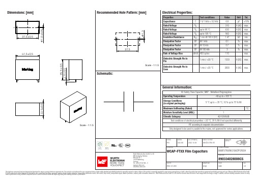
Dimensions: [mm]Scale - 1:1.5MXXP375685K310ACPP25004890334028008CSMXXP375685K310ACPP25004 890334028008CSMXXP375685K310ACPP25004 890334028008CSMXXP375685K310ACPP25004 890334028008CSMXXP375685K310ACPP25004 890334028008CST e m p e r a t u r eT T T MXXP375685K310ACPP25004890334028008CSCautions and Warnings:The following conditions apply to all goods within the product series of Film Capacitors of Würth Elektronik eiSos GmbH & Co. KG:General:•This electronic component is designed and manufactured for use in general electronic equipment.•Würth Elektronik must be asked for a written approval (following the certain PPAP level procedure) before incorporating the components into any equipment in the field such as military, aerospace, aviation, nuclear control, submarine, transportation (automotive control, train control, ship control), transportation signal, disaster prevention, medical, public information network etc. where higher safety and reliability are especially required and/or if there is the possibility of direct damage or human injury.•Electronic components that will be used in safety-critical or high-reliability applications, should be pre-evaluated by the customer. •Direct mechanical impact to the product shall be prevented as material of the body, pins or termination could flake or in the worst case it could break.•Avoid any water or heavy dust on capacitors surface, which may cause electrical leakage, damage, overheating or corrosion.•Würth Elektronik products are qualified according to international standards, which are listed in each product reliability report. Würth Elektronik does not warrant any customer qualified product characteristic, beyond Würth Elektronik specifications, for its validity and sustainability over time.•The customer is responsible for the functionality of his or her own products. All technical specifications for standard products also apply to customer specific products.•The component is designed and manufactured to be used within the datasheet specified values. If the usage and operation conditions specified in the datasheet are not met, the body, pins or termination may be damaged or dissolved.•Do not apply any kind of flexural or compressive force onto soldered or unsoldered component.•The capacitance tolerance as specified within the datasheet is only valid on the date of delivery and according specified measurement criteria.Product specificStorage conditions• A storage of Würth Elektronik products for longer than 12 months is not recommended. Within other effects, the terminals may suffer degradation, resulting in bad solderability. Therefore, all products shall be used within the period of 12 months based on the day of shipment.•Do not expose the components into direct sunlight.•The storage condition in the original packaging is defined according to DIN EN 61760-2.•The environment in which the capacitors are operated and stored has to have atmospheric characteristics and must be free of dew condensation and toxic gases (e.g. chlorine, ammonia, sulfur, hydrogen sulphide and hydrogen sulfate).•Do not expose the capacitor to environments with hazardous gas, ozone, ultraviolet rays or any kind of radiation. Avoid any contact of the capacitor with direct sunshine, saltwater, spray of water or types of oil during storage. •The storage conditions stated in the original packaging apply to the storage time and not to the transportation time of the components. Operating climatic conditions•Do not exceed the lower nor the upper specified temperature under no circumstances.•Do not use the capacitors under high humidity, high temperature or under high or low atmospheric pressure which may affect capacitors reliability.•Surface temperature including self-heating must be kept below the maximum operating temperature.Operating load conditions•Due to self-heating the reliability of the capacitor may be reduced, if high frequency AC or pulse is applied.•Consider carefully possible specific changes of electrical characteristics like capacitance over temperature, voltage and time as well as the specific performance over frequency for the actual use conditions.•Avoid any overvoltage and do not apply a continuous overvoltage. If an overvoltage is applied to the capacitor, the leakage current can increase drastically. The applied working voltage is not allowed to exceed the rated working voltage of the specific capacitor.•If film capacitors with safety approvals are operated with a DC voltage exceeding the specified AC voltage, the approvals given on the basis of IEC 60384-14 are no longer valid.Packaging:•The packaging specifications apply only to purchase orders comprising whole packaging units. If the ordered quantity exceeds or is lower than the specified packaging unit, packaging in accordance with the packaging specifications cannot be ensured. Soldering•The solder profile must comply with the Würth Elektronik technical soldering specification. All other profiles will void the warranty. •All other soldering methods are at the customer’s own risk.•Strong forces which may affect the coplanarity of the component’s electrical connection with the PCB (i.e. pins), can damage the part, resulting in void of the warranty.•Customer needs to ensure that the applied solder paste, the paste thickness and solder conditions are enough to guarantee a sufficient solder result according to the relevant criteria of IPC-A-610.•Excessive amount of solder may lead to higher tensile force and chip cracking. Insufficient amount of solder may detach the capacitor due to defective contacts.•Do not use excessive nor insufficient flux.Cleaning•Do not use any other cleaning solvents for box-typed capacitors except: ethanol, isopropanol, n-propanol - water mixtures. After cleaning a drying process with temperatures not exceeding 65°C and not longer than 4 hours is mandatory to prevent any kind ofelectrical damage.Würth Elektronik eiSos GmbH & Co. KGEMC & Inductive SolutionsMax-Eyth-Str. 174638 WaldenburgGermanyCHECKED REVISION DATE (YYYY-MM-DD)GENERAL TOLERANCE PROJECTIONMETHODFPu003.0002022-10-08DIN ISO 2768-1mDESCRIPTION TECHNICAL REFERENCEWCAP-FTXX Film Capacitors MXXP375685K310ACPP25004ORDER CODE890334028008CSSIZE/TYPE BUSINESS UNIT STATUS PAGECoating, molding and potting of the PCB•If the product is potted in the costumer’s application, the potting material might shrink or expand during and after hardening. Shrinking could lead to an incomplete seal, allowing contaminants into the body and termination. Expansion could damage the body or termination. We recommend a manual inspection after potting to avoid these effects.•If final assemblies will be placed completely in any plastic resin, physical, chemical and thermal influences must be considered. •When coating and molding the PCB, verify the quality influence on the capacitor.•Verify the curing temperature and assure that there is no harmful decomposing or reaction gas emission during curing. •Do not exceed the specified max. self-heating.Vibration resistance•Do not exceed the vibration limits given by IEC60068-2-6.Handling•After soldering, please pay attention not to bend, twist or distort the PCB in handling and storage. •Avoid excessive pressure during the functional check of the PCB. •Avoid bending stress while breaking the PCB.•WCAP-FTXX and WCAP-FTX2 capacitors are not designed and not recommended to be used in series connection to the mains. •The temperature rise of the component must be taken into consideration. The operating temperature is comprised of ambient temperature and temperature rise of the component.The operating temperature of the component shall not exceed the maximum temperature specified.Flammability•Avoid any external energy or open fire (passive flammability).These cautions and warnings comply with the state of the scientific and technical knowledge and are believed to be accurate and reliable.However, no responsibility is assumed for inaccuracies or incompleteness.(V2.2)Würth Elektronik eiSos GmbH & Co. KG EMC & Inductive Solutions Max-Eyth-Str. 174638 Waldenburg GermanyCHECKED REVISION DATE (YYYY-MM-DD)GENERAL TOLERANCEPROJECTION METHODFPu003.0002022-10-08DIN ISO 2768-1mDESCRIPTIONTECHNICAL REFERENCEWCAP-FTXX Film CapacitorsMXXP375685K310ACPP25004ORDER CODE890334028008CSSIZE/TYPEBUSINESS UNITSTATUSPAGEImportant NotesThe following conditions apply to all goods within the product range of Würth Elektronik eiSos GmbH & Co. KG:1. General Customer ResponsibilitySome goods within the product range of Würth Elektronik eiSos GmbH & Co. KG contain statements regarding general suitability for certain application areas. These statements about suitability are based on our knowledge and experience of typical requirements concerning the areas, serve as general guidance and cannot be estimated as binding statements about the suitability for a customer application. The responsibility for the applicability and use in a particular customer design is always solely within the authority of the customer. Due to this fact it is up to the customer to evaluate, where appropriate to investigate and decide whether the device with the specific product characteristics described in the product specification is valid and suitable for the respective customer application or not.2. Customer Responsibility related to Specific, in particular Safety-Relevant ApplicationsIt has to be clearly pointed out that the possibility of a malfunction of electronic components or failure before the end of the usual lifetime cannot be completely eliminated in the current state of the art, even if the products are operated within the range of the specifications.In certain customer applications requiring a very high level of safety and especially in customer applications in which the malfunction or failure of an electronic component could endanger human life or health it must be ensured by most advanced technological aid of suitable design of the customer application that no injury or damage is caused to third parties in the event of malfunction or failure of an electronic component. Therefore, customer is cautioned to verify that data sheets are current before placing orders. The current data sheets can be downloaded at .3. Best Care and AttentionAny product-specific notes, cautions and warnings must be strictly observed. Any disregard will result in the loss of warranty.4. Customer Support for Product SpecificationsSome products within the product range may contain substances which are subject to restrictions in certain jurisdictions in order to serve specific technical requirements. Necessary information is available on request. In this case the field sales engineer or the internal sales person in charge should be contacted who will be happy to support in this matter.5. Product R&DDue to constant product improvement product specifications may change from time to time. As a standard reporting procedure of the Product Change Notification (PCN) according to the JEDEC-Standard inform about minor and major changes. In case of further queries regarding the PCN, the field sales engineer or the internal sales person in charge should be contacted. The basic responsibility of the customer as per Section 1 and 2 remains unaffected.6. Product Life CycleDue to technical progress and economical evaluation we also reserve the right to discontinue production and delivery of products. As a standard reporting procedure of the Product Termination Notification (PTN) according to the JEDEC-Standard we will inform at an early stage about inevitable product discontinuance. According to this we cannot guarantee that all products within our product range will always be available. Therefore it needs to be verified with the field sales engineer or the internal sales person in charge about the current product availability expectancy before or when the product for application design-in disposal is considered. The approach named above does not apply in the case of individual agreements deviating from the foregoing for customer-specific products.7. Property RightsAll the rights for contractual products produced by Würth Elektronik eiSos GmbH & Co. KG on the basis of ideas, development contracts as well as models or templates that are subject to copyright, patent or commercial protection supplied to the customer will remain with Würth Elektronik eiSos GmbH & Co. KG. Würth Elektronik eiSos GmbH & Co. KG does not warrant or represent that any license, either expressed or implied, is granted under any patent right, copyright, mask work right, or other intellectual property right relating to any combination, application, or process in which Würth Elektronik eiSos GmbH & Co. KG components or services are used.8. General Terms and ConditionsUnless otherwise agreed in individual contracts, all orders are subject to the current version of the “General Terms and Conditions of Würth Elektronik eiSos Group”, last version available at .Würth Elektronik eiSos GmbH & Co. KGEMC & Inductive SolutionsMax-Eyth-Str. 174638 WaldenburgGermanyCHECKED REVISION DATE (YYYY-MM-DD)GENERAL TOLERANCE PROJECTIONMETHODFPu003.0002022-10-08DIN ISO 2768-1mDESCRIPTION TECHNICAL REFERENCEWCAP-FTXX Film Capacitors MXXP375685K310ACPP25004ORDER CODE890334028008CSSIZE/TYPE BUSINESS UNIT STATUS PAGE。
电解电容器测试方法详解

电解电容器测试方法详解1目的为了规范电解电容器来料检验及抽样计划,并促进来料质量的提高,特制定该检验规范。
2适用范围适用于本公司IQC对电解电容器来料的检验。
3准备设备、工具:所需工具及其规格型号如表一所示:表一(工具规格型号)品名规格/型号数量品名规格/型号数量调压器0V~450V/三相1台电流表UNI-T 1台万用表FLUKE-117C 1台游标卡尺mm/inch 1把电桥测试Zen tech 1台双综示波器LM620C型1台仪高低温交1台温度计1支变湿热试验箱4外观物理检测4.1首先需检查待测电容是否有正规的《产品规格说明书》,其中需包括产品名称、规格型号、安装尺寸、工艺要求、技术参数以及供应商名称、地址及其联系方式,以确保此批次产品是由正规厂商提供。
电容器上的标识应包括:商标、工作电压、标准静电容量、极性、工作温度范围。
4.2参考《产品规格说明书》的工艺参数,观察电容的外观、颜色、及其材质等参数是否与其所标注的工艺指标一致。
4.3用游标卡尺对电容的安装尺寸进行确认,确保电容的直径、高度以及引出端的直径与间距等参数在产品工艺的误差范围之内,且外观尺寸要符合本公司选用要求。
4.4 检查电容的外观,确保其外观整洁、无明显的变形、破损、裂纹、花斑、污浊、锈蚀等不良状况;且其标识清晰牢固、正确完整。
4.5检查其引出端子,保证其端子端正、无氧化、无锈蚀、无影响其导电性能等状况,且引出端子无扭曲、变形和影响插拔的机械损伤。
4.6 检查电解电容标注的生产日期不应超过半年,并作好记录。
5容量与损耗测试5.1用电桥测试其实际容量与标称容量是否一致(电解电容一般会有±20%的误差范围),其损耗角正切值tanθ(即D值)大小是否符合国家标准(电解电容器tanθ≤0.25)。
5.2对Zen tech电桥测试仪的使用方法:正确连接电源以后,按“POWER”键开启测试仪的工作电压;按“LCR”键选择测试类型(L:电感,C:电容,R:电阻)。