FD系列安装操作手册说明书 新
分子泵控制器FD

4、使用方法: ......................................................................................................................................16
5、故障代码 ..........................................................................................................................................17
6、常见故障处理 ..................................................................................................................................17
KYKY MODBUS 通信手册 ......................................................................................................................19
2、产品简介 ............................................................................................................................................6
2.1 产品型号及铭牌 ............................................................................................................................6 2.2 产品一览表 ....................................................................................................................................6 2.3 产品外观 ........................................................................................................................................6 2.4 FD 系列控制器与分子泵型号匹配表 ..........................................................................................8 2.5 性能指标 ........................................................................................................................................8
台大变频器FD系列使用说明书
危险 第一章 安全信息为了确保您的人身、设备及财产安全,在使用变频器之前,请务必仔细阅读本章内容,并在以后的搬运、安装、运行、调试与检修过程中遵照执行。
手册中有关安全的注意事项分类成“危险”和“警告”。
1.1 安全定义本符号提示若不按要求操作,可能导致人生伤亡或严重的财产损失。
本符号提示如果不按要求操作,可能使身体受伤或设备损坏。
在某些场合,不按要求操作,即使是违反“警告”,也会导致重大的事故。
所以在任何情况下都要遵守这些重要的注意事项。
1.2 安装注意事项◆ 请将变频器安装在金属等不可燃物体上,以免火灾的发生。
◆ 请将易燃物远离变频器,否则有发生火灾的危险。
◆ 不要将变频器安装在易燃易爆的环境中,否则有爆炸的危险。
◆ 严禁私自拆装、改装变频器,否则后果自负。
◆ 必须由具有专业资格的技术人员进行配线作业,以免触电危险。
◆ 变频器在通电状态下,请勿打开面盖或进行配线作业。
◆ 变频器通电前必须将盖板盖好,否则有触电和爆炸的危险。
◆ 存贮时间超过2年以上的变频器,通电时应先用调压器逐渐升高电压,否则有触电或爆炸的危险。
◆ 通电情况下,不要用手触摸端子,否则有触电危险。
◆请勿用潮湿的手操作变频器,否则有触电危险。
◆断开电源十分钟后才可进行维护操作,此时电源的指示灯彻底熄灭或确认正、负母线电压(+、-)在25V以下,否则有触电危险。
◆必须由专业技术人员进行更换零件等维护操作,严禁将导线或螺钉等金属物遗留在机器内,否则有发生火灾的危险。
◆对于变频器更换控制板后,必须正确设置相关参数,然后才可运行。
◆严禁将变频器的输出端子U、V、W连接至AC电源。
▲搬运时不要让操作面板和盖板受力,否则变频器局部脱落有受伤或损坏财物的危险。
▲安装应在能承受变频器重量的地方进行。
▲应避免将变频器安装在可能产生水滴飞溅的场合,否则有损坏财物的危险。
▲不允许有异物掉进变频器中。
▲变频器的接地端子必须良好接地。
▲在通电运行或断电后十分钟内严禁用手触摸散热器,以防灼伤。
FDSL 系列小型风力发电机 用户安装使用手册说明书

FDSL系列小型风力发电机用户安装使用手册FDSL series small wind generators User installationmanual2致用户首先我们感谢您购买、使用我公司生产的小型风力发电机,并为能向您提供产品和服务而感到自豪。
我们建议您在安装、使用FDSL系列小型风力发电机前,详细阅读本《用户安装使用手册》,以保证您更加熟悉产品、并进行正确地安装、连接及使用。
请妥善保管本《用户安装使用手册》以备将来查阅。
本《用户安装使用手册》的编制依据GB/T19068.1-2003《离网型风力发电机组第1部分:技术条件》、GB9969.1-1998《工业产品使用说明书总则》和JB/T5995-1992《工业产品使用说明书机电产品使用说明书编写规定》的有关要求。
3To consumerFirstly, we are thankful for your purchasing, using our products -the small wind generators, and we are proud of being able to provide you with the products and servicesRead this "user installation and use handbook.” carefully before you install or use the product.Please keep this "user installation using manual” properly for future reference.This handbook is based on GB/T19068.1-2003”from the nets type WTG part 1: technical conditions”, GB9969.1-1998 "industrial product manuals general "and T5995-1992 "JB/industrial product manuals electromechanical products instructions written provisions of relevant requirements.4目录致用户 (3)1 产品组成、特点和用途 (7)2产品规格 (7)3产品的使用环境 (7)4 工作原理 (9)5装箱清单 (10)6安装步骤 (11)7 接线流程 (13)8使用注意事项 (14)9特别提示 (15)10常见故障排除指南 (16)11 定期检查 (17)12特别声明 (18)13风力等级表 (19)5ContentsTo consumer (3)1 the product composition, characteristics and uses (7)2 product specification (7)3 Product use environment (7)4 Working principle (9)5 Packing list (10)6 Installation steps (11)7 Wiring process (13)8 using cautions (14)9 Special hints (15)10 Common trouble shooting guides (16)11 Regular inspection (17)12 Especially declare (18)13 Wind rating table (19)6SLM型水平轴小型风力发电机用户安装使用手册1产品组成、特点和用途FDSL系列小型风力发电机是一种水平轴风力发电机,主要由风叶、永磁式发电机、集流转向装置、尾翼连杆和尾翼、整流桥、控制器、逆变器等部分组成,适合在风力资源较好、市电保证不便的地区或场合使用,如海岛、边防哨所、牧场、农场、通讯基站、风光互补、野外作业等,根据风力资源的情况可以部分或完全取代市电,满足在其额定输出功率范围内各种用电器的用电要求,具有工作噪声低、使用免维护、可靠性高、安装架设方便、工作寿命长等特点。
FD烘箱中文操作手册

Binder FD系列热风循环烘箱操作手册一、安装1.电源220V 10%,50/60Hz2.须将原配插头更换为国内标准三脚接地插头,或是在仪器背部拉一接地或与主电源的接地线良好相连以确保仪器的良好接地。
3.接上电源即可。
按以下说明指导使用。
二、操作:1、温度设置警告:可燃或爆炸性物质不得放入箱内(1)按下X/W键*显示“SP”约1秒*然后变为输入值(2)用“∨”“∧”键设置所需温度*FD热风循环烘箱的温度范围为:室温以上5℃—300℃(3)选定所需温度,显示约2秒后,仪器默认该值为设定值*也可按键(持续5秒)储存设定值(4)按X/W键返回实际温度显示(或60秒后自动返回)2、定时器操作功能介绍控制器定时器有三种工作状态:计时操作、计时终止和持续工作按键,显示屏上做如下显示:显示屏显示该图标2秒后从“t1”转变为相关的工作模式显示:计时操作:开始加热,风扇转动,直至达到设定时间。
显示屏显示为:例:约2秒后,仪器默认该值为设定值按键返回实际值显示(或60秒后自动返回)。
显示屏右下角闪烁表明加热正在进行:计时终止:加热和通风均停止工作显示屏显示:在显示实际值的情况下,仪器停止工作时显示如下:持续工作:无论时间如何设定,加热和风扇均持续进行工作。
显示屏显示:持续工作模式下,加热和通风持续工作,直至操作模式改变。
3、设置加温时间(1)按键,计时器显示当前工作模式,如:显示屏显示“t1”约1秒然后变为输入界面(2)按“∨”或“∧”键直至显示屏上显示:(3)用“∧”键输入所需时间(小时.分钟)例:30分钟(4)选定所需温度约2秒后,仪器默认该值为设定值*一旦输入被确认,即开始倒计时(5)按键返回实际值显示(或60秒后自动返回)*显示屏右下角闪烁,表示加热和通风正在工作*达到设置时间后,显示屏转为如下显示:4、设置持续工作(1)按键,计时器显示当前工作状态,如:*显示“t1”约1秒,然后变为输入界面(2)按“∨”键直至显示屏显示“tlnf”(无穷大)*选定所需温度约2秒后,仪器默认该值为设定值*在设定温度下将持续进行加热及通风工作,直至取消该操作4.1、取消持续工作(1)按键,显示屏显示“t1”约1秒,然后变为输入界面(2)按“∧”键,直至显示屏变为高级命令操作模式。
D+RF系列220V(带显示)说明书中文
D+RF系列220V(带显示)说明书中文本手册适用于D+R F系列智能型电动执行机构的安装、调试、使用和维护指导。
警告:调试过程中进行全开/全关位置设置时,在接近阀门的全开或全关位置时,应该为手轮操作,严禁使用点动按钮进行点动操作,否则可能由于位置走过引起阀门或者执行器的损坏,由于此种原因造成执行器损坏,D+R概不负责。
警告:在安装、调试、使用和维护D+R F系列智能型电动执行机构前,必须仔细阅读本手册,严格按照安全操作规程操作,以防造成人身安全事故。
警告:在操作过程中,必须小心高温、高压、易燃、易爆、有毒及腐蚀性介质和高电压、强大外力等危险情况。
警告:必须严格按照规范、图纸和手册等的要求进行正确的安装、接线、调试、使用、储存和维护,否则有可能导致严重伤害、损坏设备。
目录1运输和储存 (1)2工作环境 (1)2.1环境温度 (1)2.2外壳防护等级 (2)3执行器安装 (2)3.1安装位置 (2)3.2直行程联接 (2)3.3角行程联接 (3)4电气连接和调试 (5)4.1接线端子排—10端子 (5)4.2400V AC13端子接线端子 (7)5调试 (9)5.1显示状态 (9)5.2三相接入电源的相序检测 (10)5.3进入设置状态 (11)5.4过流保护设定 (11)5.5全开位置设定 (12)5.6全关位置设置 (13)5.7信号故障位置设定 (14)5.8输入信号4M A校准 (14)5.9输入信号20M A校准 (15)5.10反馈信号4M A校准 (15)5.11反馈信号20M A校准 (16)5.12死区值设定 (16)5.13正反作用选择 (17)5.14保存/恢复设置 (18)6设备维护、保养 (19)6.1设备维护周期 (19)6.2润滑 (19)7故障信息及处理一览表 (20)11 运输和储存运输过程中执行机构的外包装可采用木箱、高强度纸箱等,内部应填充发泡物。
执行器在箱内摆放,手轮不能朝下,不能承受来自任何方向得压力,以免造成设备损坏或划伤。
FD33系列中文说明书5

FOLANNIC—UPS FD系列10-160KV A不间断电源安装使用手册FOLANNIC UPS中国技术服务中心一、前言非常感谢您对我们FOLANNIC不间断电源的信任!FOLANNIC 不间断电源是采用数字技术、IGBT(逆变功率管)技术能极大地满足您的重要设备在复杂环境中对于电源的要求…三、FOLANNIC FD31/FD33 UPS的构成及用途FOLANNIC FD31/FD33 UPS系工业级不间断电源,正常运行时会供给负载一个稳定、连续的交流电源。
在输入电提供时,UPS给电池组充电并输出稳定、可靠的交流电源;在输入电停电或波动(即各种电源污染)时,UPS由电池组放电并输出稳定、可靠的电源。
此中文安装操作手册仅适用于FD31/FD33系列UPS,此中文安装操作手册适用的容量范围为10KV A-160KV A。
FD31/FD33系列UPS 是由三相整流器、逆变器、充电器、静态开关、输出隔离变压器、电池组及控制部分组成,FD31系列UPS适用的容量范围为10KV A-60KV A。
FD33系列UPS适用的容量范围为10KV A-160KV A。
目录第一章工作原理介绍……………………..…………………………………..1.1 简介………………………………………………………………………………...1.2 工作原理……………………………………………………………….……………1.3 工作模式……………………………………………………………………………...1.4 基本功能……………………………………………………………….……………1.5 性能指标……………………………………………………………….……………第二章机柜安装……………………………………………………………...2.1环境温度……………………………………………………………………………...2.2卸货开箱……………………………………………………………………………....2.3 结构尺寸及说明……………………………………………………………………...2.4 安装固定……………………………………………………………………………...2.5进出线方式…………………………………………………………………………….2.6机柜布置…………………………………………………………………………... 第三章电气安装……………………………………………………………….3.1 电气电路图…………………………………………………………………………...3.2电缆载流量参数………………………………………………………………………3.3功率电缆………………………………………………………………………………3.4信号电缆……………………………………………………………………………….3.5并机系统安装………………………………………………………………………….3.6电池容量……………………………………………………………………………….3.7通信接口………………………………………………………………………………3.7用户设备容量的估算…………………………………………………………………第四章选件说明4.1蓄电池组…………………………………………………………….…………………4.2 蓄电池柜……………………………………………………………………………...4.3 SNMP卡………………………………………………………………………………4.4 网络软件……………………………………………………………………………...4.5 C级防雷系统………………………………………………………………... ……...4.6 电池检测模块 (4)4 45 9 101010 10 13151617 19191920202122 22 2425 252526 26 26第五章开关机的操作…………………………………………………………..1.单机启动操作步骤…………………………………………………………….2.单机的关机操作步骤………………………………………………………….. 3.并机系统的启动步骤………………………………………………………….4. 并机系统的关机步骤…………………………………………………………5. 并机系统紧急关机步骤………………………………………………………. 6.一台UPS在工作,热并入另一台UPS的操作步骤……………………………7.在并机运行状态有一台故障UPS时,关闭该UPS的操作步骤………………….第六章面板使用操作………………………………………….……………...6.1 主控屏幕……………………………………………………………………………...6.2怎样观察实时管理测量………………………………………………………………6.3怎样观测整流器实时状态……………………………………………………………6.4怎样查看逆变器实时状态……………………………………………………………6.5怎样查看自动旁路状态………………………………………………………………6.6怎样查看手动旁路状态………………………………………………………………6.7怎样进行系统管理操作……………………………………………………………...6.8怎样查看系统状态通信记录…….…………………………………………………..6.9怎样查看系统状态整机温度…….…………………………………………………..6.10怎样进行逆变、旁路转换操作………………………………………………………6.11怎样对系统功能设置……………………………………………………………... 28 28282929303031313233 36383940 40 424243第一章 工作原理介绍1.1简介FOLANNIC FD31/FD33系列UPS 系工业级不间断电源,是为重要负载提供不受电网干扰、稳压、稳频的电力供应的电源设备,在市电掉电后,UPS 可给负载继续提供一段时间供电,此系列UPS 采用带输出隔离变压器的高频双变换结构和先进的全数字控制技术,输出稳定、洁净、不间断具备完备的网络管理功能。
FD9 Serie Firesafe 全端球管值安装与维护说明书

Brief IntroductionSplit body (2-piece) valve allows easy replacement of gasket, seal, and seats without special tools. Series 90D ball valves use “floating ball” design. Induced by the line pressure the ball is free to move horizontally inside the valve body. The valve is capable of tight shutoff with flow in either direction or dead-end, regardless of the position of the valve in the line. The downstream seat, opposite the pressurized side of a closed valve, carries the load exerted by the line pressure on the ball, while the upstream seat is subject to little load or wear. For this reason, it is sometimes possible to increase seat life by turning the valve end-for-end in the pipeline.1. USE:1.1 Life of valve can be maximized if the valve is used within the rated range, in accordance with pressure, temperature,and corrosion data.2. MANUAL OPERATION:2.1 To open or close the valve, turn the handle ¼ turn (90 degrees).A. Valve in Open Position – the handle is in parallel (in-line) with the valve or pipeline.B. Valve in Closed Position – the handle is perpendicular (crossed) with the valve or pipeline.3. AUTOMATED OPERATION:3.1 Valves with actuators should be checked for valve stem alignment. Angular or linear misalignment will result in highoperational torque and unnecessary wear on the stem seal.4. GENERAL INFORMATION FOR ON-SITE INSTALLATION: 4.1 The valve may be fitted in any position on the pipeline.4.2 To prevent damage to the seats and ball surface, the pipeline must be flushed, free of dirt, burrs, and weldingresidues before installing the valve.5. DISASSEMBLING & CLEANING THE VALVE:5.1 If the valve has been used in hazardous media, it must be decontaminated before disassembly.5.2 As shipped from the factory, valves contain silicone-based lubricant. If silicone is unacceptable for your particularapplication, you may disassemble the valve and wash the parts in solvent.6. REPLACING THE THRUST WASHER AND PACKING6.1 Before replacing the thrust washer and the packing, the pipeline must be de-pressurized.Note: Stem seal leakage may be corrected without replacing the seal and/or packing. Tighten the packing nut toflatten the belleville washers. If leakage continues or valve’ s operating torque becomes excessive, the seals are worn and must be replaced.A. Remove flange bolts and nuts and lift the valve from the line. Care should be taken to avoid scratching ordamaging serrated gasket. The valves are heavy, and they should be adequately supported before removing it from the line.B. Loosen the stem nut and remove handle and stop plate. Next, remove lock saddle, packing nuts, bellevillewashers and gland.C. Remove body bolt nuts, using proper wrench. Lift off body end. One seat should come out with the body end.D. Remove body seal.E. To take out the ball, rotate stem so ball is in fully closed position. Lift ball from the body, using a strap and liftdevice, if necessary. Extreme caution should be taken to avoid damage to the ball. F. Take out the other seat.G. Stem must be removed from inside the body. A tap to the top of the stem should loosen it. The thrust washershould come out with the stem. Then, remove the stem packing.7. VISUAL INSPECTION:7.1 Clean and inspect metal parts. It is not necessary to replace neither ball nor stem unless the surface has signs ofabrasion or corrosion. We strongly recommend replacement of all soft parts whenever the valve is disassembled for reconditioning. We provide replacement kits that contain all the replaceable parts.Note: The valve may be assembled and operated dry with any lubricant. However, a light lubrication will aid inassembly and reduce initial operating torque. Lubricant used must be acceptable with the intended line fluid.8. ASSEMBLYInstall one seat in the body cavity with the spherical curvature facing the ball.8.1 Install the thrust washer on stem and slide the stem up through the body. Install packing, gland, belleville washers,locking saddle. Screw the packing nut into the stem. Lock the saddle in place.8.3 Install stop plate, handle and washer. Screw the stem nut into the stem until the handle is secure.8.4 Turn handle to the closed position. Line up the ball slot with the stem end and slide the ball into position. Turn thehandle to the open position to hold the ball in place. 8.5 Install the remaining seat into body side.8.6 Put body seal gasket into body and line up end flange. Because the body flange bolt pattern is different from the lineflange bolt pattern, it is possible to assemble the valve such that the line flanges bolt pattern don’ t line up. Be certain to align end flanges bolt holes to straddle valve center lines. Be careful not to damage body seal when putting cap end into body.8.8 Install cap end nuts and tighten in the “star” pattern to the proper torque. Extreme care must be exercised duringadjustment of cap end nuts to make sure that complete engagement of the studs with body flange is maintained. There should be at least one stud thread exposed on each side.8.9 Cycle the valve slowly, with a gentle back and forth motion, to build gradually to the full quarter turn. By cyclingslowly, the seat lips will assume a permanent seal shape against the ball. A fast turning motion, at this point, may cut the seats before they have a chance to form the proper seal.8.10 Test valve, if possible, prior to placing valve back into line position. If not properly secured, the valve can separatefrom the pressure source, resulting in possible injury. Always join the valve to companion flanges of same pressure rating as valve and secure with a full set of flange bolts.TEST AS FOLLOWS:A. Secure valve to a test fixture by means of a mating flange with full bolting and a suitable gasket. Orient valve soseat to be tested is facing up.B. Introduce 50 to 100 psig air. Partially cycle the valve, under pressure, then slowly close to make sure the cavity ispressurized (use hearing protection). Pour water into the upper port to cover the ball and visually check for bubbles. If bubbles appear, pour the water out, cycle the valve several times and recheck. To check for leakage in the other port, reverse the valve and introduce air pressure to the port just checked.C. Check stem seal at this time by coating the stem top area with a water/soap solution. If leakage occurs, tighten stemseal just until leakage stops.Valve SizeBreak Away Torque(In-lbs.)Torque of Body Bolts(In-lbs.)Torque of Stem Nut(In-lbs.)150# Flange300# Flange½” 110 125 174 ~ 200 130 ¾” 140 175 200 ~ 217 130 1” 175 220 260 ~ 286 130 1-1/2” 400 450 286 ~ 304 208 2” 450 525 347 ~ 391 208 2-1/2” 620 750 347 ~ 391 208 3” 1000 1400 477 ~ 521 304 4” 1600 1900 477 ~ 521 304 6”27003050477 ~ 521391A-T Controls product, when properly selected, is designed to perform its intended function safely during its useful life. However, the purchaser or user of A-T Controls products should be aware that A-T Controls products might be used in numerous applications under a wide variety of industrial service conditions. Although A-T Controls can provide general guidelines, it cannot provide specific data and warnings for all possible applications. The purchaser / user must therefore assume the ultimate responsibility for the proper sizing and selection, installation, operation, and maintenance of A-T Controls products. The user should read and understand the installation operation maintenance (IOM) instructions included with the product, and train its employees and contractors in the safe use of A-T Controls products in connection with the specific application.While the information and specifications contained in this literature are believed to be accurate, they are supplied for informative purposes only. Because A-T Controls is continually improving and upgrading its product design, the specifications, dimensions and information contained in this literature are subject to change without notice. Should any question arise concerning these specifications, the purchaser/user should contact A-T Controls.For product specifications go to /A-T Controls, Inc. • 9955 International Boulevard, Cincinnati, OH 45246 • Phone: (513) 530-5175 • Fax: (513) 247-5462 • 。
FD系列电源分配箱说明书
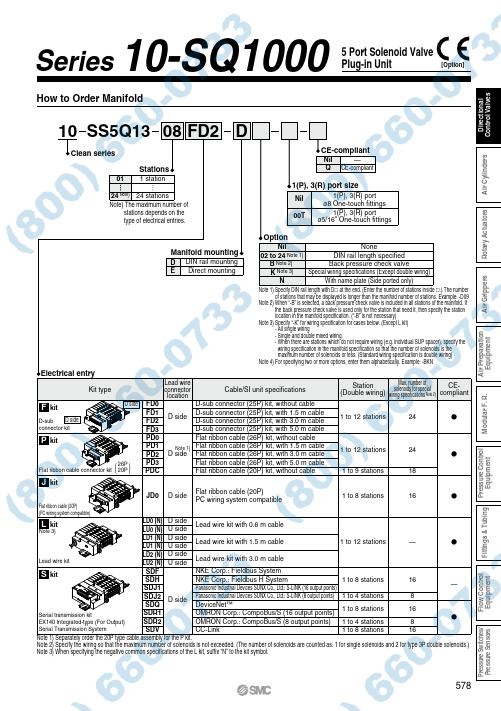
FD20124 Note) 1 station 24 stationsSS5Q1308StationsElectrical entryOptionDManifold mountingD EDIN rail mounting Direct mounting……1(P), 3(R) port sizeNil 1(P), 3(R) port ø8 One-touch fittings 1(P), 3(R) portø5/16" One-touch fittingsCE-compliantNil Q—CE-compliantKit typeFD0FD1FD2FD3PD0PD1PD2PD3PDCJD0LD0 (N)LU0 (N)LD1 (N)LU1 (N)LD2 (N)LU2 (N)SDF SDH SDJ1SDJ2SDQ SDR1SDR2SDVD side D side D sideD sideD side U side D side U side D side U sideCable/SI unit specificationsLead wire kit with 0.6 m cable Lead wire kit with 1.5 m cable Lead wire kit with 3.0 m cableFlat ribbon cable (20P)PC wiring system compatibleD-sub connector (25P) kit, without cable D-sub connector (25P) kit, with 1.5 m cable D-sub connector (25P) kit, with 3.0 m cable D-sub connector (25P) kit, with 5.0 m cable Flat ribbon cable (26P) kit, without cable Flat ribbon cable (26P) kit, with 1.5 m cable Flat ribbon cable (26P) kit, with 3.0 m cable Flat ribbon cable (26P) kit, with 5.0 m cable Flat ribbon cable (20P) kit, without cable NKE Corp.: Fieldbus System NKE Corp.: Fieldbus H SystemPanasonic Industrial Devices SUNX Co., Ltd.: S-LINK (16 output points)Panasonic Industrial Devices SUNX Co., Ltd.: S-LINK (8 output points)DeviceNet ™OMRON Corp.: CompoBus/S (16 output points)OMRON Corp.: CompoBus/S (8 output points)CC-Link1 to 12 stations 1 to 12 stations 1 to 9 stations 1 to 8 stations1 to 12 stations1 to 8 stations 1 to 4 stations 1 to 8 stations 1 to 4 stations 1 to 8 stationsStation (Double wiring)Lead wire connector location24241816—16816816Max. number of solenoids for specialwiring specifications Note 2)—CE-compliantFP JLSNote 1) Specify DIN rail length with D at the end. (Enter the number of stations inside .) The numberof stations that may be displayed is longer than the manifold number of stations. Example: -D09Note 2) When “-B” is selected, a back pressure check valve is included in all stations of the manifold. Ifthe back pressure check valve is used only for the station that need it, then specify the station location in the manifold specification. (“-B” is not necessary)Note 3) Specify “-K” for wiring specification for cases below. (Except L kit)- All single wiring- Single and double mixed wiring.- When there are stations which do not require wiring (e.g. individual SUP spacer), specify the wiring specification in the manifold specification so that the number of solenoids is the maximum number of solenoids or less. (Standard wiring specification is double wiring)Note 4) For specifying two or more options, enter them alphabetically. Example: -BKN00TNil 02 to 24 Note 1)B Note 2)K Note 3)NNoneDIN rail length specified Back pressure check valve Special wiring specifications (Except double wiring)With name plate (Side ported only)Note) The maximum number ofstations depends on the type of electrical entries.kitLead wire kitFlat ribbon cable (20P)(PC wiring system compatible)Serial transmission kitEX140 Integrated-type (For Output) Serial Transmission SystemD-subconnector kitkitkitkitkitU sideD side Flat ribbon cable connector kit26P 20P( )Note 1) Separately order the 20P type cable assembly for the P kit.Note 2) Specify the wiring so that the maximum number of solenoids is not exceeded. (The number of solenoids are counted as: 1 for single solenoids and 2 for type 3P double solenoids.)Note 3) When specifying the negative common specifications of the L kit, suffix “N” to the kit symbol.Note 3)5 Port Solenoid Valve Plug-in UnitS eries 10-SQ1000How to Order Manifold10Clean seriesNote 1)[Option]578A i r P r e p a r a t i o n E q u i p m e n tP r e s s u r e C o n t r o l E q u i p m e n tF l o w C o n t r o l E q u i p m e n tP r e s s u r e S w i t c h e s /P r e s s u r e S e n s o r sD i r e c t i o n a l C o n t r o l V a l v e sA i r G r i p p e r s M o d u l a r F . R .F i t t i n g s & T u b i n gA i r C y l i n d e r sR o t a r y A c t u a t o r s。
- 1、下载文档前请自行甄别文档内容的完整性,平台不提供额外的编辑、内容补充、找答案等附加服务。
- 2、"仅部分预览"的文档,不可在线预览部分如存在完整性等问题,可反馈申请退款(可完整预览的文档不适用该条件!)。
- 3、如文档侵犯您的权益,请联系客服反馈,我们会尽快为您处理(人工客服工作时间:9:00-18:30)。
升饮料。
注意:主机箱不得倒置或斜置。
5
故障
由于使用不当或机组其他原因, 在使用过程中会产生一些故障。当机 组发生故障时请先阅读《说明书》,找 出故障,按故障排除一览表的故障等
级进行处理。在未明确故障及故障等 级前不得进行维修,如通过故障排除 一览表无法确定故障和故障等级的, 请与我公司市场服务部联系。
速 度
温差(℃)
工况 D(分钟) 约 350
约 100 ≤1.5 约 120 ≤1.5 约 160 ≤1.5 约 350
约 100 ≤2.5 约 120 ≤2.5 约 160 ≤2.5 约 360
约 100 ≤1.5 约 150 ≤1.5 约 250 ≤1.5 约 350
约 100 ≤3.5 约 150 ≤3.5 约 320 ≤3.5 约 400
浓度的次氯酸盐消毒液或等
替换。
效量,让搅拌电机运转 3 分钟,
3) 定期清洗不锈钢冷却底盘。
使消毒液在槽内喷流或搅拌。
4) 保持机组面板的整洁,定期除
4) 在每次清洗中,完全彻底的排
去冷凝器上的灰尘(如在拆下
去消毒液,尤其是残留在不锈
面板后,用吹风机吹或等效办
钢冷却底盘凹槽中的消毒液
法)。
(可将组件拆散,分件清洗, 再组装。该过程应注意卫生),
FD-084 电路图
英文 L GND N K COMP
中文 相线 地线 零线 开关 压缩机
电路图中英文对照
英文 C-T C Mspray Mfan
中文 温控器 运转电容 搅拌电机 冷凝风机
“KFC”用 FD-084 果汁机安装使用注意事项(如下图):
1) 果汁槽内饮料最少不得小于 2 升。 2) 四槽放置不同糖粘度饮料时建议 2、3 槽放置果汁类饮料,1、4 槽放置茶、
技术参数
项目
机型 FD-051
FD-102
FD-153
FD-042
FD-084
外型(长 X 宽 X 高 mm) 250X390X700 440X390X700 650X390X700 286X440X650 521X390X650
净重(Kg)
19.5
31.5
39.5
24.5
36.0
适用电源
220V/50Hz 1P
汁机的工作环境温度≥35℃,
锈钢冷却底盘、轴承套和叶轮
温控器调节位置应调至中点
也洗净擦干,最后将机组组装
偏上)。
好(仍将轴承套和叶轮装在轴
3) 先开搅拌开关,观察果汁喷流
心销上)。
状况或搅拌状况是否良好。 4) 打开制冷机组开关。
4) 套上干净的塑料袋,装入主机
注意:必须保持果汁槽内至少有 2
箱中。
使用与保养 ------------------------------------------------------- 5
故障 ------------------------------------------------------------- 6
附录 ------------------------------------------------------------ 8
温差(℃)
≤1.8
≤2.5
≤2.5
≤3.5
满 载
工况 A
约 120
约 120
约 120
约 120
约 120
果 汁
温差(℃)
≤1.5
≤2.0
≤1.5
≤3.5
饮 料
工况 B
约 180
约 180
约 180
约 240
约 240
降 温
温差(℃)
≤1.5
≤2.0
≤1.5
≤3.5
速 度
工况 C
约 600
约 600
上插入前面板凸缘下。 3) 将盛水盘放低,使盛水盘底部
的突出物插入悬挂插孔。
3
――――――――――――――――
图四
图三(上:普通槽、下:迷你槽)
4
使用与保养
z 使用: 当机器第一次使用或相隔一 z 日常维护和保养:
段时间再次使用均须进行清
1) 定期经常的清洗果汁槽内所
洗和消毒处理。处理步骤如
3
转
继电器故障 更换压缩机继电器
3
过载保护跳 查看是否散热不良造成过载, 1
依法排除散热不良,等五分钟
左右,压缩机会自动运转
更换压缩机过载保护开关
3
调节温控至合适位置 2
温控故障 更换温控器
3
压缩机故障 更换压缩机
4
漏冷媒
检修管路系统
4
物料出不来 阻塞
清洗相关部件
1
物料冲泡不均,重新冲泡
1
安装不良 密封圈松动 拆下重新安装
1) 将果汁槽固定板中心孔套入 轴心头。
2) 滑动果汁槽固定板,将其锁定 销插入轴心头下面。
3) 旋转果汁槽固定板 1/8 圈使其 锁定(迷你槽旋转 90°),反 转则放松。
注意:如果觉得锁紧后果汁槽固定 板很松,那表明没有正确锁 紧,必须重复上述步骤。
z 盛水盘的安装(参照图四):
1) 将盛水盘盖盖于盛水盘上。 2) 将盛水盘的突起边缘由下往
2
3
2
4
2
3
2
4
注:1)如选水泵覆盖 A,则配有喷流管;如选水泵覆盖 B,则没有喷流管。 2) FD-051/102/153 标配有喷流管,水泵覆盖 A; FD-042/084 标配水泵覆盖 B,无喷流管。
8
z 电器原理图
FD-051 电路图
FD-102 电路图 9
FD-153 电路图
FD-042 电路图 10
1) 剪断塑料捆扎带,打开包装箱 的上盖。
2) 打开纸箱,取出瓦楞纸隔板。 3) 取出果汁槽及其他附件,去掉
塑料袋和包装膜,并清点。
z 果汁槽的安装(参照图一):
1) 将果汁槽的下端圆柱外环面 和密封圈用干净的水(如纯水 等)润湿,再将果汁槽密封圈 装入果汁槽底部开口处的下 端圆柱外环面颈部。
――――――――――――――――
FOOD AND BEVERAGE SOLUTIONS
FD 系列果汁机 安装、操作与使用手册
SHANGHAI FRESER REFRIGERATION EQUIPMENT CO., LTD. 上海富申冷机有限公司
目录
技术参数 --------------------------------------------------------- 1
约 600
约 600
约 600
温差(℃)
≤1.8
≤2.2
≤2.5
≤3.5
注 1:上表的不同工况的降温速率适合使用喷流管的装置;如选用没有喷流管的装置,则速度可以更快些。 降温速度的单位为:分钟。 注 2:A 工况-环境温度为 18℃ B 工况-环境温度为 24℃ C 工况-环境温度为 32℃ D 工况-环境 温度为 40.6℃ 注 3:A、B 和 C 工况的降温速度是指最冷的一个果汁槽内果汁的温度由环温降到 5℃的时间。
1
阀柱O形圈松动 重新安装
1
密封圈不良 更换
1
其他
密封圈劣化 更换密封圈
2
阀柱O形圈劣化 更换阀柱O形圈
2
水槽破裂 更换水槽
2
水槽盖破裂 更换水槽盖
2
z 包装箱清单
附录
项目
机型 FD-051
FD-102
FD-153 FD-042 FD-084
主
机组
机组 1 台 机组 1 台 机组 1 台 机组 1 台 机组 1 台
图一(上:普通槽、下:迷你槽) 2
2) 将手放在果汁槽体顶部对角, 抓紧槽体。通过前后的转动和 向下的压力,使槽体下滑到 位。保证果汁槽的各侧面与果 汁机主机的相应侧面的平行 度,果汁槽的饮料出口应位于 盛水盘上方。
3) 将轴承套装在轴芯上,轴承套 的凸缘必须支撑在不锈钢冷 却底盘上。在轴承套上安装叶 轮,叶轮有棱面向上(一般出 厂时已安装)。
1
安装
z 基本要求:
1) 确定除果汁机外的其他有关 外围设备的安全性和完好性 (诸如:电源、插座等)。
2) 必须确保果汁机排风口与周 围物体间至少有 15 厘米的空 间。
3) 果汁机不能置于太阳光直射 的地方。
4) 果汁机须安置于平整、水平的 平台上。
5) 果汁机不能置于热风口处,并 远离热源。
z 拆去包装
6
7
冷饮机 故障排除一览表
常见故障 故障原因 原因细分 排 除 方 法
完全不动 机组没电 停电
通知电力公司
1
开关箱开关 跳脱 1 机组
1 检查线路
漏电 2 过载 2
3 2
重新插好
1
电源线断裂 更换电源线
2
开关没开
打开开关
1
其他
查修线路
3
有声音不喷
叶轮磨损 更换叶轮
2
水
其他
物料太少 加入物料
1
更换水泵覆盖
4) 在水泵覆盖 A 顶部的套筒中插 入喷流管,保证喷流管插足于 套筒中,使槽盖安装到位后不 会碰到。如用户选用水泵覆盖 B,则无此步骤。
5) 在轴心上安装水泵覆盖,注意 使喷流管正对机器前方,位于 果汁槽中央。水泵覆盖前部的 1/2″的凸缘应位于每个果汁 槽槽体内底部的两个定位点 中间。
6) 在水泵覆盖上安装果汁槽固 定板,果汁槽固定板安装在轴 心头上。果汁机启动前,必须 保证果汁槽固定板已被正确 安装(参照果汁槽固定板的安 装步骤)。
有相关零件,以保证果汁饮料
下: