华为三层交换机的配置案例
华为s3928三层交换机配置
华为S3928 三层交换机配置2008-08-04 11:06配置环境与配置文件如下:环境, 双wan口路由接入ADSL ,下接华为S3928p-SI 做核心交换机.交换机下接普通PC 和傻瓜式的TP-Link交换机, 现用可核心交换机e 1/0/24口(ip:)直接连接路由器.划分5个vlan 并隔离 e 1/0/11 to e 1/0/14端口.<Quidway>dis cur#sysname Quidway#dhcp-server 1 ip#radius scheme system#domain system#vlan 1#vlan 2description comman#vlan 3description finance#vlan 4description ap#vlan 5description server#vlan 6description route#interface Vlan-interface2ip address#interface Vlan-interface3ip address#interface Vlan-interface4ip addressdhcp-server 1#interface Vlan-interface5ip address#interface Vlan-interface6 ip address#interface Aux1/0/0#interface Ethernet1/0/1 port access vlan 2#interface Ethernet1/0/2 port access vlan 2#interface Ethernet1/0/3 port access vlan 2#interface Ethernet1/0/4 port access vlan 2#interface Ethernet1/0/5 port access vlan 2#interface Ethernet1/0/6 port access vlan 2#interface Ethernet1/0/7 port access vlan 2#interface Ethernet1/0/8 port access vlan 2#interface Ethernet1/0/9 port access vlan 2#interface Ethernet1/0/10 port access vlan 2#interface Ethernet1/0/11 port access vlan 3port isolate#interface Ethernet1/0/12 port access vlan 3port isolate#interface Ethernet1/0/13port access vlan 4port isolate#interface Ethernet1/0/14port access vlan 4port isolate#interface Ethernet1/0/15port access vlan 5#interface Ethernet1/0/16port access vlan 5#interface Ethernet1/0/17port access vlan 5#interface Ethernet1/0/18port access vlan 5#interface Ethernet1/0/19port access vlan 5#interface Ethernet1/0/20port access vlan 5#interface Ethernet1/0/21#interface Ethernet1/0/22#interface Ethernet1/0/23#interface Ethernet1/0/24port access vlan 6#interface GigabitEthernet1/1/1#interface GigabitEthernet1/1/2#interface GigabitEthernet1/1/3#interface GigabitEthernet1/1/4#undo irf-fabric authentication-mode #interface NULL0#voice vlan mac-address 0001-e300-0000 mask ffff-ff00-0000#ip route-static 0.0.0.0 preference 60#user-interface aux 0 7user-interface vty 0 4#return另需要路由器上添加回路,对应该交换机的路由规则 . 侠诺路由器支持多子网段,还需添加的子网段.。
华为三层交换机配置案例

华为三层交换机配置案例华为三层交换机配置案例下面以华三通信H3C S3600-28P-SI为例,给大家带来华为三层交换机配置案例,希望对你有帮助!配置命令system-view //进入系统视图[H3C]display current-configuration //显示当前配置//以下开始配置第一步:划分VLAN,并描述vlan 1description local-S3600vlan 2description link-to-wenquanvlan 3description link-to-ruzhouvlan 4description link-to-xiaotunvlan 5description link-to-baofengvlan 6description link-to-pingxivlan 7description link-to-pingnanvlan 8description Uplink-to-Putianvlan 9description link-to-pingxicentre第二步:给VLAN 划网关interface Vlan-interface2description link to wenquanip address 10.41.77.41 255.255.255.192 interface Vlan-interface3description link to ruzhouip address 10.41.77.105 255.255.255.192 interface Vlan-interface4description link to xiaotunip address 10.41.77.169 255.255.255.192 interface Vlan-interface5description link to baofengip address 10.41.77.233 255.255.255.192 interface Vlan-interface6description link to pingxiip address 10.41.78.41 255.255.255.192 interface Vlan-interface7description link to pingnanip address 10.41.78.105 255.255.255.192 interface Vlan-interface8description uplink to putianip address 10.41.244.102 255.255.255.252 interface Vlan-interface9description link to pingxicentreip address 10.41.80.233 255.255.255.192 第三步:给VLAN 指定端口interface Ethernet1/0/2description link to wenquanport access vlan 2interface Ethernet1/0/3description link to ruzhouport access vlan 3interface Ethernet1/0/4description link to xiaotunport access vlan 4interface Ethernet1/0/5description link to baofengport access vlan 5interface Ethernet1/0/6description link to pingxiport access vlan 6interface Ethernet1/0/7description link to pingnanport access vlan 7interface Ethernet1/0/8description uplink to putianport access vlan 8interface Ethernet1/0/9 to Ethernet1/0/24description link to pingxicentreport access vlan 9第四步:配置路由协议//(1)用RIP配动态路由ripnetwork 10.41.77.41network 10.41.77.105network 10.41.77.169network 10.41.77.233network 10.41.78.41network 10.41.78.105network 10.41.80.233network 10.41.244.102//(2)配静态路由(只用对远端设备配一条路由即可,本地自通)---推荐用此协议ip route 0.0.0.0 0.0.0.0 10.41.244.101案例:华为S3600三层交换机配置方法sys[Quidway]vlan 2[Quidway-vlan2]port e1/0/2[Quidway-vlan2]int vlan 2[Quidway-Vlan-interface2]ip add 10.41.77.41 255.255.255.192 //温泉网关[Quidway-Vlan-interface2]vlan 3[Quidway-vlan3]port e1/0/3[Quidway-vlan3]int vlan 3[Quidway-Vlan-interface3]ip add 10.41.77.105 255.255.255.192 //汝州网关[Quidway-Vlan-interface3]vlan 4[Quidway-vlan4]port e1/0/4[Quidway-vlan4]int vlan 4[Quidway-Vlan-interface4]ip add 10.41.77.169 255.255.255.192 //小屯网关[Quidway-Vlan-interface4]vlan 5[Quidway-vlan5]port e1/0/5[Quidway-vlan5]int vlan 5[Quidway-Vlan-interface5]ip add 10.41.77.233 255.255.255.192 //宝丰网关[Quidway-Vlan-interface5]vlan 6[Quidway-vlan6]port e1/0/6[Quidway-vlan6]int vlan 6[Quidway-Vlan-interface6]ip add 10.41.78.41 255.255.255.192 //平西网关[Quidway-Vlan-interface6]vlan 7[Quidway-vlan7]port e1/0/7[Quidway-vlan7]int vlan 7[Quidway-Vlan-interface7]ip add 10.41.78.105 255.255.255.192 //平南网关[Quidway-Vlan-interface7]vlan 8[Quidway-vlan8]port e1/0/8[Quidway-vlan8]int vlan 8[Quidway-Vlan-interface8]ip add 10.41.244.102 255.255.255.252 //省中心网关[Quidway-Vlan-interface8]vlan 9[Quidway-vlan9]port e1/0/9 to e1/0/24[Quidway-vlan9]int vlan 9[Quidway-Vlan-interface9]ip add 10.41.80.233 255.255.255.192 //分中心网关//配置路由ip route 0.0.0.0 0.0.0.0 10.41.244.101华为三层交换机上如何实现不同vlan间的通信命令如下:一、组网需求:交换机配置了4个VLAN,分别为VLAN1,VLAN2,VLAN3,VLAN4,要求VLAN1可以与VLAN2,3,4互访,但是VLAN2,3,4之间不能互访,用Hybrid端口属性实现此功能。
HC三层交换机配置实例

H3C三层交换机配置实例1 网络拓扑图 02 配置要求 03划分VLAN并描述 03.1进入系统视图 03.2 创建VLAN并描述 .................................................................. 错误!未定义书签。
4 给VLAN设置网关 (1)4.1 VLAN1的IP地址设置 (1)4.2 VLAN100的网关设置 (2)4.3 VLAN101的网关设置 (2)4.4 VLAN102的网关设置 (3)4.5 VLAN103的网关设置 (3)5 给VLAN指定端口,设置端口类型 (4)5.1 VLAN100指定端口 (4)5.2 VLAN102指定端口 (5)5.3 VLAN1/101/103指定端口 (5)6 配置路由协议 (6)6.1 默认路由 (6)6.2配置流分类 (7)6.3 定义行为 (7)6.4 应用QOS策略 (8)6.5 接口配置QOS策略 (8)1 网络拓扑图图1-1 网络拓扑图2 配置要求用户1网络:172.16.1.0/24 至出口1网络:172.16.100.0/24用户2网络:192.168.1.0/24 至出口2网络:192.168.100.0/24实现功能:用户1通过互联网出口1,用户2通过互联网出口2。
3划分VLAN并描述3.1进入系统视图<H3C>system-view //进入系统视图图3-1 系统视图3.2 创建VLAN并描述[H3C]vlan 1 //本交换机使用[H3C-vlan1]description Manager //描述为“Manager”[H3C-vlan1]quit[H3C]vlan 100 //划分vlan100[H3C-vlan100]description VLAN 100 //描述为“VLAN 100”[H3C-vlan100]quit[H3C]vlan 101 //划分vlan101[H3C-vlan101]description VLAN 101 //描述为“VLAN 101”[H3C-vlan101]quit[H3C]vlan 102 //划分vlan102[H3C-vlan102]description VLAN 102 //描述为“VLAN 102”[H3C-vlan102]quit[H3C]vlan 103 //划分vlan103[H3C-vlan103]description VLAN 103 //描述为“VLAN 103”[H3C-vlan103]quit[H3C]图3-2 划分VLAN及描述4 给VLAN设置网关4.1 VLAN1的IP地址设置把VLAN1的IP地址设置为192.168.0.254,子网掩码为255.255.255.0,用于本地使用。
三层交换机详细配置实例(图)
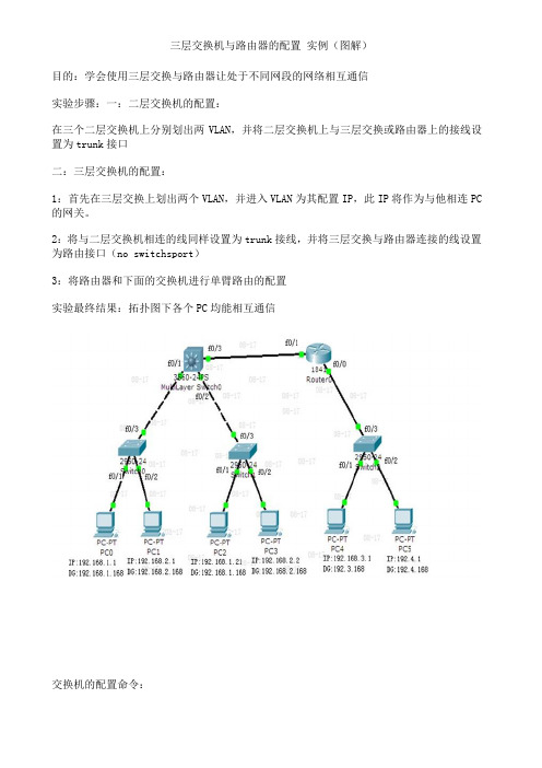
三层交换机与路由器的配置实例(图解)目的:学会使用三层交换与路由器让处于不同网段的网络相互通信实验步骤:一:二层交换机的配置:在三个二层交换机上分别划出两VLAN,并将二层交换机上与三层交换或路由器上的接线设置为trunk接口二:三层交换机的配置:1:首先在三层交换上划出两个VLAN,并进入VLAN为其配置IP,此IP将作为与他相连PC 的网关。
2:将与二层交换机相连的线同样设置为trunk接线,并将三层交换与路由器连接的线设置为路由接口(no switchsport)3:将路由器和下面的交换机进行单臂路由的配置实验最终结果:拓扑图下各个PC均能相互通信交换机的配置命令:SW 0:Switch>Switch>enSwitch#confConfiguring from terminal, memory, or network [terminal]?Enter configuration commands, one per line. End with CNTL/Z.Switch(config)#vlan 2Switch(config-vlan)#exitSwitch(config)#int f0/2Switch(config-if)#switchport access vlan 2Switch(config-if)#no shutSwitch(config-if)#int f0/3Switch(config-if)#switchport mode trunk%LINEPROTO-5-UPDOWN: Line protocol on Interface FastEthernet0/3, changed state to down%LINEPROTO-5-UPDOWN: Line protocol on Interface FastEthernet0/3, changed state to upSwitch(config-if)#exitSwitch(config)#SW 1:Switch>enSwitch#confConfiguring from terminal, memory, or network [terminal]?Enter configuration commands, one per line. End with CNTL/Z.Switch(config)#int f0/2Switch(config-if)#switchport access vlan 2% Access VLAN does not exist. Creating vlan 2Switch(config-if)#no shutSwitch(config-if)#exitSwitch(config)#int f0/3Switch(config-if)#switchport mode trunk%LINEPROTO-5-UPDOWN: Line protocol on Interface FastEthernet0/3, changed state to down%LINEPROTO-5-UPDOWN: Line protocol on Interface FastEthernet0/3, changed state to upSwitch(config-if)#SW 2:Switch>enSwitch#confConfiguring from terminal, memory, or network [terminal]?Enter configuration commands, one per line. End with CNTL/Z.Switch(config)#int f0/2Switch(config-if)#switchport access vlan 2% Access VLAN does not exist. Creating vlan 2Switch(config-if)#exitSwitch(config)#int f0/3Switch(config-if)#switchport mode trunkSwitch(config-if)#三层交换的配置命令:Switch>enSwitch#confConfiguring from terminal, memory, or network [terminal]?Enter configuration commands, one per line. End with CNTL/Z.Switch(config)#int f0/1Switch(config-if)#switchport mode trunk%LINEPROTO-5-UPDOWN: Line protocol on Interface FastEthernet0/2, changed state to downSwitch(config-if)#exitSwitch(config)#int f0/2Switch(config-if)#switchport mode trunkSwitch(config-if)#exitSwitch(config)#vlan 2Switch(config-vlan)#exitSwitch(config)#int vlan 1Switch(config-if)#no shut%LINK-5-CHANGED: Interface Vlan1, changed state to up%LINEPROTO-5-UPDOWN: Line protocol on Interface Vlan1, changed state to up Switch(config-if)#ip address 192.168.1.168 255.255.255.0Switch(config-if)#exitSwitch(config)#int vlan 2%LINK-5-CHANGED: Interface Vlan2, changed state to up%LINEPROTO-5-UPDOWN: Line protocol on Interface Vlan2, changed state to upSwitch(config-if)#ip addSwitch(config-if)#ip address 192.168.2.168 255.255.255.0Switch(config-if)#%LINK-5-CHANGED: Interface FastEthernet0/3, changed state to up%LINEPROTO-5-UPDOWN: Line protocol on Interface FastEthernet0/3, changed state to upSwitch(config-if)#exitSwitch(config)#int f0/3Switch(config-if)#no switchport%LINEPROTO-5-UPDOWN: Line protocol on Interface FastEthernet0/3, changed state to down%LINEPROTO-5-UPDOWN: Line protocol on Interface FastEthernet0/3, changed state to upSwitch(config-if)#Switch(config-if)#ip address 192.168.10.1 255.255.255.0Switch(config-if)#no shutSwitch(config-if)#exitSwitch(config)#ip routingSwitch(config-if)#exitSwitch(config)#ip route 0.0.0.0 0.0.0.0 192.168.10.2Switch(config)#路由器的配置:Router>enRouter#confConfiguring from terminal, memory, or network [terminal]?Enter configuration commands, one per line. End with CNTL/Z.Router(config)#int f0/0Router(config-if)#no shut%LINK-5-CHANGED: Interface FastEthernet0/0, changed state to upRouter(config-if)#exitRouter(config)#int f0/1Router(config-if)#no shut%LINK-5-CHANGED: Interface FastEthernet0/1, changed state to up%LINEPROTO-5-UPDOWN: Line protocol on Interface FastEthernet0/1, changed state to upRouter(config-if)#exitRouter(config)#int f0/0Router(config-if)#no shutRouter(config-if)#exitRouter(config)#int f0/0.1Router(config-subif)#encapsulation dot1Q 1Router(config-subif)#ip address 192.168.3.168 255.255.255.0Router(config-subif)#exitRouter(config)#int f0/0.2Router(config-subif)#encapsulation dot1Q 2Router(config-subif)#ip addRouter(config-subif)#ip address 192.168.4.168 255.255.255.0Router(config-subif)#exitRouter(config)#ip route 0.0.0.0 0.0.0.0 192.168.10.1Router(config)#exit%SYS-5-CONFIG_I: Configured from console by consoleRouter#confConfiguring from terminal, memory, or network [terminal]?Enter configuration commands, one per line. End with CNTL/Z.Router(config)#int f0/1Router(config-if)#ip addRouter(config-if)#ip address 192.168.10.2 255.255.255.0 Router(config-if)#。
华为三层交换机做OSPF

配置OSPF基本功能组网需求如图1所示,所有的S9300都运行OSPF,并将整个自治系统划分为3个区域,其中S9300-A和S9300-B作为ABR来转发区域之间的路由。
配置完成后,每台S9300都应学到自治系统的到所有网段的路由。
图1 OSPF基本配置组网图S9300 接口对应的VLANIF IP地址S9300-A GigabitEthernet1/0/1 VLANIF 10 192.168.0.1/24S9300-A GigabitEthernet1/0/2 VLANIF 20 192.168.1.1/24S9300-B GigabitEthernet1/0/1 VLANIF 10 192.168.0.2/24S9300-B GigabitEthernet1/0/2 VLANIF 30 192.168.2.1/24S9300-C GigabitEthernet1/0/1 VLANIF 20 192.168.1.2/24S9300-C GigabitEthernet1/0/2 VLANIF 40 172.16.1.1/24S9300-D GigabitEthernet1/0/1 VLANIF 30 192.168.2.2/24S9300-D GigabitEthernet1/0/2 VLANIF 50 172.17.1.1/24配置思路采用如下的思路配置OSPF基本功能:1.配置各接口所属VLAN ID。
2.配置各VLANIF接口的IP地址。
3.在各S9300设备上使能OSPF,指定不同区域的网段。
4.查看路由表及数据库信息。
数据准备•各接口所属的VLAN ID,具体数据如图1所示。
•各VLANIF接口的IP地址,具体数据如图1所示。
•各S9300设备的Router ID,OSPF进程号以及各接口所属的区域。
▪S9300-A的Router ID 1.1.1.1,运行的OSPF进程号1,在区域0的网段192.168.0.0/24,在区域1的网段192.168.1.0/24。
华为三层交换机配置总结
一、基本命令: (1)保存当前配置:save [ configuration-file ] (1)清除当前配置:<core s9303-1>reset saved-configuration (1)重启当前设备:<core s9303-1>reboot (1)取消单条配置:undo +要取消的配置命令 (1)[SwitchA-Ethernet0/3]undo port link-type trunk (1)显示命令: (2)配置静态路由:ip route-static 目标网段子网掩码下一跳地址 (2)设置trunk: (2)telnet登陆设置: (2)二、配置实例 (3)1.实例说明 (3)2拓扑图如下: (4)交换机名为zuo的配置:(华为5328设置) (4)9300的配置: (8)交换机you的设置:(华为5328设置) (9)4.测试 (12)(1)vrrp正常状态下测试 (12)(2)只断a,查看俩个交换机vrrp状态并测试pc1如何到pc2 (13)(3)只断c,查看vrrp状态并测试pc1如何到pc2 (16)一、基本命令:保存当前配置:save [ configuration-file ]清除当前配置:<core s9303-1>reset saved-configuration重启当前设备:<core s9303-1>reboot取消单条配置:undo +要取消的配置命令例:[SwitchA-Ethernet0/3]port link-type trunk[SwitchA-Ethernet0/3]undo port link-type trunk显示命令:display interface brief ;查看端口状态display current-configuration ;显示当前设备的所有配置信息配置静态路由:ip route-static 目标网段子网掩码下一跳地址例:ip route-static 192.168.1.0 255.255.255.0 192.168.1.2例:ip route-static 0.0.0.0 0.0.0.0 172.16.1.2设置trunk:[core s9303-1]interface GigabitEthernet 1/0/5[core s9303-1-GigabitEthernet1/0/5]combo copper ;9300端口默认是光模式,改为电模式[core s9303-1-GigabitEthernet1/0/5]port link-type trunk---------------------------------------------------------------------------------------[huawei5328]interface GigabitEthernet 0/0/2[huawei5328-GigabitEthernet0/0/2]undo port default vlan[huawei5328-GigabitEthernet0/0/2]port link-type trunk[huawei5328-GigabitEthernet0/0/2]port trunk allow-pass vlan all; 允许所有的vlan 从g 0/0/2端口透传通过,也可以指定具体的vlan值telnet登陆设置:1.<S9300-A> system-view2.[S9300-A] vlan 603.[S9300-A-vlan2] quit4.[S9300-A] interface GigabitEthernet 1/0/15.[S9300-A-GigabitEthernet1/0/1] combo copper6.[S9300-A-GigabitEthernet1/0/1] port link-type access7.[S9303-A-GigabitEthernet1/0/1]port default vlan 608.[S9300-A-GigabitEthernet1/0/1] quit9.[S9300-A] interface vlanif 6010.[S9300-A-Vlanif60] ip address 10.10.10.8 255.255.255.011.[S9300-A-Vlanif60] quit12.[S9300-A]13. [S9300-A] user-interface vty 0 414.[S9300-A-ui-vty0-4] authentication-mode password15.[S9300-A-ui-vty0-4] set authentication password simple 12345616.[S9300-A-ui-vty0-4] quit17.[S9300-A]二、配置实例1.实例说明此实例测试华为三层交换机vrrp以及rip路由协议的启用,2拓扑图如下:Pc1Ip Ip 组组3.配置命令交换机名为zuo 的配置:(华为5328设置)<Quidway>system-view[Quidway]sysname zuo ;给设备命名[zuo]vlan 20 ;创建vlan[zuo-vlan20]port GigabitEthernet 0/0/20 ;进入端口模式[zuo-vlan20]quit[zuo]interface Vlanif 20 ;进入vlanif接口模式[zuo-Vlanif20]ip address 20.20.20.1 24 ;添加ip[zuo-Vlanif20]quit[zuo]display ip int brief ;显示接口i p配置[zuo]interface Vlanif 1[zuo-Vlanif1]ip address 10.10.10.1 24[zuo-Vlanif1]quit[zuo]vlan 60[zuo-vlan60]port GigabitEthernet 0/0/6 ;把端口加到vlan中[zuo-vlan60]quit[zuo]interface Vlanif 60[zuo-Vlanif60]ip address 60.60.60.1 24[zuo-Vlanif60]quit[zuo]interface Vlanif 1[zuo-Vlanif1]vrrp vrid 1 virtual-ip 10.10.10.111[zuo-Vlanif1]vrrp vrid 1 priority 120 ;设置vrrp组1的优先级[zuo-Vlanif1]vrrp vrid 1 preempt-mode timer delay 20 ;[zuo-Vlanif1]vrrp vrid 2 virtual-ip 10.10.10.112[zuo-Vlanif1]display vrrp ;显示vrrp配置状态[zuo]rip ;启用rip动态路由协议[zuo-rip-1] version 2[zuo-rip-1]network 10.0.0.0[zuo-rip-1]network 20.0.0.0[zuo-rip-1]network 60.0.0.0[zuo-rip-1]quit[zuo-Vlanif1]display ip routing-table ;查看路由表Route Flags: R - relay, D - download to fib------------------------------------------------------------------------------Routing Tables: PublicDestinations : 10 Routes : 12Destination/Mask Proto Pre Cost Flags NextHop Interface10.10.10.0/24 Direct 0 0 D 10.10.10.1 Vlanif110.10.10.1/32 Direct 0 0 D 127.0.0.1 InLoopBack020.20.20.0/24 Direct 0 0 D 20.20.20.1 Vlanif2020.20.20.1/32 Direct 0 0 D 127.0.0.1 InLoopBack050.50.50.0/24 RIP 100 1 D 20.20.20.2 Vlanif20RIP 100 1 D 10.10.10.2 Vlanif1RIP 100 1 D 60.60.60.2 Vlanif6060.60.60.0/24 Direct 0 0 D 60.60.60.1 Vlanif6060.60.60.1/32 Direct 0 0 D 127.0.0.1 InLoopBack0100.100.100.0/24 RIP 100 1 D 60.60.60.2 Vlanif60 127.0.0.0/8 Direct 0 0 D 127.0.0.1 InLoopBack0127.0.0.1/32 Direct 0 0 D 127.0.0.1 InLoopBack0<zuo>display vrrp;显示vrrp状态Vlanif1 | Virtual Router 1state : MasterVirtual IP : 10.10.10.111 PriorityRun : 120 PriorityConfig : 120 MasterPriority : 120Preempt : YES Delay Time : 20 Accept_mode : NOV2v3interop : NOTimer : 1Master adver Timer : 1Auth Type : NONECheck TTL : YESVlanif1 | Virtual Router 2state : BackupVirtual IP : 10.10.10.112 PriorityRun : 100 PriorityConfig : 100 MasterPriority : 120Preempt : YES Delay Time : 0 Accept_mode : NOV2v3interop : NOTimer : 1Master adver Timer : 1Auth Type : NONECheck TTL : YES9300的配置:<core s9303-1>system-view[core s9303-1]vlan 60[core s9303-1-vlan60]quit[core s9303-1]vlan 50[core s9303-1-vlan50]quit[core s9303-1]interface GigabitEthernet 1/0/6[core s9303-1-GigabitEthernet1/0/6]combo copper ;9300端口默认是光模式,改成电模式[core s9303-1-GigabitEthernet1/0/6]port link-type access ;设接口类型为接入模式[core s9303-1-GigabitEthernet1/0/6]port default vlan 60 ;把端口添加到vlan60中[core s9303-1-GigabitEthernet1/0/6]quit[core s9303-1]display vlan 60 ;查看vlan60的配置[core s9303-1]interface GigabitEthernet 1/0/5[core s9303-1-GigabitEthernet1/0/5]combo copper[core s9303-1-GigabitEthernet1/0/5]port default vlan 50[core s9303-1-GigabitEthernet1/0/5]quit[core s9303-1]interface Vlanif 50[core s9303-1-Vlanif50]ip address 50.50.50.2 24[core s9303-1-Vlanif50]quit[core s9303-1]interface Vlanif 60[core s9303-1-Vlanif60]ip address 60.60.60.2 24[core s9303-1-Vlanif60]quit[core s9303-1]display vlan 50VLAN ID Type Status MAC Learning Broadcast/Multicast/Unicast Property--------------------------------------------------------------------------------50 common enable enable forward forward forwarddefault----------------Untagged Port: GigabitEthernet1/0/5----------------Tagged Port: GigabitEthernet1/0/1----------------Interface PhysicalGigabitEthernet1/0/1 DOWNGigabitEthernet1/0/5 UP[core s9303-1]interface GigabitEthernet 1/0/0[core s9303-1-GigabitEthernet1/0/0]port default vlan 100[core s9303-1-GigabitEthernet1/0/0]quit[core s9303-1]rip[core s9303-1-rip-1]network 50.0.0.0[core s9303-1-rip-1]network 60.0.0.0[core s9303-1-rip-1]network 100.0.0.0------------------------------------------------------------------------------------------------------- 交换机you的设置:(华为5328设置)<you>system-view[you]vlan 20[you-vlan20]port GigabitEthernet 0/0/20 ;把端口加到vlan中[you-vlan20]quit[you]interface Vlanif 20[you-Vlanif20]ip address 20.20.20.2 24[you-Vlanif20]quit[you]vlan 50[you-vlan50]port GigabitEthernet 0/0/5[you-vlan50]quit[you]interface Vlanif 50[you-Vlanif50]ip address 50.50.50.1 24[you-Vlanif50]quit[you]interface Vlanif 1[you-Vlanif1]ip address 10.10.10.2 24[you-Vlanif1]vrrp vrid 1 virtual-ip 10.10.10.111 [you-Vlanif1]vrrp vrid 2 virtual-ip 10.10.10.112 [you-Vlanif1]vrrp vrid 2 priority 120[you-Vlanif1]vrrp vrid 2 preempt-mode timer delay 20 [you-Vlanif1]quit[you]rip ;启用rip[you-rip-1] version 2 ;用rip版本2[you-rip-1] network 10.0.0.0 ;公布网段[you-rip-1]network 20.0.0.0[you-rip-1]network 50.0.0.0[you-rip-1]quit<you>display vrrp ;查看vrrpVlanif1 | Virtual Router 1state : BackupVirtual IP : 10.10.10.111PriorityRun : 100PriorityConfig : 100MasterPriority : 120Preempt : YES Delay Time : 0Accept_mode : NOV2v3interop : NOTimer : 1Master adver Timer : 1Auth Type : NONECheck TTL : YESVlanif1 | Virtual Router 2state : MasterVirtual IP : 10.10.10.112PriorityRun : 120PriorityConfig : 120MasterPriority : 120Preempt : YES Delay Time : 20Accept_mode : NOV2v3interop : NOTimer : 1Master adver Timer : 1Auth Type : NONECheck TTL : YES<you>you>display ip routing-table ;查看路由表Route Flags: R - relay, D - download to fib------------------------------------------------------------------------------Routing Tables: PublicDestinations : 10 Routes : 12Destination/Mask Proto Pre Cost Flags NextHop Interface10.10.10.0/24 Direct 0 0 D 10.10.10.2 Vlanif110.10.10.2/32 Direct 0 0 D 127.0.0.1 InLoopBack020.20.20.0/24 Direct 0 0 D 20.20.20.2 Vlanif2020.20.20.2/32 Direct 0 0 D 127.0.0.1 InLoopBack050.50.50.0/24 Direct 0 0 D 50.50.50.1 Vlanif5050.50.50.1/32 Direct 0 0 D 127.0.0.1 InLoopBack060.60.60.0/24 RIP 100 1 D 20.20.20.1 Vlanif20RIP 100 1 D 10.10.10.1 Vlanif1RIP 100 1 D 50.50.50.2 Vlanif50 100.100.100.0/24 RIP 100 1 D 50.50.50.2 Vlanif50 127.0.0.0/8 Direct 0 0 D 127.0.0.1 InLoopBack0127.0.0.1/32 Direct 0 0 D 127.0.0.1 InLoopBack0<you>4.测试+++++++++++++++++++++++++++++++++++++++++++++++++++++++++++++ (1)vrrp正常状态下测试pc1网关设置:10.10.10.10.111C:\Users\0173>tracert 100.100.100.2通过最多30 个跃点跟踪到LJ-2400 [100.100.100.2] 的路由:1 3 ms 1 ms 7 ms 10.10.10.12 2 ms 2 ms 2 ms 60.60.60.23 <1 毫秒<1 毫秒 1 ms LJ-2400 [100.100.100.2]跟踪完成。
华为S5700-28C-SI三层交换机配置文档说明

1.现场情况说明:我这边是一台misgate服务器,下面有五台基于opc通讯的DCS服务器,现场需要做两个配置策略 1 misgate服务器可以和下面五台服务器相互访问 2 下面五台服务器相互之间不能访问图11 misgate服务器可以和下面五台服务器相互访问1 首先你要有根console线,你要有根console线,console线(重要的事说三遍)2 你要有个超级终端,有个超级终端,超级终端(重要的事说三遍,本文档附带超级终端)3 console线连接console口和电脑,打开超级终端,点击新建连接,正确设置波特率、地址位(三层交换机自带设置文档)4 配置VLAN间通过VLANIF接口通信示例(下面的代码是为交换机口分配ip,这个ip也是服务器的默认网关,但是请注意,按着当前步骤配置过后,六个服务器之间实际上是可以相互ping通的,也就是说,这个步骤只是实现了所有网段之间的互联,没有做下面五台服务器之间的隔离,不信的话可以拿两台电脑上试试,按照图一设置参数,然后相互ping)组网需求企业的不同用户拥有相同的业务,且位于不同的网段。
现在相同业务的用户所属的VLAN不相同,需要实现不同VLAN中的用户相互通信。
如图1所示,User1和User2中拥有相同的业务,但是属于不同的VLAN且位于不同的网段。
现需要实现User1和User2互通。
图1 配置VLAN间通过VLANIF接口通信组网图配置思路采用如下的思路配置VLAN间通过VLANIF接口通信:1.创建VLAN,确定用户所属的VLAN。
2.配置接口加入VLAN,允许用户所属的VLAN通过当前接口。
3.创建VLANIF接口并配置IP地址,实现三层互通。
说明:为了成功实现VLAN间互通,VLAN内主机的缺省网关必须是对应VLANIF接口的IP地址。
操作步骤1.配置Switch# 创建VLAN<HUAWEI> system-view[HUAWEI] sysname Switch[Switch] vlan batch 10 30# 配置接口加入VLAN[Switch] interface gigabitethernet0/0/1[Switch-GigabitEthernet0/0/1] port link-type access[Switch-GigabitEthernet0/0/1] port default vlan 10[Switch-GigabitEthernet0/0/1] quit[Switch] interface gigabitethernet 0/0/3[Switch-GigabitEthernet0/0/2] port link-type access[Switch-GigabitEthernet0/0/2] port default vlan 30[Switch-GigabitEthernet0/0/2] quit# 配置VLANIF接口的IP地址[Switch] interface vlanif 10[Switch-Vlanif10] ip address 129.0.0.1 24[Switch-Vlanif10] quit[Switch] interface vlanif 30[Switch-Vlanif20] ip address 129.0.4.1 24[Switch-Vlanif20] quit2.检查配置结果在VLAN10中的主机上配置IP地址为129.0.0.22/24,缺省网关为VLANIF10接口的IP地址129.0.0.1/24。
华为三层配置实例

网络配置教程(3)——锐捷、华为利用三层交换机实现VLAN 间路由网络配置教程(3)——锐捷、华为利用三层交换机实现VLAN间路由【实训目的】(1)掌握交换机Tag VLAN的配置;(2)掌握三层交换机基本配置方法;(3)掌握三层交换机VLAN路由的配置方法;(4)通过三层交换机实现VLAN间相互通信;【技术原理】三层交换机具备网络层的功能,实现VLAN相互访问的原理是:利用三层交换机的路由功能,通过识别数据包的IP地址,查找路由表进行选路转发。
三层交换机利用直连路由可以实现不同VLAN之间的互相访问。
三层交换机给接口配置IP地址,采用SVI(交换虚拟接口)的方式实现VLAN间互连。
SVI是指为交换机中的VLAN创建虚拟接口,并且配置IP地址。
【背景描述】某企业有两个主要部门,技术部和销售部,分处于不同的办公室,为了安全和便于管理对两个部门的主机进行了VLAN的划分,技术部和销售部分处于不同的VLAN。
现由于业务的需求需要销售部和技术部的主机能够相互访问,获得相应的资源,两个部门的交换机通过一台三层交换机进行了连接。
【实训内容】(1)在二层交换机上配置VLAN2、VLAN3,分别将端口2、端口3划到VLAN2、VLAN3;(2)将二层交换机与三层交换机相连的端口F0/1都定义为tag vlan 模式;(3)在三层交换机上配置VLAN2、VLAN3,此时验证二层交换机VLAN2、VLAN3下带主机之间不能互相通信;(4)设置三层交换机VLAN间通信,创建VLAN2、3的虚拟接口,并配置虚拟接口VLAN2、3的IP地址;(5)查看三层交换机路由表(6)将二层交换机VLAN2、VLAN3下的主机默认网关分别设置为相应虚拟接口的IP地址;(7)验证二层交换机VLAN2、VLAN3下的主机之间可以互相通信;【实训拓扑】【实训步骤】——锐捷实验(1)在二层交换机上配置VLAN2、VLAN3,分别将端口2、端口3划到VLAN2、VLAN3;Switch# configure terminalSwitch(config)# vlan 2 (创建VLAN2)Switch(config-vlan)#endSwitch# configure terminalSwitch(config)# interface fastethernet 0/2 (进入交换机接口0/2)Switch(config-if)# switchport access vlan 2 (将端口划到VLAN 2)Switch(config-if)# endVLAN3的配置,端口的划分方法同上;(2) 两主机互ping,不通;(3) 定义二层交换机与三层交换机相连的端口F0/1为tag vlan 模式;Switch# configure terminalSwitch(config)# interface fastethernet 0/1 (进入交换机接口0/1)Switch(config-if)# switchport mode trunk (将端口设置为trunk)Switch(config-if)# switchport trunk allowed vlan all //允许所有vlan通过,设置trunk模式就已经允许所有通过,因此可以省略不写。
- 1、下载文档前请自行甄别文档内容的完整性,平台不提供额外的编辑、内容补充、找答案等附加服务。
- 2、"仅部分预览"的文档,不可在线预览部分如存在完整性等问题,可反馈申请退款(可完整预览的文档不适用该条件!)。
- 3、如文档侵犯您的权益,请联系客服反馈,我们会尽快为您处理(人工客服工作时间:9:00-18:30)。
配置命令<H3C>system-view //进入系统视图[H3C]display current-configuration //显示当前配置//以下开始配置第一步:划分VLAN,并描述vlan 1description local-S3600vlan 2description link-to-wenquanvlan 3description link-to-ruzhouvlan 4description link-to-xiaotunvlan 5description link-to-baofengvlan 6description link-to-pingxivlan 7description link-to-pingnanvlan 8description Uplink-to-Putianvlan 9description link-to-pingxicentre第二步:给VLAN 划网关interface Vlan-interface2description link to wenquanip address 10.41.77.41 255.255.255.192 interface Vlan-interface3description link to ruzhouip address 10.41.77.105 255.255.255.192 interface Vlan-interface4description link to xiaotunip address 10.41.77.169 255.255.255.192 interface Vlan-interface5description link to baofengip address 10.41.77.233 255.255.255.192 interface Vlan-interface6description link to pingxiip address 10.41.78.41 255.255.255.192 interface Vlan-interface7description link to pingnanip address 10.41.78.105 255.255.255.192interface Vlan-interface8description uplink to putianip address 10.41.244.102 255.255.255.252 interface Vlan-interface9description link to pingxicentreip address 10.41.80.233 255.255.255.192第三步:给VLAN 指定端口interface Ethernet1/0/2description link to wenquanport access vlan 2interface Ethernet1/0/3description link to ruzhouport access vlan 3interface Ethernet1/0/4description link to xiaotunport access vlan 4interface Ethernet1/0/5description link to baofengport access vlan 5interface Ethernet1/0/6description link to pingxiport access vlan 6interface Ethernet1/0/7description link to pingnanport access vlan 7interface Ethernet1/0/8description uplink to putianport access vlan 8interface Ethernet1/0/9 to Ethernet1/0/24description link to pingxicentreport access vlan 9第四步:配置路由协议//(1)用RIP配动态路由ripnetwork 10.41.77.41network 10.41.77.105network 10.41.77.169network 10.41.77.233network 10.41.78.41network 10.41.78.105network 10.41.80.233network 10.41.244.102//(2)配静态路由(只用对远端设备配一条路由即可,本地自通)---推荐用此协议ip route 0.0.0.0 0.0.0.0 10.41.244.101案例:华为S3600三层交换机配置方法<Quidway>sys[Quidway]vlan 2[Quidway-vlan2]port e1/0/2[Quidway-vlan2]int vlan 2[Quidway-Vlan-interface2]ip add 10.41.77.41 255.255.255.192 //温泉网关[Quidway-Vlan-interface2]vlan 3[Quidway-vlan3]port e1/0/3[Quidway-vlan3]int vlan 3[Quidway-Vlan-interface3]ip add 10.41.77.105 255.255.255.192 //汝州网关[Quidway-Vlan-interface3]vlan 4[Quidway-vlan4]port e1/0/4[Quidway-vlan4]int vlan 4[Quidway-Vlan-interface4]ip add 10.41.77.169 255.255.255.192 //小屯网关[Quidway-Vlan-interface4]vlan 5[Quidway-vlan5]port e1/0/5[Quidway-vlan5]int vlan 5[Quidway-Vlan-interface5]ip add 10.41.77.233 255.255.255.192 //宝丰网关[Quidway-Vlan-interface5]vlan 6[Quidway-vlan6]port e1/0/6[Quidway-vlan6]int vlan 6[Quidway-Vlan-interface6]ip add 10.41.78.41 255.255.255.192 //平西网关[Quidway-Vlan-interface6]vlan 7[Quidway-vlan7]port e1/0/7[Quidway-vlan7]int vlan 7[Quidway-Vlan-interface7]ip add 10.41.78.105 255.255.255.192 //平南网关[Quidway-Vlan-interface7]vlan 8[Quidway-vlan8]port e1/0/8[Quidway-vlan8]int vlan 8[Quidway-Vlan-interface8]ip add 10.41.244.102 255.255.255.252 //省中心网关[Quidway-Vlan-interface8]vlan 9[Quidway-vlan9]port e1/0/9 to e1/0/24[Quidway-vlan9]int vlan 9[Quidway-Vlan-interface9]ip add 10.41.80.233 255.255.255.192 //分中心网关//配置路由ip route 0.0.0.0 0.0.0.0 10.41.244.101华为三层交换机上如何实现不同vlan间的通信命令如下:一、组网需求:交换机配置了4个VLAN,分别为VLAN1,VLAN2,VLAN3,VLAN4,要求VLAN1可以与VLAN2,3,4互访,但是VLAN2,3,4之间不能互访,用Hybrid端口属性实现此功能。
二、配置步骤:1. 创建VLAN2[Quidway]vlan 22. 创建VLAN3[Quidway-vlan2]vlan 33. 创建VLAN4[Quidway-vlan3]vlan 44. 进入端口Ethernet1/0/1[Quidway-vlan4] interface Ethernet1/0/15. 将端口设置为hybrid模式[Quidway-Ethernet1/0/1]port link-type hybrid6. 设置端口pvid为1[Quidway-Ethernet1/0/1]port hybrid pvid vlan 17. 允许VLAN1,2,3,4不打标签通过[Quidway-Ethernet1/0/1]port hybrid vlan 1 to 4 untagged8. 进入端口Ethernet1/0/2[Quidway-Ethernet1/0/1]interface Ethernet1/0/29. 将端口设置为hybrid模式[Quidway-Ethernet1/0/2]port link-type hybrid10. 设置端口pvid为2[Quidway-Ethernet1/0/2]port hybrid pvid vlan 211. 允许VLAN1,2不打标签通过[Quidway-Ethernet1/0/2]port hybrid vlan 1 to 2 untagged12. 进入端口Ethernet1/0/3[Quidway-Ethernet1/0/2]interface Ethernet1/0/313. 将端口设置为hybrid模式[Quidway-Ethernet1/0/3]port link-type hybrid14. 设置端口pvid为3[Quidway-Ethernet1/0/3]port hybrid pvid vlan 315. 允许VLAN1,3不打标签通过[Quidway-Ethernet1/0/3]port hybrid vlan 1 3 untagged16. 进入端口Ethernet1/0/4[Quidway-Ethernet1/0/3]interface Ethernet1/0/417. 将端口设置为hybrid模式[Quidway-Ethernet1/0/4]port link-type hybrid18. 设置端口pvid为4[Quidway-Ethernet1/0/4]port hybrid pvid vlan 419. 允许VLAN1,4不打标签通过[Quidway-Ethernet1/0/4]port hybrid vlan 1 4 untagged三、配置关键点:1. 利用交换机以太网端口的Hybrid特性,可以实现PVLAN的功能。