塑料模具毕业设计外文翻译(附英文原文)
塑料注塑模具中英文对照外文翻译文献
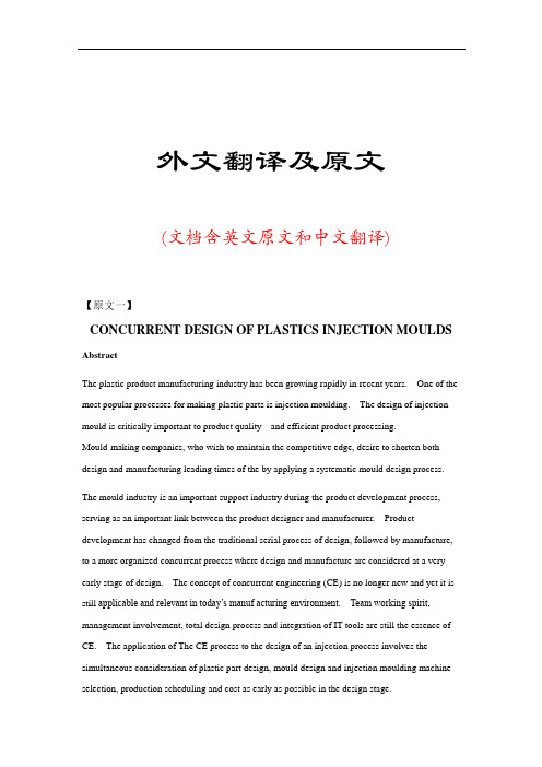
外文翻译及原文(文档含英文原文和中文翻译)【原文一】CONCURRENT DESIGN OF PLASTICS INJECTION MOULDS AbstractThe plastic product manufacturing industry has been growing rapidly in recent years. One of the most popular processes for making plastic parts is injection moulding. The design of injection mould is critically important to product quality and efficient product processing.Mould-making companies, who wish to maintain the competitive edge, desire to shorten both design and manufacturing leading times of the by applying a systematic mould design process. The mould industry is an important support industry during the product development process, serving as an important link between the product designer and manufacturer. Product development has changed from the traditional serial process of design, followed by manufacture, to a more organized concurrent process where design and manufacture are considered at a very early stage of design. The concept of concurrent engineering (CE) is no longer new and yet it is still applicable and relevant in today’s manuf acturing environment. Team working spirit, management involvement, total design process and integration of IT tools are still the essence of CE. The application of The CE process to the design of an injection process involves the simultaneous consideration of plastic part design, mould design and injection moulding machine selection, production scheduling and cost as early as possible in the design stage.This paper presents the basic structure of an injection mould design. The basis of this system arises from an analysis of the injection mould design process for mould design companies. This injection mould design system covers both the mould design process and mould knowledge management. Finally the principle of concurrent engineering process is outlined and then its principle is applied to the design of a plastic injection mould.Keywords :Plastic injection mould design, Concurrent engineering, Computer aided engineering, Moulding conditions, Plastic injection moulding, Flow simulation1.IntroductionInjection moulds are always expensive to make, unfortunately without a mould it can not be possible ho have a moulded product. Every mould maker has his/her own approach to design a mould and there are many different ways of designing and building a mould. Surely one of the most critical parameters to be considered in the design stage of the mould is the number of cavities, methods of injection, types of runners, methods of gating, methods of ejection, capacity and features of the injection moulding machines. Mould cost, mould quality and cost of mould product are inseparableIn today’s completive environment, computer aided mould filling simulation packages can accurately predict the fill patterns of any part. This allows for quick simulations of gate placements and helps finding the optimal location. Engineers can perform moulding trials on the computer before the part design is completed. Process engineers can systematically predict a design and process window, and can obtain information about the cumulative effect of the process variables that influence part performance, cost, and appearance.2.Injection MouldingInjection moulding is one of the most effective ways to bring out the best in plastics. It is universally used to make complex, finished parts, often in a single step, economically, precisely and with little waste. Mass production of plastic parts mostly utilizes moulds. The manufacturing process and involving moulds must be designed after passing through the appearance evaluation and the structure optimization of the product design. Designers face a hugenumber of options when they create injection-moulded components. Concurrent engineering requires an engineer to consider the manufacturing process of the designed product in the development phase. A good design of the product is unable to go to the market if its manufacturing process is impossible or too expensive. Integration of process simulation, rapid prototyping and manufacturing can reduce the risk associated with moving from CAD to CAM and further enhance the validity of the product development.3. Importance of Computer Aided Injection Mould DesignThe injection moulding design task can be highly complex. Computer Aided Engineering (CAE) analysis tools provide enormous advantages of enabling design engineers to consider virtually and part, mould and injection parameters without the real use of any manufacturing and time. The possibility of trying alternative designs or concepts on the computer screen gives the engineers the opportunity to eliminate potential problems before beginning the real production. Moreover, in virtual environment, designers can quickly and easily asses the sensitivity of specific moulding parameters on the quality and manufacturability of the final product. All theseCAE tools enable all these analysis to be completed in a meter of days or even hours, rather than weeks or months needed for the real experimental trial and error cycles. As CAE is used in the early design of part, mould and moulding parameters, the cost savings are substantial not only because of best functioning part and time savings but also the shortens the time needed to launch the product to the market.The need to meet set tolerances of plastic part ties in to all aspects of the moulding process, including part size and shape, resin chemical structure, the fillers used, mould cavity layout, gating, mould cooling and the release mechanisms used. Given this complexity, designers often use computer design tools, such as finite element analysis (FEA) and mould filling analysis (MFA), to reduce development time and cost. FEA determines strain, stress and deflection in a part by dividing the structure into small elements where these parameters can be well defined. MFA evaluates gate position and size to optimize resin flow. It also defines placement of weld lines, areas of excessive stress, and how wall and rib thickness affect flow. Other finite element design tools include mould cooling analysis for temperature distribution, and cycle time and shrinkage analysis for dimensional control and prediction of frozen stress and warpage.The CAE analysis of compression moulded parts is shown in Figure 1. The analysis cycle starts with the creation of a CAD model and a finite element mesh of the mould cavity. After the injection conditions are specified, mould filling, fiber orientation, curing and thermal history, shrinkage and warpage can be simulated. The material properties calculated by the simulation can be used to model the structural behaviour of the part. If required, part design, gate location and processing conditions can be modified in the computer until an acceptable part is obtained. After the analysis is finished an optimized part can be produced with reduced weldline (known also knitline), optimized strength, controlled temperatures and curing, minimized shrinkage and warpage.Machining of the moulds was formerly done manually, with a toolmaker checking each cut. This process became more automated with the growth and widespread use of computer numerically controlled or CNC machining centres. Setup time has also been significantly reduced through the use of special software capable of generating cutter paths directly from a CAD data file. Spindle speeds as high as 100,000 rpm provide further advances in high speed machining. Cutting materials have demonstrated phenomenal performance without the use of any cutting/coolant fluid whatsoever. As a result, the process of machining complex cores and cavities has been accelerated. It is good news that the time it takes to generate a mould is constantly being reduced. The bad news, on the other hand, is that even with all these advances, designing and manufacturing of the mould can still take a long time and can be extremely expensive.Figure 1 CAE analysis of injection moulded partsMany company executives now realize how vital it is to deploy new products to market rapidly. New products are the key to corporate prosperity. They drive corporate revenues, market shares, bottom lines and share prices. A company able to launch good quality products with reasonable prices ahead of their competition not only realizes 100% of the market before rival products arrive but also tends to maintain a dominant position for a few years even after competitive products have finally been announced (Smith, 1991). For most products, these two advantages are dramatic. Rapid product development is now a key aspect of competitive success. Figure 2 shows that only 3–7% of the product mix from the average industrial or electronics company is less than 5 years old. For companies in the top quartile, the number increases to 15–25%. For world-class firms, it is 60–80% (Thompson, 1996). The best companies continuously develop new products. AtHewlett-Packard, over 80% of the profits result from products less than 2 years old! (Neel, 1997)Figure 2. Importance of new product (Jacobs, 2000)With the advances in computer technology and artificial intelligence, efforts have been directed to reduce the cost and lead time in the design and manufacture of an injection mould. Injection mould design has been the main area of interest since it is a complex process involving several sub-designs related to various components of the mould, each requiring expert knowledge and experience. Lee et. al. (1997) proposed a systematic methodology and knowledge base for injection mould design in a concurrent engineering environment.4.Concurrent Engineering in Mould DesignConcurrent Engineering (CE) is a systematic approach to integrated product development process. It represents team values of co-operation, trust and sharing in such a manner that decision making is by consensus, involving all per spectives in parallel, from the very beginning of the productlife-cycle (Evans, 1998). Essentially, CE provides a collaborative, co-operative, collective and simultaneous engineering working environment. A concurrent engineering approach is based on five key elements:1. process2. multidisciplinary team3. integrated design model4. facility5. software infrastructureFigure 3 Methodologies in plastic injection mould design, a) Serial engineering b) Concurrent engineeringIn the plastics and mould industry, CE is very important due to the high cost tooling and long lead times. Typically, CE is utilized by manufacturing prototype tooling early in the design phase to analyze and adjust the design. Production tooling is manufactured as the final step. The manufacturing process and involving moulds must be designed after passing through the appearance evaluation and the structure optimization of the product design. CE requires an engineer to consider the manufacturing process of the designed product in the development phase.A good design of the product is unable to go to the market if its manufacturing process is impossible. Integration of process simulation and rapid prototyping and manufacturing can reduce the risk associated with moving from CAD to CAM and further enhance the validity of the product development.For years, designers have been restricted in what they can produce as they generally have todesign for manufacture (DFM) – that is, adjust their design intent to enable the component (or assembly) to be manufactured using a particular process or processes. In addition, if a mould is used to produce an item, there are therefore automatically inherent restrictions to the design imposed at the very beginning. Taking injection moulding as an example, in order to process a component successfully, at a minimum, the following design elements need to be taken into account:1. . geometry;. draft angles,. Non re-entrants shapes,. near constant wall thickness,. complexity,. split line location, and. surface finish,2. material choice;3. rationalisation of components (reducing assemblies);4. cost.In injection moulding, the manufacture of the mould to produce the injection-moulded components is usually the longest part of the product development process. When utilising rapid modelling, the CAD takes the longer time and therefore becomes the bottleneck.The process design and injection moulding of plastics involves rather complicated and time consuming activities including part design, mould design, injection moulding machine selection, production scheduling, tooling and cost estimation. Traditionally all these activities are done by part designers and mould making personnel in a sequential manner after completing injection moulded plastic part design. Obviously these sequential stages could lead to long product development time. However with the implementation of concurrent engineering process in the all parameters effecting product design, mould design, machine selection, production scheduling,tooling and processing cost are considered as early as possible in the design of the plastic part. When used effectively, CAE methods provide enormous cost and time savings for the part design and manufacturing. These tools allow engineers to virtually test how the part will be processed and how it performs during its normal operating life. The material supplier, designer, moulder and manufacturer should apply these tools concurrently early in the design stage of the plastic parts in order to exploit the cost benefit of CAE. CAE makes it possible to replace traditional, sequential decision-making procedures with a concurrent design process, in which all parties can interact and share information, Figure 3. For plastic injection moulding, CAE and related design data provide an integrated environment that facilitates concurrent engineering for the design and manufacture of the part and mould, as well as material selection and simulation of optimal process control parameters.Qualitative expense comparison associated with the part design changes is shown in Figure 4 , showing the fact that when design changes are done at an early stages on the computer screen, the cost associated with is an order of 10.000 times lower than that if the part is in production. These modifications in plastic parts could arise fr om mould modifications, such as gate location, thickness changes, production delays, quality costs, machine setup times, or design change in plastic parts.Figure 4 Cost of design changes during part product development cycle (Rios et.al, 2001)At the early design stage, part designers and moulders have to finalise part design based on their experiences with similar parts. However as the parts become more complex, it gets rather difficult to predict processing and part performance without the use of CAE tools. Thus for even relatively complex parts, the use of CAE tools to prevent the late and expensive design changesand problems that can arise during and after injection. For the successful implementation of concurrent engineering, there must be buy-in from everyone involved.5.Case StudyFigure 5 shows the initial CAD design of plastics part used for the sprinkler irrigation hydrant leg. One of the essential features of the part is that the part has to remain flat after injection; any warping during the injection causes operating problems.Another important feature the plastic part has to have is a high bending stiffness. A number of feeders in different orientation were added to the part as shown in Figure 5b. These feeders should be designed in a way that it has to contribute the weight of the part as minimum aspossible.Before the design of the mould, the flow analysis of the plastic part was carried out with Moldflow software to enable the selection of the best gate location Figure 6a. The figure indicates that the best point for the gate location is the middle feeder at the centre of the part. As the distortion and warpage of the part after injection was vital from the functionality point of view and it has to be kept at a minimum level, the same software was also utilised to yiled the warpage analysis. Figure 5 b shows the results implying the fact that the warpage well after injection remains within the predefined dimensional tolerances.6. ConclusionsIn the plastic injection moulding, the CAD model of the plastic part obtained from commercial 3D programs could be used for the part performance and injection process analyses. With the aid ofCEA technology and the use of concurrent engineering methodology, not only the injection mould can be designed and manufactured in a very short of period of time with a minimised cost but also all potential problems which may arise from part design, mould design and processing parameters could be eliminated at the very beginning of the mould design. These two tools help part designers and mould makers to develop a good product with a better delivery and faster tooling with less time and money.References1. Smith P, Reinertsen D, The time-to-market race, In: Developing Products in Half the Time. New York, Van Nostrand Reinhold, pp. 3–13, 19912.Thompson J, The total product development organization. Proceedings of the SecondAsia–Pacific Rapid Product Development Conference, Brisbane, 19963.Neel R, Don’t stop after the prototype, Seventh International Conference on Rapid Prototyping, San Francisco, 19974.Jacobs PF, “Chapter 3: Rapid Product Development” in Rapid Tooling: Technologies and Industrial Applications , Ed. Peter D. Hilton; Paul F. Jacobs, Marcel Decker, 20005.Lee R-S, Chen, Y-M, and Lee, C-Z, “Development of a concurrent mould design system: a knowledge based approach”, Computer Integrated Manufacturing Systems, 10(4), 287-307, 19976.Evans B., “Simultaneous Engineering”, Mechanical Engi neering , V ol.110, No.2, pp.38-39, 19987.Rios A, Gramann, PJ and Davis B, “Computer Aided Engineering in Compression Molding”, Composites Fabricators Association Annual Conference , Tampa Bay, 2001【译文一】塑料注塑模具并行设计塑料制品制造业近年迅速成长。
模具毕业设计外文翻译(英文+译文)
Injection MoldingThe basic concept of injection molding revolves around the ability of a thermoplastic material to be softened by heat and to harden when cooled .In most operations ,granular material (the plastic resin) is fed into one end of the cylinder (usually through a feeding device known as a hopper ),heated, and softened(plasticized or plasticized),forced out the other end of the cylinder, while it is still in the form of a melt, through a nozzle into a relatively cool mold held closed under pressure.Here,the melt cools and hardens until fully set-up. The mold is then opened, the piece ejected, and the sequence repeated.Thus, the significant elements of an injection molding machine become: 1) the way in which the melt is plasticized (softened) and forced into the mold (called the injection unit);2) the system for opening the mold and closing it under pressure (called the clamping unit);3) the type of mold used;4) the machine controls.The part of an injection-molding machine, which converts a plastic material from a sold phase to homogeneous seni-liguid phase by raising its temperature .This unit maintains the material at a present temperature and force it through the injection unit nozzle into a mold .The plunger is a combination of the injection and plasticizing device in which a heating chamber is mounted between the plunger and mold. This chamber heats the plastic material by conduction .The plunger, on each stroke; pushes unbelted plastic material into the chamber, which in turn forces plastic melt at the front of the chamber out through the nozzleThe part of an injection molding machine in which the mold is mounted, and which provides the motion and force to open and close the mold and to hold the mold close with force during injection .This unit can also provide other features necessary for the effective functioning of the molding operation .Movingplate is the member of the clamping unit, which is moved toward a stationary member. the moving section of the mold is bolted to this moving plate .This member usually includes the ejector holes and mold mounting pattern of blot holes or “T” slots .Stationary plate is the fixed member of the clamping unit on which the stationary section of the mold is bolted .This member usually includes a mold-mounting pattern of boles or “T” slots. Tie rods are member of the clamping force actuating mechanism that serve as the tension member of the clamp when it is holding the mold closed. They also serve as a gutted member for the movable plate .Ejector is a provision in the clamping unit that actuates a mechanism within the mold to eject the molded part(s) from the mold .The ejection actuating force may be applied hydraulically or pneumatically by a cylinder(s) attached to the moving plate, or mechanically by the opening stroke of the moving plate.Methods of melting and injecting the plastic differ from one machine to another and are constantly being implored .conventional machines use a cylinder and piston to do both jobs .This method simplifies machine construction but makes control of injection temperatures and pressures an inherently difficult problem .Other machines use a plasticizing extruder to melt the plastic and piston to inject it while some hare been designed to use a screw for both jobs :Nowadays, sixty percent of the machines use a reciprocating screw,35% a plunger (concentrated in the smaller machine size),and 5%a screw pot.Many of the problems connected with in ejection molding arise because the densities of polymers change so markedly with temperature and pressure. thigh temperatures, the density of a polymer is considerably cower than at room temperature, provided the pressure is the same.Therefore,if molds were filled at atmospheric pressure, “shrinkage” would make the molding deviate form the shape of the mold.To compensate for this poor effect, molds are filled at high pressure. The pressure compresses the polymer and allows more materials to flow into the mold, shrinkage is reduced and better quality moldings are produced.Cludes a mold-mounting pattern of bolt holes or “T” slots. Tie rods are members of the clamping force actuating mechanism that serve as the tension members of clamp when it is holding the mold closed. Ejector is a provision in the calming unit that actuates a mechanism within the mold to eject the molded part(s) form the mold. The ejection actuating force may be applied hydraulically or pneumatically by a cylinder(s) attached to the moving plate, or mechanically by the opening stroke of the moving plate.The function of a mold is twofold: imparting the desired shape to the plasticized polymer and cooling the injection molded part. It is basically made up of two sets of components: the cavities and cores and the base in which the cavities and cores are mounted. The mold ,which contains one or more cavities, consists of two basic parts :(1) a stationary molds half one the side where the plastic is injected,(2)Moving half on the closing or ejector side of the machine. The separation between the two mold halves is called the parting line. In some cases the cavity is partly in the stationary and partly in the moving section. The size and weight of the molded parts limit the number of cavities in the mold and also determine the machinery capacity required. The mold components and their functions are as following:(1)Mold Base-Hold cavity (cavities) in fixed, correctposition relative to machine nozzle.(2)Guide Pins-Maintain Proper alignment of entry into moldinterior.(3)Spree Bushing (spree)-Provide means of entry into moldinterior.(4)Runners-Conroy molten plastic from spree to cavities.(5)Gates-Control flow into cavities.(6)Cavity (female) and Force (male)-Control the size,shape and surface of mold article.(7)Water Channels-Control the temperature of mold surfacesto chill plastic to rigid state.(8)Side (actuated by came, gears or hydrauliccylinders)-Form side holes, slots, undercuts and threaded sections.(9)Vent-Allow the escape of trapped air and gas.(10)Ejector Mechanism (pins, blades, stripper plate)-Ejectrigid molded article form cavity or force.(11)Ejector Return Pins-Return ejector pins to retractedposition as mold closes for next cycle.The distance between the outer cavities and the primary spree must not be so long that the molten plastic loses too much heat in the runner to fill the outer cavities properly. The cavities should be so arranged around the primary spree that each receives its full and equal share of the total pressure available, through its own runner system (or the so-called balanced runner system).The requires the shortest possible distance between cavities and primary sprue, equal runner and gate dimension, and uniform culling.注射成型注射成型的基本概念是使热塑性材料在受热时熔融,冷却时硬化,在大部分加工中,粒状材料(即塑料树脂)从料筒的一端(通常通过一个叫做“料斗”的进料装置)送进,受热并熔融(即塑化或增塑),然后当材料还是溶体时,通过一个喷嘴从料筒的另一端挤到一个相对较冷的压和封闭的模子里。
注塑模具设计外文翻译

毕业设计(论文)外文资料翻译及原文(2012届)题目电话机三维造型与注塑模具设计指导教师院系工学院班级学号姓名二〇一一年十二月六日【译文一】塑料注塑模具并行设计Assist.Prof.Dr. A. Y AYLA /Prof.Dr. Paş a YAYLA摘要塑料制品制造业近年迅速成长。
其中最受欢迎的制作过程是注塑塑料零件。
注塑模具的设计对产品质量和效率的产品加工非常重要。
模具公司想保持竞争优势,就必须缩短模具设计和制造的周期。
模具是工业的一个重要支持行业,在产品开发过程中作为一个重要产品设计师和制造商之间的联系。
产品开发经历了从传统的串行开发设计制造到有组织的并行设计和制造过程中,被认为是在非常早期的阶段的设计。
并行工程的概念(CE)不再是新的,但它仍然是适用于当今的相关环境。
团队合作精神、管理参与、总体设计过程和整合IT工具仍然是并行工程的本质。
CE过程的应用设计的注射过程包括同时考虑塑件设计、模具设计和注塑成型机的选择、生产调度和成本中尽快设计阶段。
介绍了注射模具的基本结构设计。
在该系统的基础上,模具设计公司分析注塑模具设计过程。
该注射模设计系统包括模具设计过程及模具知识管理。
最后的原则概述了塑料注射模并行工程过程并对其原理应用到设计。
关键词:塑料注射模设计、并行工程、计算机辅助工程、成型条件、塑料注塑、流动模拟1、简介注塑模具总是昂贵的,不幸的是没有模具就不可能生产模具制品。
每一个模具制造商都有他/她自己的方法来设计模具,有许多不同的设计与建造模具。
当然最关键的参数之一,要考虑到模具设计阶段是大量的计算、注射的方法,浇注的的方法、研究注射成型机容量和特点。
模具的成本、模具的质量和制件质量是分不开的在针对今天的计算机辅助充型模拟软件包能准确地预测任何部分充填模式环境中。
这允许快速模拟实习,帮助找到模具的最佳位置。
工程师可以在电脑上执行成型试验前完成零件设计。
工程师可以预测过程系统设计和加工窗口,并能获得信息累积所带来的影响,如部分过程变量影响性能、成本、外观等。
塑料注射成型外文文献翻译、中英文翻译、外文翻译
塑料注射成型外文文献翻译、中英文翻译、外文翻译外文翻译原文:Injection MoldingMany different processes are used to transform plastic granules, powders, and liquids into product. The plastic material is in moldable form, and is adaptable to various forming methods. In most cases thermosetting materials require other methods of forming. This is recognized by the fact that thermoplastics are usually heated to a soft state and then reshaped before cooling. Theromosets, on the other hand have not yet been polymerized before processing, and the chemical reaction takes place during the process, usually through heat, a catalyst, or pressure. It is important to remember this concept while studying the plastics manufacturing processes and polymers used.Injection molding is by far the most widely used process of forming thermoplastic materials. It is also one of the oldest. Currently injection molding accounts for 30% of all plastics resin consumption. Since raw material can be converted by a single procedure, injection molding is suitable for mass production of plastics articles and automated one-step production of complex geometries. In most cases, finishing is not necessary. Typical products include toys, automotive parts, household articles, and consumer electronics goods.Since injection molding has a number of interdependent variables, it is a process of considerable complexity. The success of the injection molding operation is dependent not only in the proper setup of the machine hydraulics, barrel temperaturevariations, and changes in material viscosity. Increasing shot-to-shot repeatability of machine variables helps produce parts with tighter tolerance, lowers the level of rejects, and increases product quality (i.e., appearance and serviceability).The principal objective of any molding operation is the manufacture of products: to a specific quality level, in the shortest time, and using repeatable and fully automaticcycle. Molders strive to reduce or eliminate rejected parts in molding production. For injection molding of high precision optical parts, or parts with a high added value such as appliance cases, the payoff of reduced rejects is high.A typical injection molding cycle or sequence consists of five phases;1. Injection or mold filling2. Packing or compression3. Holding4. Cooling5. Part ejectionPlastic granules are fed into the hopper and through an in the injection cylinder where they are carried forward by the rotating screw. The rotation of the screw forces the granules under high pressure against the heated walls of the cylinder causing them to melt. As the pressure building up, the rotating screw is forced backward until enough plastic has accumulated to make the shot. The injection ram (or screw) forces molten plastic from the barrel, through the nozzle, sprue and runner system, and finally into the mold cavities. During injection, the mold cavity is filled volumetrically. When the plastic contacts the cold mold surfaces, it solidifies (freezes) rapidly to produce theskin layer. Since the core remains in the molten state, plastic follows through the core to complete mold filling. Typically, the cavity is filled to 95%~98% during injection. Then the molding process is switched over to the packing phase.Even as the cavity is filled, the molten plastic begins to cool. Since the cooling plastic contracts or shrinks, it gives rise to defects such as sink marks, voids, and dimensional instabilities. To compensate for shrinkage, addition plastic is forced into the cavity. Once the cavity is packed, pressure applied to the melt prevents molten plastic inside the cavity from back flowing out through the gate. The pressure must be applied until the gate solidifies. The process can be divided into two steps (packing and holding) or may be encompassed in one step(holding or second stage). During packing, melt forced into the cavity by the packing pressure compensates for shrinkage. With holding, the pressure merely prevents back flow of the polymer malt.After the holding stage is completed, the cooling phase starts. During, the part is held in the mold for specified period. The duration of the cooling phase depends primarily on the material properties and the part thickness. Typically, the part temperature must cool below the material’s ejection temperature. While cooling the part, the machine plasticates melt for the next cycle.The polymer is subjected to shearing action as well as the condition of the energy from the heater bands. Once the short is made, plastication ceases. This should occur immediately before the end of the cooling phase. Then the mold opens and the part is ejected.When polymers are fabricated into useful articles they are referred to as plastics, rubbers, and fibers. Some polymers, forexample, cotton and wool, occur naturally, but the great majority of commercial products are synthetic in origin. A list of the names of the better known materials would include Bakelite, Dacron, Nylon, Celanese, Orlon, and Styron.Previous to 1930 the use of synthetic polymers was not widespread. However, they should not be classified as new materials for many of them were known in the latter half of the nineteenth century. The failure to develop them during this period was due, in part, to a lack of understanding of their properties, in particular, the problem of the structure of polymers was the subject of much fruitless controversy.Two events of the twentieth century catapulted polymers into a position of worldwide importance. The first of these was the successful commercial production of the plastic now known as Bakelite. Its industrial usefulness was demonstrated in1912 and in the next succeeding years. T oday Bakelite is high on the list of important synthetic products. Before 1912 materials made from cellulose were available, but their manufacture never provided the incentive for new work in the polymer field such as occurred after the advent of Bakelite. The second event was concerned with fundamental studies of the nature polymers by Staudinger in Europe and by Carohers, who worked with the Du Pont company in Delaware. A greater part of the studies were made during the 1920’s. Staudinger’s work was primarily fundamental. Carother’s achievements led t o the development of our present huge plastics industry by causing an awakening of interest in polymer chemistry, an interest which is still strongly apparent today.The Nature of ThermodynamicsThermodynamics is one of the most important areas ofengineering science used to explain how most things work, why some things do not the way that they were intended, and why others things just cannot possibly work at all. It is a key part of the science engineers use to design automotive engines, heat pumps, rocket motors, power stations, gas turbines, air conditioners, super-conducting transmission lines, solar heating systems, etc.Thermodynamics centers about the notions of energy, the idea that energy is conserved is the first low of thermodynamics. It is starting point for the science of thermodynamics is entropy; entropy provides a means for determining if a process is possible.This idea is the basis for the second low of thermodynamics. It also provides the basis for an engineering analysis in which one calculates the maximum amount of useful that can be obtained from a given energy source, or the minimum amount of power input required to do a certain task.A clear understanding of the ideas of entropy is essential for one who needs to use thermodynamics in engineering analysis. Scientists are interested in using thermodynamics to predict and relate the properties of matter; engineers are interested in using this data, together with the basic ideas of energy conservation and entropy production, to analyze the behavior of complex technological systems.There is an example of the sort of system of interest to engineers, a large central power stations. In this particular plant the energy source is petroleum in one of several forms, or sometimes natural gas, and the plant is to convert as much of this energy as possible to electric energy and to send this energy down the transmission line.Simply expressed, the plant does this by boiling water andusing the steam to turn a turbine which turns an electric generator.The simplest such power plants are able to convert only about 25 percent of the fuel energy to electric energy. But this particular plant converts approximately 40 percent;it has been ingeniously designed through careful application of the basic principles of thermodynamics to the hundreds of components in the system.The design engineers who made these calculations used data on the properties of steam developed by physical chemists who in turn used experimental measurements in concert with thermodynamics theory to develop the property data.Plants presently being studied could convert as much as 55 percent of the fuel energy to electric energy, if they indeed perform as predicted by thermodynamics analysis.The rule that the spontaneous flow of heat is always from hotter to cooler objects is a new physical idea. There is noting in the energy conservation principle or in any other law of nature that specifies for us the direction of heat flow. If energy were to flow spontaneously from a block of ice to a surrounding volume of water, this could occur in complete accord with energy conservation. But such a process never happens. This idea is the substance of the second law of thermodynamics.Clear, a refrigerator, which is a physical system used in kitchen refrigerators, freezers, and air-conditioning units must obey not only the first law (energy conservation) but the second law as well.To see why the second law is not violated by a refrigerator, we must be careful in our statement of law. The second law of thermodynamics says, in effect, that heat never flowsspontaneously from a cooler to a hotter object.Or, alternatively, heat can flow from a cooler to a hotter object only as a result of work done by an external agency. We now see the distinction between an everyday spontaneous process, such as the flow of heat from the inside to the outside of a refrigerator.In the water-ice system, the exchange of energy takes place spontaneously and the flow of heat always proceeds from the water to the ice. The water gives up energy and becomes cooler while the ice receives energy and melts.In a refrigerator, on the other hand, the exchange of energy is not spontaneous. Work provided by an external agency is necessary to reverse the natural flow of heat and cool the interior at the expense of further heating the warmer surroundings.译文:塑料注射成型许多不同的加工过程习惯于把塑料颗粒、粉末和液体转化成最终产品。
塑料模具毕业设计中英文对照资料外文翻译文献
中英文对照资料外文翻译文献一个描述电铸镍壳在注塑模具的应用的技术研究摘要:在过去几年中快速成型技术及快速模具已被广泛开发利用. 在本文中,使用电芯作为核心程序对塑料注射模具分析. 通过差分系统快速成型制造外壳模型. 主要目的是分析电铸镍壳力学特征、研究相关金相组织,硬度,内部压力等不同方面,由这些特征参数以生产电铸设备的外壳. 最后一个核心是检验注塑模具.关键词:电镀;电铸;微观结构;镍1. 引言现代工业遇到很大的挑战,其中最重要的是怎么样提供更好的产品给消费者,更多种类和更新换代问题. 因此,现代工业必定产生更多的竞争性. 毫无疑问,结合时间变量和质量变量并不容易,因为他们经常彼此互为条件; 先进的生产系统将允许该组合以更加有效可行的方式进行,例如,如果是观测注塑系统的转变、我们得出的结论是,事实上一个新产品在市场上具有较好的质量它需要越来越少的时间快速模具制造技术是在这一领域, 中可以改善设计和制造注入部分的技术进步. 快速模具制造技术基本上是一个中小型系列的收集程序,在很短的时间内在可接受的精度水平基础上让我们获得模具的塑料部件。
其应用不仅在更加广阔而且生产也不断增多。
本文包括了很广泛的研究路线,在这些研究路线中我们可以尝试去学习,定义,分析,测试,提出在工业水平方面的可行性,从核心的注塑模具制造获取电铸镍壳,同时作为一个初始模型的原型在一个FDM设备上的快速成型。
不得不说的是,先进的电铸技术应用在无数的行业,但这一研究工作调查到什么程度,并根据这些参数,使用这种技术生产快速模具在技术上是可行的. 都产生一个准确的,系统化使用的方法以及建议的工作方法.2 制造过程的注塑模具薄镍外壳的核心是电铸,获得一个充满epoxic金属树脂的一体化的核心板块模具(图1)允许直接制造注射型多用标本,因为它们确定了新英格兰大学英文国际表卓华组织3167标准。
这样做的目的是确定力学性能的材料收集代表行业。
该阶段取得的核心[4],根据这一方法研究了这项工作,有如下:a,用CAD系统设计的理想对象b模型制造的快速成型设备(频分多路系统). 所用材料将是一个ABS塑料c一个制造的电铸镍壳,已事先涂有导电涂料(必须有导电).d无外壳模型e核心的生产是背面外壳环氧树脂的抗高温与具有制冷的铜管管道.有两个腔的注塑模具、其中一个是电核心和其他直接加工的移动版. 因此,在同一工艺条件下,同时注入两个标准技术制造,获得相同的工作。
模具外文翻译外文文献英文文献注塑模

模具外文翻译外文文献英文文献注塑模The Injection Molding1、The injection moldingInjection molding is principally used for the production of the thermoplastic parts,although some progress has been made in developing a method for injection molding some thermosetting materials.The problem of injection a method plastic into a mold cavity from a reservoir of melted material has been extremely difficult to solve for thermosetting plastic which cure and harden under such conditions within a few minutes.The principle of injection molding is quite similar to that of die-casting.The process consists of feeding a plastic compound in powered or granular form from a hopper through metering and melting stages and then injecting it into a mold.After a brief cooling period,the mold is opened and the solidified part ejected.Injection-molding machine operation.The advantage of injection molding are:(ⅰ)a high molding speed adapter for mass production is possible;(ⅱ)there is a wide choice of thermoplastic materials providing a variety of useful properties;(ⅲ)it is possible to mold threads,undercuts,side holes,and large thin section.2、The injection-molding machineSeveral methods are used to force or inject the melted plastic into the mold.The most commonly used system in the larger machines is the in-line reciprocating screw,as shown in Figure 2-1.The screw acts as a combination injection and plasticizing unit.As the plastic is fed to the rotating screw,it passes through three zones as shown:feed,compression,and metering.After the feed zone,the screw-flight depth is gradually reduced,force theplastic to compress.The work is converted to heat by conduction from the barrel surface.As the chamber in front of the screw becomes filled,it forces the screw back,tripping a limit switch that activates a hydraulic cylinder that forces the screw forward and injects the fluid plastic into the closed mold.An antiflowback valve presents plastic under pressure from escaping back into the screw flight.The clamping force that a machine is capable of exerting is part of the size designation and is measured in tons.A rule-of-thumb can be used to determine the tonnage required for a particular job.It is based on two tons of clamp force per square inch of projected area.If the flow pattern is difficult and the parts are thin,this may have to go to three or four tons.Many reciprocating-screw machines are capable of handing thermosetting plastic materials.Previously these materials were handled by compression or transfer molding.Thermosetting materials cure or polymerize in the mold and are ejected hot in the range of 375°C~410°C.T hermosetting parts must be allowed to cool in the mold in order or remove them without distortion. Thus thermosetting cycles can be faster.Of course the mold must be heated rather than chilled,as with thermoplastics.3、Basic Underfeed MouldA simple mould of this type is shown in Figure3-1,and the description of the design and the opening sequence follows.The mould consists of three basic parts,namely:the moving half,the floating cavity plate and the feed plate respectively.The moving half consists of The moving mould plate assembly,support block,backing plate,ejector assembly and the pin ejection system.Thus the moving half in this design is identical with the moving half of basic moulds.The floating cavity plate,which may be of the integer or insert-bolster design,is located on substantial guide pillars(not shown)fitted in the feed plate.These guide pillars must be of sufficient length to support the floating cavity plate over its full movement and still project to perform the function of alignment between the cavity and core when the mould is being closed.Guide bushes are fitted into the moving mould plate and the floating cavity plate respectively.The maximum movement of the floating cavity plate is controlled by stop or similar device.The moving mould plate is suitably bored to provide a clearance for the stop bolt assembly.The stop bolts must be long enough to provide sufficient space between the feed plate and the floating cavity plate for easy removal of the feed system.The minimum space provide for should be 65mm just sufficient for an operator to remove the feed system by hand if necessary.The desire operating sequence is for the first daylight to occur between the floating cavity plate.This ensures the sprue is pulled from the sprue bush immediately the mouldis opened.T o achieve this sequence,springs may be incorporated between the feed plate and the floating cavity plate.The springs should be strong enough to give an initial impetus to the floating cavity plate to ensure it moves away with the moving half.It is normal practice to mount the springs on the guide pillars(Figure3-2)and accommodate them in suitable pocket in the cavity plate.The major part of the feed system(runner and sprue)is accommodated in the feed plate to facilitate automatic operation,the runner should be of a trapezoidal form so that once it is pulled from the feed plate is can easily beextracted.Note that if a round runner is used,half the runner is formed in the floating cavity plate,where it would remain,and be prevented from falling or being wiped clear when the mould is opened.Now that we have considered the mould assembly in the some detail,we look at the cycle of operation for this type of mould.The impressions are filled via the feed system(Figure3-1(a))and after a suitable dwell period,the machine platens commence to open.A force is immediately exerted by the compression springs,which cause the floating cavity plate to move away with the moving half as previously discussed.The sprue is pulled from the sprue bush by the sprue puller.After the floating cavity plate has moved a predetermined distance,it is arrested by the stop bolts.The moving half continues to move back and the moldings,having shrunk on to the cores,are withdrawn from the cavities.The pin gate breaks at its junction with the runner(Figure3-1(b)).The sprue puller,being attached to the moving half,is pulled through the floating cavity plate and thereby release the feed system which is then free to fall between the floating cavity plate and the feed plate.The moving half continues to move back until the ejector system is operated and the moldings are ejected (Figure3-1(c)).When the mould is closed,the respective plates are returned to their molding position and the cycle is repeated.4、Feed SystemIt is necessary to provide a flow-way in the injection mould to connect the nozzle(of the injection machine)to each impression.This flow-way is termed the feed system.Normally thefeed system comprises a sprue,runner and gate.These terms applyequally to the flow-way itself,and to the molded material which is remove from the flow-way itself in the process of extracted the molding.A typical feed system for a four-impression,two plate-type mould is shown in Figure4-1.It is seen that the material passes through the sprue,main runner,branch runner and gate before entering the impression.As the temperature of molten plastic is lowered which going through the sprue and runner,the viscosity will rise;however,the viscosity is lowered by shear heat generated when going through the gate to fill the cavity.It is desirable to keep the distance that the material has to travel down to a minimum to reduce pressure and heat losses.It is for this reason that careful consideration must be given to the impression layout gate’s design.4.1.SprueA sprue is a channel through which to transfer molten plastic injected from the nozzle of the injector into the mold.It is a part of sprue bush,which is a separate part from the mold.4.2.RunnerA runner is a channel that guides molten plastic into the cavity of a mold.4.3.GateA gate is an entrance through which molten plastic enters the cavity.The gate has the following function:restricts the flow and the direction of molten plastic;simplifies cutting of a runner and moldings to simplify finishing of parts;quickly cools and solidifies to avoid backflow after molten plastic has filled up in the cavity.4.4.Cold slug wellThe purpose of the cold slug well,shown opposite the sprue,is theoretically to receive the material that has chilled at the front of nozzle during the cooling and ejection phase.Perhaps of greater importance is the fact that it provides position means whereby the sprue bush for ejection purposes.The sprue,the runner and the gate will be discarded after a part is complete.However,the runner and the gate are important items that affect the quality or the cost of parts.5、EjectionA molding is formed in mould by injecting a plastic melt,under pressure,into animpression via a feed system.It must therefore be removed manually.Furthermore,all thermoplastic materials contract as they solidify,which means that the molding will shrink on to the core which forms it.This shrinkage makes the molding difficult to remove. Facilities are provided on the injection machine for automatic actuation of an ejector system,and this is situated behind the moving platen.Because of this,the mould’s ejector system will be most effectively operated if placed in the moving half of the mould,i.e. the half attached to the moving platen.We have stated previously that we need to eject the molding from the core and it therefore follows that the core,too,will most satisfactorily be located in the moving half.The ejector system in a mould will be discussed under three headings,namely:(ⅰ)the ejector grid;(ⅱ)the ejector plate assembly; and(ⅲ)the method of ejection.5.1、Ejector gridThe ejector grid(Figure5-1)is that part of the mould which supports the mould plate and provides a space into which theejector plate assembly can be fitted and operated.The grid normally consists of a back plate on to which is mounted a number of conveniently shaped “support blocks”.The ejector plate assembly is that part of the mould to which the ejector element is attached.The assembly is contained in a pocket,formed by the ejector grid,directly behind the mould plate.The assembly(Figure5-2)consists of an ejector plate,a retaining plate and an ejector rod.One end of this latter member is threaded and it is screwed into the ejector plate.In this particular design the ejector rod function not only as an actuating member but also as a method of guiding the assembly.Note that the parallel portion of the ejector rod passes through an ejector rod bush fitted in the back plate of the mould.5.2、Ejection techniquesWhen a molding cools,it contracts by an amount depending on the material being processed.For a molding which has no internal form,for example,a solid rectangular block,the molding will shrink away from the cavity walls,thereby permitting a simple ejection technique to be adopted.However,when the molding has internal form,the molding,as it cools,will shrink onto the core and some positive type of ejection is necessary.The designer has several ejection techniques from which to choose,but in general,the choice will be restricted depending upon the shape of the molding.The basic ejection techniques are as follows:(ⅰ)pin ejection(ⅱ)sleeve ejection(ⅲ)stripper plate ejection and(Ⅳ)air ejection.Figure 2-1aFigure 2-1bFigure 3-1Figure 3-2Figure 4-1aFigure 4-1bFigure 5-1Figure 5-2注塑模1、注塑模尽管成型某些热固性材料的方法取得了一定的进步,但注塑模主要(还是)用来生产热塑性塑件。
模具设计相关专业毕业论文(外文原文+翻译)之翻译[管理资料]
可行成形图在汽车覆盖件冲压工艺高效设计的应用Dae-Cheol Ko a,Seung-Hoon Cha b,Sang-Kon Lee c,Chan-Joo Lee b,Byung-Min Kim d,*a ILIC, Pusan National University, 30 Jangjeon-Dong, Kumjeong-Gu, Busan609-735, South Koreab Precision Manufacturing Systems Division, Pusan National University, 30Jangjeon-Dong, Kumjeong-Gu, Busan 609-735, South Koreac PNU-IFAM, Joint Research Center, Pusan National University, 30Jangjeon-Dong, Kumjeong-Gu, Busan 609-735, South Koread School of Mechanical Engineering, Pusan National University, 30 Jangjeon-Dong, Kumjeong-Gu, Busan 609-735, South Korea摘要:本文提出使用可行的成形图来表示无断裂和起皱的安全区域,进而有效和快速地设计冲压工艺方法。
要确定可行的成形图,有限元分析对应于正交实验设计的过程变量组合。
随后,基于成形极限图的有限元分析,确定断裂和起皱的特征值。
所有组合的特征值在整个过程中,通过人工神经网络训练进行了一系列预测。
可行的成形图从所有组合的过程变量中最终确定。
以汽车覆盖件如转动架和车轮毂的冲压工艺作为实例来验证利用成形图的进行过程设计有效性。
有限元模拟结果与实验模拟结果比较表明,利用可行的成形图来进行冲压工艺的设计是有效的并适用于实际的过程。
塑料模具设计外文翻译资料
模具毕业设计英译汉(Injection_molding)
Injection moldingInjection molding (British English: moulding) is a manufacturing process for producing parts from both thermoplastic and thermosetting plastic materials. Material is fed into a heated barrel, mixed, and forced into a mold cavity where it cools and hardens to the configuration of the mold cavity.After a product is designed, usually by an industrial designer or an engineer, molds are made by a moldmaker (or toolmaker) from metal, usually either steel or aluminum, and precision-machined to form the features of the desired part. Injection molding is widely used for manufacturing a variety of parts, from the smallest component to entire body panels of cars.ApplicationsInjection molding is used to create many things such as wire spools, packaging, bottle caps, automotive dashboards, pocket combs, and most other plastic products available today. Injection molding is the most common method of part manufacturing. It is ideal for producing high volumes of the same object.Some advantages of injection molding are high production rates, repeatable high tolerances, the ability to use a wide range of materials, low labor cost, minimal scrap losses, and little need to finish parts after molding. Some disadvantages of this process are expensive equipment investment, potentially high running costs, and the need to design moldable parts.EquipmentPaper clip mold opened in molding machine; the nozzle is visible at rightMain article: Injection molding machineInjection molding machines consist of a material hopper, an injection ram or screw-type plunger, and a heating unit. They are also known as presses, they hold the molds in which the components are shaped. Presses are rated by tonnage, which expresses the amount of clamping force that the machine can exert. This force keeps the mold closed during the injection process. Tonnage can vary from less than 5 tons to 6000 tons, with the higher figures used in comparatively few manufacturingoperations. The total clamp force needed is determined by the projected area of the part being molded. This projected area is multiplied by a clamp force of from 2 to 8 tons for each square inch of the projected areas. As a rule of thumb, 4 or 5 tons/in2 can be used for most products. If the plastic material is very stiff, it will require more injection pressure to fill the mold, thus more clamp tonnage to hold the mold closed. The required force can also be determined by the material used and the size of the part, larger parts require higher clamping force.MoldMold or die are the common terms used to describe the tooling used to produce plastic parts in molding.Since molds have been expensive to manufacture, they were usually only used in mass production where thousands of parts were being produced. Typical molds are constructed from hardened steel, pre-hardened steel, aluminum, and/or beryllium-copper alloy. The choice of material to build a mold from is primarily one of economics; in general, steel molds cost more to construct, but their longer lifespan will offset the higher initial cost over a higher number of parts made before wearing out. Pre-hardened steel molds are less wear-resistant and are used for lower volume requirements or larger components. The typical steel hardness is 38-45 on the Rockwell-C scale. Hardened steel molds are heat treated after machining. These are by far the superior in terms of wear resistance and lifespan. Typical hardness ranges between 50 and 60 Rockwell-C (HRC). Aluminum molds can cost substantially less, and, when designed and machined with modern computerized equipment, can be economical for molding tens or even hundreds of thousands of parts. Beryllium copper is used in areas of the mold that require fast heat removal or areas that see the most shear heat generated. The molds can be manufactured either by CNC machining or by using Electrical Discharge Machining processes.Mold DesignStandard two plates tooling –core and cavity are inserts in a mold base – "Family mold" of 5 different partsThe mold consists of two primary components, the injection mold (A plate) and the ejector mold (B plate). Plastic resin enters the mold through a sprue in the injection mold, the sprue bushing is to seal tightly against the nozzle of the injection barrel of the molding machine and to allow molten plastic to flow from the barrel into the mold, also known as cavity The sprue bushing directs the molten plastic to the cavity images through channels that are machined into the faces of the A and B plates. These channels allow plastic to run along them, so they are referred to as runners.The molten plastic flows through the runner and enters one or more specialized gates and into the cavity geometry to form the desired part.The amount of resin required to fill the sprue, runner and cavities of a mold is a shot. Trapped air in the mold can escape through air vents that are ground into the parting line of the mold. If the trapped air is not allowed to escape, it is compressed by the pressure of the incoming material and is squeezed into the corners of the cavity, where it prevents filling and causes other defects as well. The air can become so compressed that it ignites and burns the surrounding plastic material. To allow for removal of the molded part from the mold, the mold features must not overhang one another in the direction that the mold opens, unless parts of the mold are designed to move from between such overhangs when the mold opens (utilizing components called Lifters).Sides of the part that appear parallel with the direction of draw (The axis of the cored position (hole) or insert is parallel to the up and down movement of the mold as it opens and closes)are typically angled slightly with (draft) to ease release of the part from the mold. Insufficient draft can cause deformation or damage. The draft required for mold release is primarily dependent on the depth of the cavity: the deeper the cavity, the more draft necessary. Shrinkage must also be taken into account when determining the draft required.If the skin is too thin, then the molded part will tend to shrink onto the cores that form them while cooling, and cling to those cores or part may warp, twist, blister or crack when the cavity is pulled away. The mold is usually designed so that the moldedpart reliably remains on the ejector (B) side of the mold when it opens, and draws the runner and the sprue out of the (A) side along with the parts. The part then falls freely when ejected from the (B) side. Tunnel gates, also known as submarine or mold gate, is located below the parting line or mold surface. The opening is machined into the surface of the mold on the parting line. The molded part is cut (by the mold) from the runner system on ejection from the mold. Ejector pins, also known as knockout pin, is a circular pin placed in either half of the mold (usually the ejector half), which pushes the finished molded product, or runner system out of a mold.The standard method of cooling is passing a coolant (usually water) through a series of holes drilled through the mold plates and connected by hoses to form a continueous pathway. The coolant absorbs heat from the mold (which has absorbed heat from the hot plastic) and keeps the mold at a proper temperature to solidify the plastic at the most efficient rate.To ease maintenance and venting, cavities and cores are divided into pieces, called inserts, and sub-assemblies, also called inserts, blocks, or chase blocks. By substituting interchangeable inserts, one mold may make several variations of the same part.More complex parts are formed using more complex molds. These may have sections called slides, that move into a cavity perpendicular to the draw direction, to form overhanging part features. When the mold is opened, the slides are pulled away from the plastic part by using st ationary “angle pins” on the stationary mold half. These pins enter a slot in the slides and cause the slides to move backward when the moving half of the mold opens. The part is then ejected and the mold closes. The closing action of the mold causes the slides to move forward along the angle pins.Some molds allow previously molded parts to be reinserted to allow a new plastic layer to form around the first part. This is often referred to as overmolding. This system can allow for production of one-piece tires and wheels.2-shot or multi-shot molds are designed to "overmold" within a single molding cycle and must be processed onspecialized injection molding machines with two or more injection units. This process is actually an injection molding process performed twice. In the first step, the base color material is molded into a basic shape. Then the second material is injection-molded into the remaining open spaces. That space is then filled during the second injection step with a material of a different color.A mold can produce several copies of the same parts in a single "shot". The number of "impressions" in the mold of that part is often incorrectly referred to as cavitation. A tool with one impression will often be called a single impression(cavity) mold.A mold with 2 or more cavities of the same parts will likely be referred to as multiple impression (cavity) mold.Some extremely high production volume molds (like those for bottle caps) can have over 128 cavities.In some cases multiple cavity tooling will mold a series of different parts in the same tool. Some toolmakers call these molds family molds as all the parts are related.Effects on the material propertiesThe mechanical properties of a part are usually little affected. Some parts can have internal stresses in them. This is one of the reasons why it's good to have uniform wall thickness when molding. One of the physical property changes is shrinkage. A permanent chemical property change is the material thermoset, which can't be remelted to be injected again.Tool MaterialsTool steel or beryllium-copper are often used. Mild steel, aluminum, nickel or epoxy are suitable only for prototype or very short production runs.Modern hard aluminum (7075 and 2024 alloys) with proper mold design, can easily make molds capable of 100,000 or more part life.Geometrical PossibilitiesThe most commonly used plastic molding process, injection molding, is used to create a large variety of products with different shapes and sizes. Most importantly, they can create products with complex geometry that many other processes cannot. There are a few precautions when designing something that willbe made using this process to reduce the risk of weak spots. First, streamline your product or keep the thickness relatively uniform. Second, try and keep your product between 2 to20 inches.The size of a part will depend on a number of factors (material, wall thickness, shape,process etc.). The initial raw material required may be measured in the form of granules, pellets or powders. Here are some ranges of the sizes.MachiningMolds are built through two main methods: standard machining and EDM. Standard Machining, in its conventional form, has historically been the method of building injection molds. With technological development, CNC machining became the predominant means of making more complex molds with more accurate mold details in less time than traditional methods.The electrical discharge machining (EDM) or spark erosion process has become widely used in mold making. As well as allowing the formation of shapes that are difficult to machine, the process allows pre-hardened molds to be shaped so that no heat treatment is required. Changes to a hardened mold by conventional drilling and milling normally require annealing to soften the mold, followed by heat treatment to harden it again. EDM is a simple process in which a shaped electrode, usually made of copper or graphite, is very slowly lowered onto the mold surface (over a period of many hours), which is immersed in paraffin oil. A voltage applied between tool and mold causes spark erosion of the mold surface in the inverse shape of the electrode.CostThe cost of manufacturing molds depends on a very large set of factors ranging from number of cavities, size of the parts (and therefore the mold), complexity of the pieces, expected tool longevity, surface finishes and many others. The initial cost is great, however the piece part cost is low, so with greater quantities the overall price decreases.Injection processSmall injection molder showing hopper, nozzle and die areaWith Injection Molding, granular plastic is fed by gravity from a hopper into a heated barrel. As the granules are slowly moved forward by a screw-type plunger, the plastic is forced into a heated chamber, where it is melted. As the plunger advances, the melted plastic is forced through a nozzle that rests against the mold, allowing it to enter the mold cavity through a gate and runner system. The mold remains cold so the plastic solidifies almost as soon as the mold is filled.Injection Molding CycleThe sequence of events during the injection mold of a plastic part is called the injection molding cycle. The cycle begins when the mold closes, followed by the injection of the polymer into the mold cavity. Once the cavity is filled, a holding pressure is maintained to compensate for material shrinkage. In the next step, the screw turns, feeding the next shot to the front screw.This causes the screw to retract as the next shot is prepared. Once the part is sufficiently cool, the mold opens and the part is ejected.Molding trialWhen filling a new or unfamiliar mold for the first time, where shot size for that mold is unknown, a technician/tool setter usually starts with a small shot weight and fills gradually until the mold is 95 to 99% full. Once this is achieved a small amount of holding pressure will be applied and holding time increased until gate freeze off (solidification time) has occurred. Gate solidification time is an important as it determines cycle time, which itself is an important issue in the economics of the production process. Holding pressure is increased until the parts are free of sinks and part weight has been achieved. Once the parts are good enough and have passed any specific criteria, a setting sheet is produced for people to follow in the future. The method to setup an unknown mold the first time can be supported by installing cavity pressure sensors. Measuring the cavity pressure as a function of time can provide a good indication of the filling profile of the cavity. Once the equipment is set to successfully create the molded part, modern monitoring systems can save a reference curve of the cavity pressure. With that it is possible toreproduce the same part quality on another molding machine within a short setup time.Tolerances and SurfacesMolding tolerance is a specified allowance on the deviation in parameters such as dimensions, weights, shapes, or angles, etc. To maximize control in setting tolerances there is usually a minimum and maximum limit on thickness, based on the process used.Injection molding typically is capable of tolerances equivalent to an IT Grade of about 9–14. The possible tolerance of a thermoplastic or a thermoset is ±0.008 to ±0.002 inches. Surface finishes of two to four microinches or better are can be obtained. Rough or pebbled surfaces are also possible.Lubrication and CoolingObviously, the mold must be cooled in order for the production to take place. Because of the heat capacity, inexpensiveness, and availability of water, water is used as the primary cooling agent. To cool the mold, water can be channeled through the mold to account for quick cooling times. Usually a colder mold is more efficient because this allows for faster cycle times. However, this is not always true because crystalline materials require the opposite: a warmer mold and lengthier cycle time.InsertsMetal inserts can be also be injection molded into the workpiece. For large volume parts the inserts are placed in the mold using automated machinery. An advantage of using automated components is that the smaller size of parts allows a mobile inspection system that can be used to examine multiple parts in a decreased amount of time. In addition to mounting inspection systems on automated components, multiple axial robots are also capable of removing parts from the mold and place them in latter systems that can be used to ensure quality of multiple parameters. The ability of automated components to decrease the cycle time of the processes allows for a greater output of quality parts.Specific instances of this increased efficiency include the removal of parts from the mold immediately after the parts are created and use in conjunction with vision systems. Theremoval of parts is achieved by using robots to grip the part once it has become free from the mold after in ejector pins have been raised. The robot then moves these parts into either a holding location or directly onto an inspection system, depending on the type of product and the general layout of the rest of the manufacturer's production facility. Visions systems mounted on robots are also an advancement that has greatly changed the way that quality control is performed in insert molded parts. A mobile robot is able to more precisely determine the accuracy of the metal component and inspect more locations in the same amount of time as a human inspector.注塑成型注射制模(Injection moldin)是一种生产由热塑性塑料或热固性塑料所构成的部件的过程。
塑料模具CAD集成技术外文文献翻译、中英文翻译、外文翻译
附录1 英文原文The molding tool CAD gathers the technique Contents brief summary: Pass to analyze the calculator the assistance inject the mold design with make in the each link commonly shared of technique with information, this text announces to public to inject the mold CAD gathers technical and basic content, and the research heat that put forward it orders with trend.0, prefaceThe molding tool CAD gathers the technique is an important molding tool forerunner manufacturing technique, is the item reforms with the high technique traditional technical and important key in molding tool technique. From 6 5 plan beginning,Our country contain many molding tools business enterprise adoption CAD technique, especially recent years, the technical application in CAD is more and more widespread with thorough, shortened consumedly molding tool design period, Increases to make the mold quantity with the manufacturing ability that complicated molding tool.However, gather to the molding tool CAD because of many business enterprises technique cognition shortage, investment take the blindness, can't produce result nicely,Result in very big and wasted.This text gathers for the plastics molding tool CAD technique and its applications announce some standpoint, provide everybody consults.1, the plastics molding tool CAD gathers techniqueThe manufacturing of the plastics molding tool comtains the construction design of the shape design, molding tool and the number of the analysis, molding tools that include the plastics products control to process( I I , electricity process, the line incises etc.), throw the light with go together with to try the mold and take shape manufacturing etc. quickly.The each link a CAD for involving unit technique has:The shape design( CAD) with the construction, fast anti of the product shapebeg( RE), construction analysis with excellent turn the design( CAE), lend support to the manufacturing( CAM) and process the process conjecture imitate true( SIMULATION), product and molding tools take shape( RP) quickly, assistance craft process( CAPP) with product data management technique( PDM) etc..The plastics molding tool CAD gathers technique,Is to gather plastics molding tool manufacturing process a various units for involving technique get up, unify the database to deliver the format with the document, realize the information gather share with the data resources, from but shorten the design manufacturing period of the molding tool consumedly,Increases to make the mold quantity.2, the CAD design of the plastics product begs with fast anti of the shapeThe plastics molding tool that proceed the square one designs the manufacturing is the design of the EU a product.The traditional product design method is a design to product of three is conceive outline to use two I plane chart papers expresses to come out, marking clearly the craft and starting construction the method on the diagram paper, This kind of met hod comes to a decision the simple of a design sketch and can''ts control to make the quantity directly.The modern design method is a design establish the product directly on the computer of three the model of I ,According to the product three I models proceed the molding tool construction the design and excellent turn the design,Design according to the molding tool construction again three I models proceed to process to weave the distance and establishment crafts plan.This kind of method makes product model design, molding tool construction design, process to weave distance and technological designs regard a data as the foundation, realizing the data share, Can not only increases to design the efficiency quickly, but also can guarantee the quantity, decline low cost.The source of the computer EU a product model has three kinds of:Making use of the CAD system software proceeds the product model the design and make use of the real object measures fast anti in proceeding beg to set up the mold andmake use of the standard format document of the other the system of CAD.Source method that aim at these three kinds of products model,Have studied every kind of technique now to the design efficiency that increases product model with quantity.The underneath further analyzes every kind of technical content with the characteristics.Making use of the CAD system software proceeds the product model design,Its technique includes primarily two is are several why the sketch draws, two the parameter of is turn the design of the sketch, three i entity shape design, three icharacteristic shape design, three the parameter of is turn the entity shape the design, three i curved face shape design, free shape in space design, the external appearance of the product exaggerates, product of dynamic advertise to design the etc..These softwareses contain many typical representatives.Two the software of is have: ME10, CADKEY, AUTOCAD, DHCAD, Genis, etc. of Sigraph; three the software of is have:UGII, PRO/ E, IDEAS, CATIA, etc. of EUCLID; free shape in product and advertise the software of the design have:Alias, etc. of CDRS.Two is are several why the sketch draws is to make use of the flat surface CAD software draw the spare parts sketch, then replace the handicraft painting with the calculator; but two the parameter of is turn,Then the calculator realizes the sketch changes the deal designs, making modification more convenient; threeishape designs is a true shape that the product that the arithmetic figure turn design, it expressed completely product,Can be further to designs for the molding tool, analysis with processes the mathematics model of the necessity of offering; the free shape in space design is the art of the product shape to design, making product been not only is a function product, but also art article.It is every kind of need that the external appearance of the product exaggerate that product of the result designs, making product more beautiful, the color can attract people more; the dynamic advertisement design of the product is a result that design to make topromote the advertisement directly the product,Proceed the market expansion.Making use of the real object measures fast anti of proceeding beg to set up mold is current investigative a little bit hot of a,It is an important technique that product imitate the type foundation go forward a line of the product modification designs.Its basic principle is to passes three coordinateses measure the machine, laser measure machine or electronicses copy the few ÒÇ to proceed to scan the diagraph to the real object,The data of large quantity that arithmetic figure turn that gets to measures the acquisition orders anti that send into the high class CAD software beg mold piece or appropriative anti beg the software inside, anti beg the software can read directly a data cluster,Combining can proceed the editor, filter, tidy up, beg the ¾« to a data cluster, row preface, part modification and reorganization, then automatic born curved face, It is end to acquire together the real object precision is consistent of or computer EU a product model that pass through reforms.This way can increases biggest new product design velocity.Current mature curved face anti beg to set up the mold software has: Surfacer,Cimatronrenge, etc. of Strim100.Make use of the standard format document of the other the system of CAD to set up the mold, this way than convenience.Because the world of the market turns with the technical development in the network of INTERNET,The CAD technique exchanges of the molding tool business enterprise with cooperate to have many pass the CAD document method proceed.Because the CAD system category is more, therefore documentary format must follow the international standard,Such as the DXF, IGES, STEP, VDA, etc. of STL.Pass to read standard format document to establish directly or establish the product model after modifying, since can quickly, deepen the customer and the exchanges of the molding tool factory house,Also can shorten the product the design the period.3, the CAD design of the molding tool and analysisThe CAD design of the molding tool, analysis,Include to divide the type, certain type C» according to the product model molding tool of proceeding the design with the type D¾ , molding tool structural and detailed design, the plastics ³a fills process analysis etc. a few aspects.Make use of the advanced characteristic shape software,such as PRO/ E, etc. of UGII, the very easily certain dividing the type,Born top and bottom mold C»with mold D¾ , then the proceeding flows a way, sprinkle a people and cool off the pipe line of arrange etc..Made sure these designses data hereafter, then make use of the molding tool analysis software,Proceed such as the MOLDFLOW, CFLOW the plastics take shape the process analysis.According to the software of MOLDFOLW with it of the material, craft database of plentifulness, pass the importation take shape the craft parameter,Can the development imitate the true analysis plastics to inject in note EU mold C»the process flows the circumstance( the plastics with sprinkle a people more inject remits to flow the analysis of ÎAE ), analyze the temperature pressure variety circumstance and analyze to note EU a ²D remaining should dint etc.,According to analyze the circumstance to the rationality that check the molding tool construction, flow quantity problem etc. of the rationality, product of the appearance.For example whether the esse sprinkles to note the system not reasonable, appear to flow way with sprinkle a position size not appropriate,Can''t equilibrium alive with type C»; whether to exsit product construction absurdity or molding tool constructions or not is not reasonable, appearing the product A dissatisfied( namely short shoot the phenomenon); whether to cool off asymmetry or not, the influence produces the efficiency with product quantity;Whether the esse notes the craft of EU wrong, appear the song of CI of the product transform etc..The molding tool passes the CAD the design with analyze, can dissolve mistake at design the stage, increase to try once the mold the success the rate.At plastics molding tool design with analyze to apply many new computer.aideds technique this stage, if the parameter turns technique, characteristic shape technique, database technique etc..There is many standards piece in the plastics molding tool, Turn such as the standard mold a parameter for outing organization, sprinkling noting system, cooling system...etc. can adopting basing on database managing the characteristic shape design method proceed the design or establish the standard a a, like this since can realize the data share,Can satisfy the customer again to the at any time modifying of the design, make the design analysis of the molding tool fast, accurate, efficiently.The parameter turns the characteristic shape can not only describe the product completely then several why sketch information,And can acquire accuracy, material and assemble etc. informations of the product, its a product for establishing model is a kind of apting to handle and can reflect design intention with process the model of the characteristic.Therefore,The parameter turns the characteristic shape technique is an one of the most important technique in process in manufacturing in molding tools.4, the technical application in CAM of the molding tool, process to imitate true and ml;I processing, line incising to process, electricity spark processing to wait.The technique of CAM rises in the type C» , type D¾ of the complicated molding tool and the I I of the electrodes process particularly more important function.Its main technique characteristics includes:(1) the O , ¾« processes the knife have the track excellent to turn the programming with the instruction of NC creation,(2) the knife has the category, characteristic to establish with the material ,(3) slicing the Ï÷process the craft parameter to really settle,(4)The commonness slices the Ï÷ to slice with the high speed the characteristic that I process controls,(5) over slice the check with process the superficial accuracy control,(6) processing the computer entity of the process imitate the realistic I ,(7) The computercontrol number controls the technique of DNC and clusters of the machine bed control the technical and applied etc..Need the CAD specially in technical application in CAM three I product model data.More profession computer plait distance software,such as MASTERCAM, UNIMOD, etc. of CIMATRON, when the plait distance of many curved faces processes have the higher request to the curved face model of the product,Intend with the high accuracy of the curved face to match such as the directional consistency, curved face in U, V of the close together curved face, inclined rate in curved face continuous variety etc..In high class CAD/ the integral whole of CAM turn system,( such as UGII, PRO/ E)Because making use of the parameter turns the characteristic shape design with same database technique, making the type C of the product model data, molding tool have the track data to have got the inside contact with the type D¾ model data, knife, The modification knife of the product model has the track to also modify automatically.The molding tool processes the entity imitates the true technique more and more mature, also is more and more valued by people.It is mimicry machine bed that processing the entity imitate process the process on the computer, can keep the result that view reflect process,Can takes the gauge of directly quantity that after processing spare parts, can check the mistake that process.At check quantity that after processing spare parts, can at the computer is last to process behind of the entity model proceeds the aleatoric EE slices, Measure its size directly with the accuracy.Therefore, it can dissolve mistake at process the stage of craft plait distance design, reduce to repair after processing with return the work, increases consumedly the manufacturing efficiency of the molding tool with quantity.5, plastics product and its molding tools take shape the manufacturing quicklyPlastics product and its molding tools use the computer CAD techniquewdesign after completing, can pass the fleetness take shape the technique make.This is themanufacturing technique of a kind of all new concept,It abandoned the traditional machine processes the method.Its take shape principle is three I CAD entity models are long.lost set up a series of a layer data of the thickness, make use of the laser take shape machine or others take shape the equipments read these datas,Increase the method technique with the material, pile up the each layer to take shape one by one in order.This technique calls the fleetness to take shape the technique automatically.( Rapid Prototype)It is also a CAD to gather the technical importance constitutes the part.The first pedestal takes shape the equipments quickly to bear in the United States a company in 1987, because of its characteristics is to has nothing to do with the complicated degree of the product of the manufacturing, bringing the manufacturing industry the enormous vibration.Henceforth decade,Take shape quickly the technique be flown to develop soon, the category of the equipments also piles up one after another,Turn from the material I the method can is divided into the laser with not the laser burns the knot method( SLS), solid surface layer shape method( SGC), layer a manufacturing method( LOM) and melt to sink to accumulate the method( FDM), district constituency glues the knot method( DSPC), laser spirit to sink to accumulate method( SALD) etc. mutually.Every kind of method characteristics is:The method of SLA is applied at the earliest stage of took shape the technique quickly, the early market occupied the bigger cent sum, but is narrow because of the material scope, the cost is higher, taking shape the piece was heat.proof and bore the burthen with applied color the ability low,The recent years was gradually replaced by the other method.The method of FDM because of taking shape the speed quick, the cost is low, get the good application in plastics product profession, because the size of the spare parts is small, accuracy bad, Also suffer certainly of restrict.The method of LOM because of adoption paper or is outline edge that thin slice plastics, the cost is low, and the laser projects light upon eachlayer only, as a result take shape the speed quick,But the product surface quantity is bad.The method of SLS proceeds to burn the knot with the laser, adoptive material than wide, if the plastics,A¯ anticipates, porcelain and ceramics, metals etc. all can take shape, taking shape the piece is heat.proof and bear the burthen with apply color the ability stronger,Have the extensive and applied foreground.The other method also gets the application in some special kinds process.According to above take shape the method characteristics, take shape the technical function quickly to consist in primarily:The manufacturing useds for the design with the on trial product model, make to used for the small the molding tool that batch quantity produce to process with the special spare parts in small batch quantity.Take shape the product model of the technique manufacturing quickly in the aspects of material the ratio tradition processes the product model of the method manufacturing has the difference,But in shape and sizes almost complete similar, and there is certain machine strength, can make the function experiment, handles through surface at the same time, looking similar to true product,Can advertise the propaganda material.Take shape the molding tool of the technique manufacturing quickly,Is a soft material to take shape the mold( the mold of A¯ , wreath oxygen resin mold, ¹è rubber mold, low EU orders the metal alloy casts mold etc.) primarily to synthesize the hard type in material C mold with porcelain and ceramics or metals »ùs now.Hard mold in manufacturing the hour can take shape with the fleetness the spare parts makes the female die,Create first the soft mold between wreath oxygen resin mold or other material, sprinkle to note porcelain and ceramics or gypsum molds in soft mold, then sprinkle the steel of Öý steel mold; or sprinkle the admixture that note in soft mold chemistry contain steel powder glue knot,Proceed to burn to become the steel mold.Take shape the steel mold of the techniquemanufacturing quickly to process after needing further did to throw light etc., make into the small batch quantity produce of note the mold of EU .Because the molding tool sprinkles to note or burn the knot with the steel powder but,Material and common molding tool steel contain certain margin, therefore, the life span is shorter, cans make to manufacture on a trial basis product or small batch quantities produce.Moreover, taking shape the technique quickly can also manufacture the special spare parts,If make with the metallurgy powder legal system the metals electrode, nicety cast the legal system makes the copper electrode, ND mold legal system makes graphite electrode etc..Take shape the technique creation molding tool quickly to model the equipments with the product, all is STL to read CAD system creation or CLI etc. document format datas,Different document format data to the product accuracy of the creation contain bigger margin, therefore, study the system of CAD to take shape quickly the document format of the equipments output to have the very important meaning.6, the molding tool CAD gathers technical development trendA calculator for saying, molding tool CAD gathering technique is applying in molding tool making each link assistance technique on the ×U with each link information that realizes the technique gathers.Obviously,The information gathers unify with data the management is a key.The information of the product is to pierces through in the design, analyze, process, examine, assemble a stage,Fluency, solution data format that realizes each link information standardizes and the data maintenance is a point with future CAD that share to gather technique development.The system of PDM emergence is to resolve this problem brought the first light of day.It is molding tool business enterprise application CAD that the system of PDM puts into practice gather technical and important lesson.Design in molding tool manufacturing aspect,The intelligence that imply the research, high speed that abundantexpert''s knowledge turn molding tool CAD/ the system of CAM slices theI÷ processes and its plait distance etc. is a trend that future study the development.2 中文翻译塑料模具CAD集成技术内容提要:通过分析计算机辅助注射模设计和制造的各个环节中共享的技术和信息,本文揭示了注射模CAD的集成技术的根本内涵,并提出了它的研究热点和趋势。
- 1、下载文档前请自行甄别文档内容的完整性,平台不提供额外的编辑、内容补充、找答案等附加服务。
- 2、"仅部分预览"的文档,不可在线预览部分如存在完整性等问题,可反馈申请退款(可完整预览的文档不适用该条件!)。
- 3、如文档侵犯您的权益,请联系客服反馈,我们会尽快为您处理(人工客服工作时间:9:00-18:30)。
长江大学工程技术学院毕业设计(论文)外文翻译外文题目A technical note on the characterization ofelectroformed nickel shells for their application toinjection molds译文题目一个描述电铸镍壳在注塑模具的应用的技术研究系部机械系专业班级材控60901班学生姓名李小玲指导教师宋宏/高工辅导教师宋宏/高工完成时间2012年11月18日一个描述电铸镍壳在注塑模具的应用的技术研究——Universidad de Las Palmas de Gran Canaria,Departamento de Ingenieria Mecanica,Spain摘要:在过去几年中快速成型技术及快速模具已被广泛开发利用.在本文中,使用电芯作为核心程序对塑料注射模具分析.通过差分系统快速成型制造外壳模型.主要目的是分析电铸镍壳力学特征、研究相关金相组织,硬度,内部压力等不同方面,由这些特征参数以生产电铸设备的外壳.最后一个核心是检验注塑模具.关键词:电镀;电铸;微观结构;镍1.引言现代工业遇到很大的挑战,其中最重要的是怎么样提供更好的产品给消费者,更多种类和更新换代问题.因此,现代工业必定产生更多的竞争性.毫无疑问,结合时间变量和质量变量并不容易,因为他们经常彼此互为条件;先进的生产系统将允许该组合以更加有效可行的方式进行,例如,如果是观测注塑系统的转变、我们得出的结论是,事实上一个新产品在市场上具有较好的质量它需要越来越少的时间快速模具制造技术是在这一领域,中可以改善设计和制造注入部分的技术进步.快速模具制造技术基本上是一个中小型系列的收集程序,在很短的时间内在可接受的精度水平基础上让我们获得模具的塑料部件。
其应用不仅在更加广阔而且生产也不断增多。
本文包括了很广泛的研究路线,在这些研究路线中我们可以尝试去学习,定义,分析,测试,提出在工业水平方面的可行性,从核心的注塑模具制造获取电铸镍壳,同时作为一个初始模型的原型在一个FDM设备上的快速成型。
不得不说的是,先进的电铸技术应用在无数的行业,但这一研究工作调查到什么程度,并根据这些参数,使用这种技术生产快速模具在技术上是可行的.都产生一个准确的,系统化使用的方法以及建议的工作方法.2制造过程的注塑模具薄镍外壳的核心是电铸,获得一个充满epoxic金属树脂的一体化的核心板块模具(图1)允许直接制造注射型多用标本,因为它们确定了新英格兰大学英文国际表卓华组织3167标准。
这样做的目的是确定力学性能的材料收集代表行业。
该阶段取得的核心[4],根据这一方法研究了这项工作,有如下:a,用CAD系统设计的理想对象b模型制造的快速成型设备(频分多路系统).所用材料将是一个ABS塑料c一个制造的电铸镍壳,已事先涂有导电涂料(必须有导电).d无外壳模型e核心的生产是背面外壳环氧树脂的抗高温与具有制冷的铜管管道.有两个腔的注塑模具、其中一个是电核心和其他直接加工的移动版.因此,在同一工艺条件下,同时注入两个标准技术制造,获得相同的工作。
3获得电壳:设备电镀是电解质时电流的化学变化,电解所形成的直流电有两个电极,阳极和阴极。
当电流流经电路,在离子溶液中转化为原子。
电镀液用于这项工作是由氨基磺酸镍400毫升/升,氯化镍(10克/升)、硼酸(50克/升),allbrite SLA(30毫升/升),allbrite703(2毫升/升).选择这种组合主要原因是我们考虑注塑模具程序是玻璃纤维.氨基磺酸镍让我们获得可以接受的内部压力(测试不同工艺条件结果,而不是最佳工艺条件约2兆帕最高为50兆帕).不过,这种内部压力是由touenesulfonamode 衍生物和甲醛水溶液使用的ALLbrite添加剂的结果。
这种添加剂也增加了壳的阻力.Allbrite703是一种可生物降解水溶液表使用剂氯化镍,有利于解决金属统一分布在阴极,提高导电性的问题。
硼酸作为PH值缓冲区。
该设备用于制造壳的测试如下:●聚丙烯:600毫米×400毫米×500毫米的尺寸●三聚四氟乙烯电阻器,每一个有800W●具有机械搅拌系统的阴极●循环和过滤系统用的泵和聚丙烯过滤器。
●充电整流器.最大强度在连续50个A和连续电流电压介于0至16伏●篮钛镍阳极(镍硫回合电解镍)纯度99%以上●气体注入系统一旦电流密度(1-22A/dm),温度(35至55℃)和pH值,已经确定,执行参数以及测试的进程部分不可改变。
4获得硬度电壳硬度的测试一直保持在相当高的很稳定的结果。
如图2,可以看到:电流密度值2.5到22A/dm,硬度值介于540到580高压,PH值为4+-0.2和温度为45摄氏度,如果PH减少到3.5和温度为55摄氏度,硬度为520以上,高压低于560.这一测试使常规组成不同于其他氨基磺酸镍,允许其经营更加广泛,然而,这种operatyivity将是一定的取决于其他因素,如内部压力,因为他可能的变异。
改变PH值,电流密度和温度等,另一方面,传统的硬度氨基磺酸镍承受的高压在200-250之间,远低于取得的一个实验结果的电压。
对于一个注塑模具,硬度可以接受的起点300高压这是必须考虑的,注塑模具中最常见的材料,有改善钢(290高压),整体淬火(520-595高压),casehardened钢铁(760-8--高压)等,以这样一种方式,可以看到,注塑模具硬度水平的镍是壳内的高范围的材料。
因为这是一个负责内部压力的塑料注射液,这种方式与环氧树脂灌浆将遵循它,相反对低韧性的壳补偿,这就是为什么它是必定尽可能的外壳厚度均匀,并没有重要的原因,如腐蚀。
5金相组织为了分析金相结构、电流密度、温度主要变化.在正面横向部分(垂直沉积)对样品进行了分析,为了方便地封装在树脂,抛光。
铭刻,在不同阶段的混合乙酸和硝酸。
该时刻间隔15,25,40,50之后再次抛光,为了在金相显微镜下观察奥林巴斯PME3-ADL3.3X/10X 必须要说的是,这一条规定显示了图片之后的评论,用于制造该模型的壳在FDM快速成型机里融化的塑料材料(澳大利亚统计局)巩固和解决了该阶层。
后来在每一个层,挤出的模具都留下一个大约0.15毫米直径横向和纵向的线程。
因此,在表面可以看到细线表面头部的机器。
这些西路将作为参考信息解决镍的重复性问题。
重复性的模型将作为一个基本要素来评估注塑模具的表面纹理。
表1测试系列:表1.检验系列系列pH温度(℃)电流密度A/mm21 4.2±0.255 2.222 3.9±0.245 5.563 4.0±0.24510.004 4.0±0.24522.22图3说明该系列第一时刻表面的样本它显示了流道起点的频率复用机,这就是说,又一个很好的重复性。
它不能仍然要注意四舍五入结构。
在图4系列2,经过第二次,可以看到一条线的流道的方式与以前的相比不太清楚。
在图5系列3虽然第二次时刻开始出现圆形晶结果是非常困难的。
此外,最黑暗的部分表明时刻不足的进程和组成。
这种现象表明,在低电流密度和高温条件下工作,得到更小的晶粒尺寸和壳重现性好,就是所需要的足够的应用程序。
如果分析横向平面进行的沉积,可以在所有测试样品和条件增长的结构层(图6),牺牲一个低延展性取得令人满意的高机械阻力,最重要的是添加剂的使用情况,氨基磺酸镍液的添加剂通常创建一个纤维和非层状结果[9].这个问题表明在任何情况下改变润湿剂,由于该层结构的决定因素是这种结构的应力减速器(ALLbriteSLA)。
另一方面,她也是测试的层状结构不同厚度中的电流密度.6内部压力壳的一个主要特点是应该有其应用,如插入时要有一个低水平的内部压力。
测试不同的温度很电流密度,所采取的措施取决于阴极弯曲张力计法。
A钢测试控制使用侧固定和其他自由度固定(160毫米长,12.7毫米宽,0.3毫米厚)。
金属沉积只有在控制了机械拉伸力(拉深或压应力),才能计算内部压力。
弹性的角度来看,斯托尼模型应用,假定镍基质厚度,对部分钢材产生足够小(3微米)的影响。
在所有测试情况下,一个能够接受的应用程序在内部压力在50兆帕的极端条件下和2兆帕的最佳条件下产生。
得出的结论是,内部压力在不同的工作条件和参数没有明显的变化条件下。
7校验注塑模具试验已进行了各种代表性热塑性材料如聚丙烯、高密度聚乙烯和PC、并进行了注射部件性能的分析,如尺寸,重量,阻力,刚度和柔性。
对壳的力学性能进行了拉伸破坏性测试和分析。
大约500个注射液在其余的条件下,进行了更多的检验总体而言,为分析一种材料,重要的是注意到行为标本中的核心和那些加工腔之间的差异。
然而在分析光弹注入标本(图7)有人注意到不同的国家之间张力存在两种不同的类型的标本,是由于不同的模腔热传递和刚度。
这种差异解释了柔性的变化更加突出的部分晶体材料,如聚乙烯和聚酰胺6.有人注意到一个较低的柔性标本在的高密度聚乙烯分析测试管在镍核心的情况下,量化30%左右。
如尼龙6这个值也接近50%。
8结论经过连续的测试,注塑模具在不同条件下检查的氨基磺酸镍液使用添加剂。
这就是说塑性好,硬度好和摩擦力好的层状结构,已取得的力学性能是可以接受的。
借鞋缺陷的镍壳将部分取代环氧树脂为核心的注塑模具,使注入的一系列中型塑料零部件达到可接受的质量的水平。
外文出处:参考资料[1]A.E.W.Rennie,C.E.Bocking and G.R.Bennet,Electroforming of rapid prototyping mandrels for electro discharge machining electrodes,J.Mater. Process.Technol.110(2001),pp.186–196.[2]P.K.D.V.Yarlagadda,I.P. Ilyas and P.Chrstodoulou,Development of rapid tooling for sheet metal drawing using nickel electroforming and stereo lithography processes,J. Mater.Process.Technol.111(2001),pp.286–294.[3]J.Hart,A.Watson,Electroforming:A largely unrecognised but expanding vital industry,Interfinish96,14World Congress,Birmingham, UK,1996.[4]M.Monzón et al.,Aplicación del electroconformado en la fabricación rápida de moldes de inyección,Revista de Plásticos Modernos.84(2002), p.557.[5]L.F.Hamilton et al.,Cálculos de Química Analítica,McGraw Hill (1989).[6]E.Julve,Electrodeposición de metales,2000(E.J.S.).[7]A.Watson,Nickel Sulphamate Solutions,Nickel Development Institute (1989).[8]A.Watson,Additions to Sulphamate Nickel Solutions,Nickel Development Institute(1989).[9]J.Dini,Electrodeposition Materials Science of Coating and Substrates,Noyes Publications(1993).[10]J.W.Judy,Magnetic microactuators with polysilicon flexures, Masters Report,Department of EECS,University of California,Berkeley, 1994.(cap′.3).A technical note on the characterization of electroformed nickel shells for their application to injection molds——a Universidad de Las Palmas de Gran Canaria,Departamento de Ingenieria Mecanica,SpainAbstractThe techniques of rapid prototyping and rapid tooling have been widely developed during the last years.In this article,electroforming as a procedure to make cores for plastics injection molds is analysed. Shells are obtained from models manufactured through rapid prototyping using the FDM system.The main objective is to analyze the mechanical features of electroformed nickel shells,studying different aspects related to their metallographic structure,hardness,internal stresses and possible failures,by relating these features to the parameters of production of the shells with an electroforming equipment.Finally a core was tested in an injection mold.Keywords:Electroplating;Electroforming;Microstructure;Nickel 1.IntroductionOne of the most important challenges with which modern industry comes across is to offer the consumer better products with outstanding variety and time variability(new designs).For this reason,modern industry must be more and more competitive and it has to produce with acceptable costs. There is no doubt that combining the time variable and the quality variable is not easy because they frequently condition one another;the technological advances in the productive systems are going to permit that combination to be more efficient and feasible in a way that,for example, if it is observed the evolution of the systems and techniques of plastics injection,we arrive at the conclusion that,in fact,it takes less and less time to put a new product on the market and with higher levels of quality.The manufacturing technology of rapid tooling is,in this field, one of those technological advances that makes possible the improvements in the processes of designing and manufacturing injected parts.Rapidtooling techniques are basically composed of a collection of procedures that are going to allow us to obtain a mold of plastic parts,in small or medium series,in a short period of time and with acceptable accuracy levels.Their application is not only included in the field of making plastic injected pieces[1],[2]and[3],however,it is true that it is where they have developed more and where they find the highest output.This paper is included within a wider research line where it attempts to study,define,analyze,test and propose,at an industrial level,the possibility of creating cores for injection molds starting from obtaining electroformed nickel shells,taking as an initial model a prototype made in a FDM rapid prototyping equipment.It also would have to say beforehand that the electroforming technique is not something new because its applications in the industry are countless[3],but this research work has tried to investigate to what extent and under which parameters the use of this technique in the production of rapid molds is technically feasible.All made in an accurate and systematized way of use and proposing a working method.2.Manufacturing process of an injection moldThe core is formed by a thin nickel shell that is obtained through the electroforming process,and that is filled with an epoxic resin with metallic charge during the integration in the core plate[4]This mold (Fig.1)permits the direct manufacturing by injection of a type a multiple use specimen,as they are defined by the UNE-EN ISO3167standard.The purpose of this specimen is to determine the mechanical properties of a collection of materials representative industry,injected in these tools and its coMParison with the properties obtained by conventional tools.Fig.1.Manufactured injection mold with electroformed core.The stages to obtain a core[4],according to the methodology researched in this work,are the following:(a)Design in CAD system of the desired object.(b)Model manufacturing in a rapid prototyping equipment(FDM system). The material used will be an ABS plastic.(c)Manufacturing of a nickel electroformed shell starting from the previous model that has been coated with a conductive paint beforehand (it must have electrical conductivity).(d)Removal of the shell from the model.(e)Production of the core by filling the back of the shell with epoxy resin resistant to high temperatures and with the refrigerating ducts made with copper tubes.The injection mold had two cavities,one of them was the electroformed core and the other was directly machined in the moving platen.Thus,it was obtained,with the same tool and in the same process conditions,to inject simultaneously two specimens in cavities manufactured with different technologies.3.Obtaining an electroformed shell:the equipmentElectrodeposition[5]and[6]is an electrochemical process in which a chemical change has its origin within an electrolyte when passing an electric current through it.The electrolytic bath is formed by metal salts with two submerged electrodes,an anode(nickel)and a cathode (model),through which it is made to pass an intensity coming from a DC current.When the current flows through the circuit,the metal ionspresent in the solution are transformed into atoms that are settled on the cathode creating a more or less uniform deposit layer.The plating bath used in this work is formed by nickel sulfamate[7]and [8]at a concentration of400ml/l,nickel chloride(10g/l),boric acid (50g/l),Allbrite SLA(30cc/l)and Allbrite703(2cc/l).The selection of this composition is mainly due to the type of application we intend,that is to say,injection molds,even when the injection is made with fibreglass.Nickel sulfamate allows us to obtain an acceptable level of internal stresses in the shell(the tests gave results,for different process conditions,not superior to50MPa and for optimum conditions around2MPa).Nevertheless,such level of internal pressure is also a consequence of using as an additive Allbrite SLA,which is a stress reducer constituted by derivatives of toluenesulfonamide and by formaldehyde in aqueous solution.Such additive also favours the increase of the resistance of the shell when permitting a smaller grain.Allbrite 703is an aqueous solution of biodegradable surface-acting agents that has been utilized to reduce the risk of pitting.Nickel chloride,in spite of being harmful for the internal stresses,is added to enhance the conductivity of the solution and to favour the uniformity in the metallic distribution in the cathode.The boric acid acts as a pH buffer.The equipment used to manufacture the nickel shells tested has been as follows:•Polypropylene tank:600mm×400mm×500mm in size.•Three teflon resistors,each one with800W.•Mechanical stirring system of the cathode.•System for recirculation and filtration of the bath formed by a pump and a polypropylene filter.•Charging rectifier.Maximum intensity in continuous50A and continuous current voltage between0and16V.•Titanium basket with nickel anodes(Inco S-Rounds Electrolytic Nickel) with a purity of99%.•Gases aspiration system.Once the bath has been defined,the operative parameters that have been altered for testing different conditions of the process have been thecurrent density(between1and22A/dm2),the temperature(between35 and55°C)and the pH,partially modifying the bath composition.4.Obtained hardnessOne of the most interesting conclusions obtained during the tests has been that the level of hardness of the different electroformed shells has remained at rather high and stable values.In Fig.2,it can be observed the way in which for current density values between2.5and22A/dm2, the hardness values range from540and580HV,at pH4±0.2and with a temperature of45°C.If the pH of the bath is reduced at3.5and the temperature is55°C those values are above520HV and below560HV. This feature makes the tested bath different from other conventional ones composed by nickel sulfamate,allowing to operate with a wider range of values;nevertheless,such operativity will be limited depending on other factors,such as internal stress because its variability may condition the work at certain values of pH,current density or temperature.On the other hand,the hardness of a conventional sulfamate bath is between 200–250HV,much lower than the one obtained in the tests.It is necessary to take into account that,for an injection mold,the hardness is acceptable starting from300HV.Among the most usual materials for injection molds it is possible to find steel for improvement(290HV), steel for integral hardening(520–595HV),casehardened steel(760–800HV),etc.,in such a way that it can be observed that the hardness levels of the nickel shells would be within the medium–high range of the materials for injection molds.The objection to the low ductility of the shell is compensated in such a way with the epoxy resin filling that would follow it because this is the one responsible for holding inwardly the pressure charges of the processes of plastics injection;this is the reason why it is necessary for the shell to have a thickness as homogeneous as possible(above a minimum value)and with absence of important failures such as pitting.Fig.2.Hardness variation with current density.pH4±0.2,T=45°C.5.Metallographic structureIn order to analyze the metallographic structure,the values of current density and temperature were mainly modified.The samples were analyzed in frontal section and in transversal section(perpendicular to the deposition).For achieving a convenient preparation,they were conveniently encapsulated in resin,polished and etched in different stages with a mixture of acetic acid and nitric acid.The etches are carried out at intervals of15,25,40and50s,after being polished again,in order to be observed afterwards in a metallographic microscope Olympus PME3-ADL3.3×/10×.Before going on to comment the photographs shown in this article,it is necessary to say that the models used to manufacture the shells were made in a FDM rapid prototyping machine where the molten plastic material(ABS), that later solidifies,is settled layer by layer.In each layer,the extruder die leaves a thread approximately0.15mm in diameter which is compacted horizontal and vertically with the thread settled inmediately after.Thus,in the surface it can be observed thin lines that indicate the roads followed by the head of the machine.These lines are going to act as a reference to indicate the reproducibility level of the nickel settled.The reproducibility of the model is going to be a fundamental element to evaluate a basic aspect of injection molds:the surface texture.The tested series are indicated in Table1.Table1.Tested seriesSeries pH Temperature(°C)Current density(A/dm2)1 4.2±0.255 2.222 3.9±0.245 5.563 4.0±0.24510.004 4.0±0.24522.22Fig.3illustrates the surface of a sample of the series after the first etch.It shows the roads originated by the FDM machine,that is to say that there is a good reproducibility.It cannot be still noticed the rounded grain structure.In Fig.4,series2,after a second etch,it can be observed a line of the road in a way less clear than in the previous case.In Fig.5,series3and2°etch it begins to appear the rounded grain structure although it is very difficult to check the roads at thistime.Besides,the most darkened areas indicate the presence of pitting by inadequate conditions of process and bath composition.Fig.3.Series1(×150),etch1.Fig.4.Series2(×300),etch2.Fig.5.Series3(×300),etch2.This behavior indicates that,working at a low current density and a high t matter demonstrated that the determinant for such structure was the stress reducer(Allbrite SLA).On the other hand,it was also tested that the laminar structure varies according to the thickness of the layer in terms of the current density.Fig.6.Plane transversal of series2(×600),etch2.6.Internal stressesOne of the main characteristic that a shell should have for its application like an insert is to have a low level of internal stresses.Different tests at different bath temperatures and current densities were done and a measure system rested on cathode flexural tensiometer method was used.A steel testing control was used with a side fixed and the other free。