保险丝选择指南
选择保险丝的十大要素

了解保险丝的保养建议,如清洁、润滑等,以延长其使用寿命。
05
保险丝的应用场景
家用电器
家用电器是日常生活中常见的应用场景,保险丝在此类设备中起到过载保护的作用,以防止电流过大导致设备 损坏或火灾。
选择适合家用电器使用的保险丝时,需考虑额定电流、电压、熔断时间等因素,以确保在电流异常时能够快速 熔断,保护设备和人生安全。
选择保险丝的十大要素
目录
• 保险丝的种类与特性 • 选择保险丝的考虑因素 • 保险丝的安全性 • 保险丝的可靠性 • 保险丝的应用场景
01
保险丝的种类与特性
保险丝的种类
01
02
03
微型保险丝
体积小,主要用于电子设 备中。
中型保险丝
体积适中,适用于家用电 器和工业设备。
大型保险丝
体积较大,主要用于工业 领域,承受较大的电流。
保险丝的认证与标准
选择符合相关认证和标准的保险丝,以确保其质量和安全性 。
了解保险丝的认证标志和标准要求,以确保其符合相关规定 。
保险丝的尺寸与安装
根据安装环境和空间限制选择合适尺 寸的保险丝。
考虑保险丝的安装方式和固定方式, 以确保其牢固可靠。
03
保险丝的安全性
过载保护
确保保险丝能够及时切断过载电流,以防止 设备因过热而损坏。
可靠性评估
了解保险丝在不同环境和工作条 件下的可靠性表现,选择经过严 格测试和验证的产品。
保险丝的测试与验证
测试标准
确保保险丝符合相关国家和国际标准 ,如UL、CSA等安全认证。
验证方法
了解保险丝的验证方法,包括热稳定 性、电流承载能力等测试,以确保其 性能达标。
保险丝的维护与保养
保险丝知识与选型指南

保险丝知识与选型指南保险丝也被称为电流保险丝,IEC127标准将它定义为"熔断体(fuse-link)"。
其主要是起过载保护作用。
电路中正确安置保险丝,保险丝就会在电流异常升高到一定的高度和热度的时候,自身熔断切断电流,保护了电路安全运行。
术语:额定电流:反映保险丝实际应用时的电流值。
-In 被标在保险丝上。
慢熔断:(延时型,抗浪涌)-在高过流时,保险丝动作较慢-保险丝上标有 T;-慢熔断保险丝上含有锡球或镀层。
快速动作:-在高过流时,保险丝动作较快;-保险丝上标有 F。
构造:温度剖析:快速保险丝熔断过程:延时保险丝熔断过程:在高过载时,慢熔断保险丝的动作原理和快速保险丝一样,因为没有时间用来开始扩散的过程。
高过载系指 4In 和更高的过载电流。
扩散在 150-170℃时开始。
慢熔断保险丝的熔丝不应长时间工作在150℃以上,以防止老化。
快速保险丝熔断过程:虽然没有锡球/镀复,快速动作保险丝不允许长时间在 175-225℃以上使用。
- 熔丝材料的氧化。
- 材料性质的改变。
保险丝分断能力等级:额定电压/电压等级:保险丝可以被使用的最大系统电压,在这个电压下不应有对人的破坏能力。
- 32, 63, 125, 250, 600V。
- 额定电压被标注在保险丝上。
分断等级=分断能力:额定电压条件下,保险丝能够安全地分断的预期电流。
-没有对环境的损害;-烧断的保险丝是完整的;-绝缘电阻;>10kOhm;>0.5MOhm。
分断等级举例:注:保险丝系列还有更多的分断等级。
例如:UL 系列,10kA/125Vac和35A/250Vac。
限制电流:预期电流保险丝通过连接器(铜排)接入试验电路,预期电流是有规则的交流波。
对IEC和UL标准的管状保险丝来说,只指定交流的分断能力测试。
直流测试的情况是非常不同的。
交流与直流比较:在交流中,每半个周期会通过零电压位,这将有助于熄灭飞弧。
这种情况在直流中就不会出现。
保险丝选型指南

保险丝选型指南保险丝选型相关因素如下:一. 工作电流(Normal operating current)二. 使用电压(Application Voltage, AC or DC)三. 周围温度(Ambient temperature)四. 过载电流及熔断时间(Overload current and length of time in which the fuse must open)五. 最大有效的故障电流(Maximum available fault current)六. 脉冲(Pulses, Surge Currents, Inrush Currents,Start-up Current,and Circuit Transients)七. 物理尺寸限制,如长度,直径或高度(Physical size limitations, such as length, diameter, or height)八. 代理商认证要求,如UL, CSA,VDE, METI, MITI or Military(Agency Approvals required, such as UL, CSA,VDE, METI, MITI or Military)一. 工作电流保险丝的额定电流在25℃时,运行上是代表性地降低25%,避免nuisance blowing。
例如,某保险丝的额定电流是10A,通常建议在周围温度25℃时运行电流不超过7.5A。
二. 使用电压保险丝的额定电压,要大于或等于有效的电路电压。
三. 周围温度保险丝的电流负载容量测试是在25℃时进行,会因为周围温度的改变而影响。
较高的周围温度保险丝运行上较热,而且会缩短保险丝的使用寿命,相反的运行的温度较低,会延长保险丝的使用寿命。
正常运行电流趋近或超过保险丝的额定电流时,保险丝的运行温度也会较高。
实际经验指出,保险丝在室温应该最后不确定地,假如运行电流不超过保险丝目录上电流的75%。
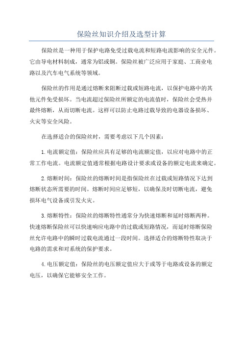
保险丝知识介绍及选型计算

保险丝知识介绍及选型计算保险丝是一种用于保护电路免受过载电流和短路电流影响的安全元件。
它由导电材料制成,通常为铝或铜。
保险丝被广泛应用于家庭、工商业电路以及汽车电气系统等领域。
保险丝的作用是通过熔断来阻断过载或短路电流,以保护电路中的其他元件免受损坏。
当电流超过保险丝所额定的电流值时,保险丝会受热并最终熔断,从而切断电流。
这样可以防止电路过载导致的电器设备损坏、火灾等安全风险。
在选择适合的保险丝时,需要考虑以下几个因素:1.电流额定值:保险丝应具有足够的电流额定值,以应对电路中的正常工作电流。
电流额定值通常根据电路设计要求或设备的额定电流来确定。
2.熔断时间:保险丝的熔断时间是指保险丝在过载或短路情况下达到熔断状态所需要的时间。
熔断时间应足够短,以确保及时切断电流,避免损坏电气设备或引发火灾。
3.熔断特性:保险丝的熔断特性通常分为快速熔断和延时熔断两种。
快速熔断保险丝可以快速响应电路中的过载或短路情况,而延时熔断保险丝允许电路中的瞬时过载电流通过一段时间。
选择适合的熔断特性取决于电路的需求和对系统的保护要求。
4.电压额定值:保险丝的电压额定值应大于或等于电路或设备的额定电压,以确保它能够安全工作。
5.安装方式:根据具体的应用情况,保险丝可以分为表面贴装型和插入式两种。
表面贴装型适用于PCB板上的自动化设备,而插入式适用于电路板上的手动或半自动生产设备。
在实际选择保险丝时,可以根据下面的公式进行计算:保险丝额定电流>=装置或电路额定电流*安全系数安全系数一般取1.25-1.5,具体取值要根据具体的应用环境和需求来决定。
例如,一些电路的额定电流为10A,安全系数取1.5,则所需的保险丝额定电流为10A*1.5=15A。
在选择保险丝时,应选择额定电流大于或等于15A的保险丝。
总之,保险丝对电路的保护至关重要,正确选择和使用保险丝可以提高电路的安全性和可靠性。
在选择保险丝时,应根据具体电路的需求和环境条件来确定保险丝的电流额定值、熔断特性、安装方式等参数。
保险丝选型手册

保险丝的应用指南目录一.保险丝的基本工作原理二.管状保险丝的分类三.选择保险丝的十个要素四.小型管状保险丝的测试要求五.小型管状保险丝的安全认证一. 保险丝的基本原理-----------------------------------------------1.结构:在电路过电流保护元件中最常用的就是小型管状保险丝,它是由两端带有金属联接端子的管体和管内的金属熔体这两大主要部份所组成的,其外壳部份的作用是支撑和联接,大多数保险丝的外型是圆柱形的,即所称为管状的;关键的功能是由内部的熔体所决定的。
2.功能:保险丝是串联在电路中的,一般要求其电阻要小(功耗要小),因此当电路正常工作时,保险丝只相当于一根导线,能够长时间稳定的使用;由于电源或外部干扰而发生电流波动时,保险丝也能承受一定范围的过载;只有当电路中出现较大的过载电流--故障或短路--时,保险丝才会动作,通过断开电流来保护电路的安全。
3.原理:保险丝通电时因电流转换的热量会使熔体的温度上升,在负载正常工作电流或允许的过载电流时,电流所产生的热量和通过熔体,壳体和周围环境所幅射,对流和传导等方式散发的热量能逐步达到平衡;如果散热速度跟不上发热时,这些热量就会在熔体上逐部积蓄,使熔体温度上升,一旦温度达到和超过熔体材料的熔点就会使它熔化,从而断开电流,起到安全保护的作用。
4.名词术语:额定电流:保险丝的公称工作电流,代号:In额定电压:保险丝的公称工作电压,代号:Un电压降:额定电流下保险丝两端的电压降,代号:Ud冷电阻:保险丝不工作时本身的电阻值,代号:Rn过载能力:保险丝能长期工作的过载电流(有些品种能在高温条件下)熔断特性:保险丝工作的性能指标--负载电流和熔断时间两者的函数关系,即时间/电流特性 (也称为安-秒特性)。
通常有两种表达方法:----熔断特性曲线:以负载电流为X座标,熔断时间为Y座标,由保险丝在不同电流负载下的平均熔断时间座标点连成的曲线。
整机保险丝选型标准

整机保险丝选型标准一、产品介绍整机保险丝作为电气设备中的重要安全保护元件,用于在电路中预先设计的故障电流超过规定值时切断电路,保护设备和人员的安全。
选型合适的整机保险丝可以确保电气设备的正常运行和避免故障事故发生。
二、选型指南1. 额定电流:根据设备的额定工作电流和负载特性,选取合适的额定电流。
保险丝的额定电流应大于设备的额定工作电流,但不应超过设备负载特性允许的最大电流。
2. 断开能力:保险丝的断开能力应足够强大,能够在故障电流超过设定值时迅速切断电路。
根据所需断开能力,选择合适的断开特性和断开时间。
3. 重复操作能力:某些电气设备需要频繁开关,因此整机保险丝应具备足够的重复操作能力,能够在多次开关中保持稳定的断开和闭合特性。
4. 安全认证:选用经过认证的整机保险丝品牌或制造商,确保产品符合国际和行业相关标准,以保证产品的质量和可靠性。
5. 特殊环境考虑:对于在特殊环境(如高温、高湿度、震动等)下工作的电气设备,应选用具有相应环境适应性的整机保险丝,并确保其性能能够长期稳定。
三、选型流程1. 了解设备功率和负载特性。
2. 根据设备额定电流选择合适的额定电流。
3. 根据断开能力要求选择合适的断开特性和断开时间。
4. 确认整机保险丝的重复操作能力是否满足需求。
5. 考虑特殊环境因素,选用相应的环境适应性保险丝。
6. 选择通过安全认证的整机保险丝品牌或制造商。
四、质量控制1. 选用符合安全标准的整机保险丝产品。
2. 确保整机保险丝与设备的电气参数匹配,不得超过额定电流使用。
3. 定期检查和维护整机保险丝,确保其正常运行。
4. 进行必要的故障分析和故障处理,及时更换损坏的整机保险丝。
5. 存放整机保险丝时,要避免高温、潮湿和震动等有损其性能的环境。
以上为整机保险丝的选型标准,仅供参考。
在选型过程中,应结合具体设备的需求以及相关法规和标准进行综合考虑,并与专业人士进行咨询和确认。
保险丝计算选型指南

10000
100000
10
Pacific Engineering Corporation
【STEP2】 决定连接电线尺寸 【STEP2】 决定连接电线尺寸 ①-1 选定连接电线尺寸
AV-20sq 完全マッチング 100secマッチング × ○
AVXf-20sq ○ ○
ห้องสมุดไป่ตู้
Pacific Engineering Corporation
13
○ ○ ○ × × × × ○ ○ ○ × × × ×
2009/4/16
慢熔保险丝
2sq 30A 40A 50A 40℃ 60A 80A 100A 一般电线 120A 30A 40A 50A 80℃ 60A 80A 100A 120A ○ × × × × × × ○ × × × × × × 3sq ○ ○ (○) × × × × ○ ○ × × × × × 5sq ○ ○ ○ ○ × × × ○ ○ ○ ○ × × × 8sq - ○ ○ ○ ○ × × - ○ ○ ○ (○) × ×
Pacific Engineering Corporation 2009/4/16 9
【参考3】
用I2t-T特性图检证保险丝寿命
殿 2005/3/15
検討回路 パルス波形 ピーク9.5A
Life prediction result
(寿命予測結果)
PACIFIC ENGINEERING CORP. R&D Department.
Pacific Engineering Corporation 2009/4/16 14
慢熔保险丝
2sq 30A 40A 50A 40℃ 60A 80A 100A 耐热电线 120A 30A 40A 50A 80℃ 60A 80A 100A 120A ○ × × × × × × ○ × × × × × × 3sq ○ ○ (○) × × × × ○ ○ (○) × × × × 5sq ○ ○ ○ ○ × × × ○ ○ ○ ○ × × × 8sq - ○ ○ ○ ○ ○ × - ○ ○ ○ ○ × ×
保险丝计算选型指南

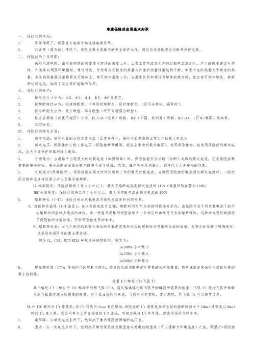
电流保险丝应用基本知识一、保险丝的作用:1、正常情况下,保险丝在电路中起连接电路作用。
2、非正常(超负载)情况下,保险丝做为电路中的安全保护元件,通过自身熔断安全切断并保护电路。
二、保险丝的工作原理:保险丝通电时,由电能转换的热量使可熔体的温度上升。
正常工作电流或允许的过载电流通过时,产生的热量通过可熔体、外壳体向周围环境辐射,通过对流、传导等方式散发的热量与产生的热量逐渐达到平衡。
如果产生的热量大于散发的热量,多余的热量就逐渐积聚在可熔体上,使可熔体温度上升;当温度达到和超过可熔体的熔点时,就会使可熔体熔化、熔断而切断电流,起到了安全保护电路的作用。
三、保险丝的分类:1、2、3、4、5、四、1、2、3、4、5、ABIn200%2分钟最大6、熔化热能值(I2T):使保险丝的熔断体熔化,部份汽化的切断电流所需要的公称能量值,简单说就是使保险丝熔断所需的最小热能值。
总量I2t=熔化I2t+飞弧I2t其中熔化I2t(相当于IEC标准中的预飞弧I2t),指从熔体熔化到飞弧开始瞬间所需要的能量;飞弧I2t是指飞弧开始瞬间到飞弧最终熄灭所需要的能量。
对于低压保险丝来说,飞弧时间非常短,常可忽略,即飞弧I2t可以按零计算。
UL和IEC都未对I2t作要求,但I2t对选用fuse有些帮助。
保险丝的I2t测算是在保险丝的熔断时间小于10ms(通常是以8ms)时的I2t来计算。
我公司样本上有各规格的I-T曲线,有相应规格I2t参考值,供选用保险丝时参考。
7、电压降:在额定电流条件下,达到热平衡后保险丝两端的电压差。
8、温升:在一定电流条件下,达到热平衡后保险丝表面温度与通电初始温度(可以理解为环境温度)之差,即温升=保险丝表面温度—环境温度。
五、保险丝管的安全标准及标志:1、UL、CSA标准:美国、加拿大等北美地区安全标准;小型电流保险丝管标准为UL248-1/14、CSA248-1/14。
安全标志:---UL/CSALIST(列名标志),完全按照UL/CSA248-1/14标准测试认证通过的产品安全标志。
- 1、下载文档前请自行甄别文档内容的完整性,平台不提供额外的编辑、内容补充、找答案等附加服务。
- 2、"仅部分预览"的文档,不可在线预览部分如存在完整性等问题,可反馈申请退款(可完整预览的文档不适用该条件!)。
- 3、如文档侵犯您的权益,请联系客服反馈,我们会尽快为您处理(人工客服工作时间:9:00-18:30)。
Fuse Selection GuideAlthough care is taken to properly design electrical and electronic circuits; overcurrents in the form of short-circuits and overload can occur. The sole purpose of fuses and circuit breakers is to protect personnel and/or equipment from serious harm when an overcurrent condition arises. This guide is intended to help create a better understanding the various parameters of overcurrent protection and the proper application of circuit protective devices. This guide creates a basic understanding of overcurrent principles and applications but is not intended to supplant sound engineering principles or replace specific application testing.OvercurrentsAn overcurrent is a condition which exists in an electrical circuit when the normal load current is exceeded. The two basic forms of an overcurrent are overloads and short circuits. Fuses and circuits breakers primary role in a circuit is to protect personnel and equipment when dangerous overcurrents do happen.Short CircuitA short-circuit is an overcurrent condition where an abnormal, low-resistance, circuitpath is introduced into the circuit. This low-resistance path bypasses the normal load and can create extremely high currents (up to 1000x the normal current under some conditions).Under normal conditions a typical circuit may be described by Ohm’s Law as follows:When a short circuit occurs, a low-resistive, abnormal path is created which will cause the circuit current to increase as the circuit resistance is decreased. The current when a short circuit is introduced can exceed 1000 times the normal current of the circuit. The circuit diagram of a short circuit is shown below:Over LoadAn overload is an overcurrent condition where the current exceeds the normal full load-capacity of the circuit but where no fault condition (short-circuit) is present. A momentary overload condition (also known as “in-rush” currents) may also occur when a circuit is first initialized due to capacitor charging and/or motor-startup. A over load circuit diagram is shown below:In order to select the proper protective device, the following parameters and criteria need to be considered:1.What is the normal operating current of the circuit?2.What is the operating voltage?3.Is the circuit AC or DC?4.What is the operating ambient temperature?5.What is the available short-circuit current?6.What is the maximum allowable I²t?7.Are there in-rush currents available?8.Is the protective device being used for short-circuit protection, over-loadprotection, or both?9.What are the physical size limitations?10. Is the PCB surface mount or thru-hole?11.Does the fuse need to be "field-replaceable"?12.Is resettability an issue?13.What safety agency approvals are needed?14.How will I mount the device?15.What are the cost considerations?What is the normal operating current of the circuit?In order to select the right amperage of the fuse, you first need to know the full-load steady-state current of the circuit at an ambient temperature of 25º C (68º F). Once the current value is determined, then a fuse rating should be selected as to be 135% of this value (taken to the next standard value).For example, if the normal steady-state current is calculated to be 10 amps, then a 15A fuse rating should be selected [10 amps x 135% = 13.5 amps, the next larger standard size is 15A].It is important to note that if the fuse is intended to be used in an environment with possibly very high or low ambient temperatures, then the nominal fuse current would need to be sized significantly higher or lower (see ambient temperature below).What is the operating voltage?The basic rule of thumb is that the voltage rating of the fuse must always higher than the voltage rating of the circuit that it is protecting.For example, if the circuit voltage is 24 volts, then the fuse voltage rating must be higher than 24 volts (yes...it can be 250 V...just so long as it’s higher than the circuit voltage). Is the circuit AC or DC?There exist two distinct types of circuits AC (alternating current) and DC (direct current).AC power is what you will typically find in your home from the electrical utility. AC power is created primarily by moving machines such as generators and delivered through the electric grid.DC power is typically used in electronic and automotive applications. DC power generally is created via a chemical reaction (as batteries and solar cells) or converted AC power through the use of AC to DC power supplies.With AC power, the current and voltage oscillate back and forth. This oscillation helps the fuse to clear quickly. DC power on the other hand doesn’t oscillate so the fuse must find other means to clear itself when opening.Because of these differences, some fuses are designed specifically to be used in DC applications (such as automotive fuses). Some AC rated fuses may be used in DC applications, however there may be a voltage de-rating in these cases.What is the operating ambient temperature?Ambient temperature is a fancy way of saying the “outside air” surrounding the fuse. Normally, the fuses are tested in "laboratory conditions" by the safety agencies such as UL and CSA. The lab conditions are almost always set at 25°C or 77°F. Unfortunately, most real world conditions are not those found in a laboratory.Fuses are heat sensitive devices meaning that it takes heat (via the overcurrent) in order to melt the fuse element inside the fuse. The more heat...the faster it takes to melt the fuse element...the less heat...the longer it takes to melt the fuse element.If a fuse will be subjected to a higher temperature than 25°C, then the fuse amperage will need to be increased as to compensate for the higher temperature (to avoid "nuisance tripping"). Likewise, if the fuse will be used at a lower temperature, then the fuse amperage needs to be lowered (or else it might never open).The rule of thumb is that for every 20°C higher or lower in temperature, the fuse should be re-rated higher or lower 10-15%.An example of a fuse re-rating when higher ambient temperatures are present:Normal full-load current:1 AmpNormal fuse sizing:1.5 Amps (135% of full load current taken to the nexthigher standard rating)Ambient Temperature: 65°CRe-rating:Re-rating: 2 Amps (130% of normal fuse rating) Conversely, when a fuse is intended to be used in extreme low temperature conditions, the fuse must have a lower rating than that in normal conditions.An example of the fuse re-rating when lower ambient temperatures are present:Normal full-load current:1 AmpNormal fuse sizing:1.5 Amps (135% of full load current taken to the nexthigher standard rating)Ambient Temperature: -15°CRe-rating:1.2 Amps (70% of normal fuse rating taken to the nexthigher standard fuse rating)What is the available short-circuit current?The available short circuit current is the measured or calculated current that can be delivered to a circuit by a power source when a short circuit is present. This information is extremely important as an overcurrent protective device has only a finite ability to safely open a circuit when a fault condition occurs. Therefore the amount of fault current available is a critical piece of information in order to select the proper protective device.The available short circuit calculation can be very complex and generally should be left to qualified engineers to calculate. These calculations are generally based on the following factors:•How much short-circuit current is available from the utility?•What is the resistance of the wiring from the utility to the piece of equipment where the fuse is installed?•What is the internal resistance of the piece of equipment where the fuse is installedOnce all of these factors are known, then the engineer can calculate the available short circuit current to the fuse.The fuse must be selected as to have a greater short circuit rating than what is available in the circuit (otherwise the fuse can explode and cause great harm to people and equipment!)What is the maximum allowable I²t?All overcurrent protective devices take a certain amount of "reaction time" when they open to clear a circuit fault. During the time it takes for the fuse to open, there is energy flowing through the fuse. That energy is measured in I²t. There two parts to the fuse’s "reaction time".1) The time it takes to melt the fuse element (also known as the melting time, T m).2) The time it takes to quench the electrical arc (also known as the arcing time, T a).The total time open the fault is known as the total clearing time. T c + T m + T aDuring this clearing time, there is energy is being "let-thru" the fuse. The downstream components are then subjected to this extreme energy as it passes through the fuse (if only for a few milliseconds).In order to specify the proper fuse or circuit breaker in a circuit, the engineer must know the withstand capabilities of the downstream circuit components and select a fuse whose let-thru energy is below that of those components.Are there "in-rush" currents available?Depending on the circuit, there are times when a large amount of current is requiredwhen a piece of equipment is turned on. The types of components that can cause this type of in-rush include motors, fans, and capacitors.The in-rush current can be as high as 6-10 times that of the normal current (for example a typical TV might draw 3A but the in-rush could be as high as 30A). These currents are typically harmless and subside within 1-2 seconds of startup.During an in-rush, the fuse should not open. The specified fuse in this case should be a time-delay fuse allowing the piece of equipment to start up properly without a nuisance opening of the fuse when the overcurrent occurs.Is the protective device being used for short-circuit protection, over-load protection, or both?If the device is to be used as short-circuit protection, the fuse or circuit breaker must interrupt the fault quickly (generally less than 4 milliseconds) in order to give the maximum protection to equipment and personnel.If the fuse or circuit breaker is intended for over-load protection only, then it can be much slower in reacting to the over-current - seconds or even minutes as compared to milliseconds...All fuses offer some form of both short-circuit protection as well as over-load protection whereas many circuit breakers however are over-load protection ONLY and have no capabilities to protect against dangerous short-circuits.What are the physical size limitations?Many times the fuse or circuit breaker needs to be mounted into a place with physical size limitations.It is this reason that fuse and circuit breaker manufacturers have created a wide selection of components with varying physical sizes. Typically however, there are a trade-offs that the engineer must consider.Generally speaking, the smaller the fuse, the less current and/or capabilities that the fuse or circuit breaker may have. For example, a subminiature fuse maybe limited to 15A where as the larger 1/4" x 1 1/4" glass tube fuse can accommodate up to 40A.Additionally, although the fuse can be smaller, the corresponding fuse holder maybe substantially bigger adding to the consideration.Is the PCB surface mount or thru-hole?There are several different options for both surface mount fuses and thru-hole fuses.With surface mounted fuses, there are multiple sizes available from a 6125 (6.1 x 2.5 mm) package all the way down to a 0603 (0.6 x 0.3 mm) package.The thru-hole options are even greater with axial-leaded options available on all of ourstandard glass and ceramic fuses as well as a variety of leaded subminiature and micro fuses.These same options are available in resettable fuses as well.Additionally, the fuse mounting can also play a part in the designers’ decision especially if the fuse needs to be field-replaceable.Does the fuse need to be "field-replaceable"?Fuses are intended to open a circuit when an overcurrent occurs; whether it be a short-circuit or an over-load. A decision by the engineer needs to be made as to whether or not the fuse should be field replaceable.The primary reason for making the fuse replaceable is simply convenience for the end-user in getting their equipment back up and running.The reasons for choosing not to have the fuse field replaceable are two-fold:1.There can be a significantly greater cost to the manufacturer to include afuseholder as opposed to directly soldering the fuse into or onto the PCB2.The manufacturer may not want the end-customer to access the interior of theequipment to replace the fuse for liability issues. This is especially true when ashort-circuit was the cause of the problem in the first place.3.The manufacturer may have some "planned obsolesce" of their parts and maywant to replace the entire circuit board rather than have someone replace just the fuseIs resettability an issue?There are one-time use fuses and resettable type fuses available to the engineer.Both types of fuses provide short-circuit and over-load protection. Resettable fuses are limited to circuit applications below 9 amps (at 12V) and even less current at higher voltages.Circuit breakers can also provide resettability and can range from 1A to 6000A.One-time fuses are just as their name implies. Once they are called upon to act, the interior link melts and the fuse must be replaced. Just because the fuse is replaced, there can still be a short-circuit or over-load still present in the circuit which can cause the newly replaced fuse to open as well. Care should be taken to correct whatever problem that may have occurred when the fuse opened in the first place...before replacing the open fuse with a new fuse.What safety agency approvals are needed?There is an entire alphabet soup of world-wide safety agencies out there. UL, CSA, IEC, CCC, PSE, VDE, Nemko, Semko and TUV are some of the most popularagencies.The agency approvals needed by manufacturers depends solely on what type of equipment they are making and where in the world they hope to sell their equipment.Fuses typically are available with several approvals (for example UL and CSA). Even within a single agency, there can be multiple types of approvals such as UL listing versus UL recognized. .Certain equipment does not require any agency approvals such as many automotive or low-voltage applications.The biggest issues as it relates to safety agency approvals for fuses is that there are several different test methodology and standards depending on the agency involved. This might mean two different fuse characteristics for what is apparently the same fuse and/or application.How will the fuse be mounted?One of the most careful considerations that need to be made is the mounting of the fuse in the circuit. There are several options at hand:1. Direct Solder - In this method, the fuse is directly soldered into or onto the printedcircuit board (PCB). The drawback to this design is the lack of field replaceable parts as discussed in great detail in section 11 but cost can be significantlyreduced with this mounting method.2. Fuse Clips - Fuse clips are relatively inexpensive and allow for fieldreplaceability. Fuseclips are typically mounted on a PCB so any attempt atreplacing the fuse will require opening of the piece of equipment by the end-user. Additionally, removing a fuse from a PCB without disconnecting the power source could lead to an electrical shock when touching the fuse. Fuse clips are available for all "tube" fuses as well as microfuses. Typically fuseclips are limited to 15A of normal current. Fuse clips are generally not listed or recognized by any safety agencies.3.Panel Mounted Fuseholders - Panel mounted fuseholders allow for easy accessfor the end-user to replace the fuse in the field. The panel mount fuseholder isshock-safe meaning that the fuse is removed safely when the cap of thefuseholder is removed preventing the possibility of electrical shocks.Fuseholders are typically tested and approved by safety agencies such as ULand CSA. Fuseholders are typically available up to 30A.4. Fuse Blocks - Fuse blocks are like fuse clips however they do not need to bemounted on the PCB. Fuses mounted in fuse blocks are typically only accessible by opening the piece of equipment which could lead to electrical shocks if theequipment is not disconnected from the power source. Fuse blocks are one ofthe few methods to mount fuses of large amperage.5.Inline Fuse Holders - Inline fuse holders are typically used as a part of a wireharness assembly or where no surface is available to secure another type of fuse mount. Inline fuse holders are generally available up to 100A in lower voltageapplications and up to 30A in higher voltage applications.What are the cost considerations?The costs considerations can vary by several degrees depending on the size, performance, and mounting of the fuse. Generally speaking, the larger a fuse is; the most it will cost (due to higher material costs to build the fuse).The performance characteristics of a particular fuse are also a large cost consideration.A low voltage automotive fuse might a fraction of the cost as compared with a 500V super high-speed, ceramic tube fuse both rated at 10A.Safety agency approvals will also add to the overall cost of the fuse.One of the largest costs of a fuse is the fuse holder. A typical panel-mount fuse holder may cost in upwards of 10 times than that of the fuse itself.。
