mstp+vrrp+ospf+策略路由实验
mstp加vrrp的实验例子
mstp加vrrp的实验例子(原创实用版)目录1.MSTP 和 VRRP 的概述2.MSTP 加 VRRP 的实验环境搭建3.实验步骤和过程4.实验结果及分析5.实验结论和展望正文一、MSTP 和 VRRP 的概述1.MSTP(Multiple Spanning Tree Protocol):多实例生成树协议,用于在多个 VLAN(虚拟局域网)之间实现生成树保护。
2.VRRP(Virtual Router Redundancy Protocol):虚拟路由器冗余协议,用于提高网络设备的可靠性和冗余性。
二、MSTP 加 VRRP 的实验环境搭建1.设备:两台路由器(Router1 和 Router2),一台交换机(Switch)2.接口:Router1 的接口 G0/0/1 和 G0/0/2 分别连接到 Switch 的接口 1 和 2;Router2 的接口 G0/0/1 和 G0/0/2 分别连接到Switch 的接口 3 和 4。
3.配置:为每个接口分配不同的 VLAN,如 G0/0/1 为 VLAN10,G0/0/2 为 VLAN20。
三、实验步骤和过程1.在 Router1 上配置 MSTP 和 VRRP:a.配置 MSTP:在 Router1 上启用 MSTP,将 G0/0/1 和 G0/0/2 分别配置为 MSTP 的实例 1 和实例 2。
b.配置 VRRP:在 Router1 上启用 VRRP,将 G0/0/1 和 G0/0/2 分别配置为 VRRP 的虚拟路由器 1 和虚拟路由器 2。
2.在 Router2 上配置 MSTP 和 VRRP:a.配置 MSTP:在 Router2 上启用 MSTP,将 G0/0/1 和 G0/0/2 分别配置为 MSTP 的实例 1 和实例 2。
b.配置 VRRP:在 Router2 上启用 VRRP,将 G0/0/1 和 G0/0/2 分别配置为 VRRP 的虚拟路由器 1 和虚拟路由器 2。
VRRP、HSRP和MSTP、SLA综合实验

SW1
SW3
pc1
Vlan10
vlan20
Vlan10
SW4 vlan20
pc2 192.168.20.100
一、 HSRP 和 VRRP 的配置
可以使用HSRP 这里先介绍HSRP 可以使用HSRP或者 HSRP或者 VRRP 来实现网关的冗余, 来实现网关的冗余, 这里先介绍HSRP的配置 HSRP的配置: 的配置:பைடு நூலகம்HSRP的配置如下 HSRP的配置如下: 的配置如下:
SW2
SW1
SW3
pc1
Vlan10
vlan20
Vlan10
SW4 vlan20
pc2 192.168.20.100
再看 R2 路由表:
很显然不管是去 vlan10 还是 vlan20 的数据都走 SW2 了,到底能不能行的通还得继续尝 试,我弱弱的估计这样应该会出问题的
果不其然,如我所料,PC2 可以通,但 PC1 无法 ping 通,问题出在哪了 原因很简单,因为上行 PC1 发出的数据包先交给 SW1,SW1 根据路由表中的提示将包 再交给 SW2,此时 SW2 一看源地址是 vlan10 网段的便果断的交还给 SW1 如此往复便出现 死循环了,自然就通不了了,但下行链路则不受影响,R2 将数据包交给 SW2,SW2 他也很
sw2 10.250 SW1
192.1.1.0/30 192.168.10.0 SW1 194.1.1.0/30 SW2
Vlan 10 ip:192.168.10.253 Vlan 20 ip:192.168.20.254 Vrrp 1 ip 192.168.10.250 Vrrp 1 priority 110 Vrrp 2 ip 192.168.20.250 Vrrp 2 priority 120 Vrrp2 preempt
VRRP(负载-备份)-mstp-dhcp-ospf-md5验证-链路聚合
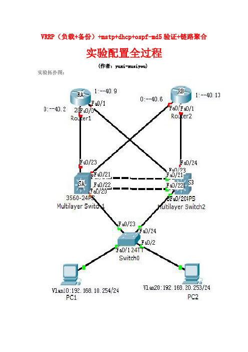
VRRP(负载+备份)+mstp+dhcp+ospf-md5验证+链路聚合实验配置全过程(作者:yuxi-xusiyou)实验拓扑图:配置过程:【RA:router ospf 1network 192.168.40.0 0.0.0.3 area 0network 192.168.40.8 0.0.0.3 area 0 OSPF的MD5验证:interface FastEthernet0/0ip address 192.168.40.2 255.255.255.252 ip ospf authentication message-digest ip ospf message-digest-key 1 md5 ccit 具体的VRRP配置:vrrp 1 ip 192.168.40.2interface FastEthernet0/1ip address 192.168.40.9 255.255.255.252 ip ospf authentication message-digest ip ospf message-digest-key 1 md5 ccit 具体的VRRP配置:vrrp 2 ip 192.168.40.13】【RB:router ospf 1network 192.168.40.4 0.0.0.3 area 0network 192.168.40.12 0.0.0.3 area 0 OSPF的MD5验证:interface FastEthernet0/0ip address 192.168.40.6 255.255.255.252 ip ospf authentication message-digest ip ospf message-digest-key 1 md5 ccit 具体的VRRP配置:vrrp 1 ip 192.168.40.2OSPF的MD5验证:interface FastEthernet0/1ip address 192.168.40.13 255.255.255.252 ip ospf authentication message-digestip ospf message-digest-key 1 md5 ccit具体的VRRP配置:vrrp 2 ip 192.168.40.13】【SA:ip routing (启用三层交换功能)router ospf 1network 192.168.10.0 0.0.0.255 area 0network 192.168.20.0 0.0.0.255 area 0network 192.168.30.0 0.0.0.255 area 0network 192.168.40.0 0.0.0.3 area 0network 192.168.40.4 0.0.0.3 area 0OSPF的md5验证:interface GigabitEthernet0/22no switchportip address 192.168.40.1 255.255.255.252 ip ospf authentication message-digestip ospf message-digest-key 1 md5 ccitinterface GigabitEthernet0/24no switchportip address 192.168.40.5 255.255.255.252 ip ospf authentication message-digestip ospf message-digest-key 1 md5 ccit配置VRRP实现冗余备份:interface Vlan10ip address 192.168.10.254 255.255.255.0 standby 1 ip 192.168.10.251interface Vlan20ip address 192.168.20.254 255.255.255.0 standby 1 ip 192.168.20.251interface Vlan30ip address 192.168.30.254 255.255.255.0 standby 1 ip 192.168.30.251【若要实现负载分担的同时,实现备份,则:Standby 1 ip 192.168.11.251 priorty 10 Standby 2 ip 192.168.20.251 priorty 100Standby 3 ip 192.168.30.251 】链路聚合:创建聚合:1,并封装为trunk端口类型:interface Port-channel1switchport trunk encapsulation dot1qswitchport mode trunk(注:几乎所有的三层交换机在封装trunk类型端口是都须添加switchport trunk encapsulation dot1q 命令)进入接口模式,封装trunk端口,并加入聚合组1:interface GigabitEthernet0/20switchport trunk encapsulation dot1qswitchport mode trunkspeed 100duplex fullchannel-group 1 mode oninterface GigabitEthernet0/21switchport trunk encapsulation dot1qswitchport mode trunkspeed 100duplex fullchannel-group 1 mode on(注:添加局和端口时必须要设定speed 100 最大速度,duplex full 全双工模式)设置f0/23为trunk端口类型:interface GigabitEthernet0/23switchport trunk encapsulation dot1qswitchport mode trunk在交换机上启用dhcp服务,使得SwitchA为vlan 10提供动态ip 地址:service dhcpip dhcp excluded-address 192.168.10.250 192.168.10.254ip dhcp pool vlan10network 192.168.10.0 255.255.255.0default-router 192.168.10.251配置实例10、20,并分别添加vlan 10和vlan 20;实现负载分担和备份功能,使得vlan10的数据以SA为主路线。
VRRP+MSTP配置案例

H3C 7503-A<SwitchA> system-view[SwitchA] bfd echo-source-ip 11.11.11.11[SwitchA]vlan 10 20 30 40 50 60 70 80 90 4094[SwitchA] interface GigabitEthernet2[SwitchA-GigabitEthernet2] port link-type trunk[SwitchA-GigabitEthernet2] port trunk permit vlan 10 to 90[SwitchA] interface GigabitEthernet3[SwitchA-GigabitEthernet3] port link-type trunk[SwitchA-GigabitEthernet3] port trunk permit vlan 10 to 90[SwitchA] interface vlan-interface 4094[SwitchA-Vlan-interface4094] ip address 192.168.100.254 24[SwitchA] interface vlan-interface 10[SwitchA-Vlan-interface10] ip address 192.168.10.1 24[SwitchA-Vlan-interface10] vrrp vrid 10 virtual-ip 192.168.10.254 24[SwitchA-Vlan-interface10] vrrp vrid 10 priority 120[SwitchA-Vlan-interface10] vrrp vrid 10 track interface Vlan-interface4094 reduced 255 [SwitchA-Vlan-interface10]quit[SwitchA] interface vlan-interface 20[SwitchA-Vlan-interface20] ip address 192.168.20.1 24[SwitchA-Vlan-interface20] vrrp vrid 20 virtual-ip 192.168.20.254 24[SwitchA-Vlan-interface20] vrrp vrid 20 priority 120[SwitchA-Vlan-interface20] vrrp vrid 20 track interface Vlan-interface4094 reduced 255 [SwitchA-Vlan-interface20]quit[SwitchA] interface vlan-interface 30[SwitchA-Vlan-interface30] ip address 192.168.30.1 24[SwitchA-Vlan-interface30] vrrp vrid 30 virtual-ip 192.168.30.254 24[SwitchA-Vlan-interface30] vrrp vrid 30 priority 120[SwitchA-Vlan-interface30] vrrp vrid 30 track interface Vlan-interface4094 reduced 255 [SwitchA-Vlan-interface30]quit[SwitchA] interface vlan-interface 40[SwitchA-Vlan-interface40] ip address 192.168.40.1 24[SwitchA-Vlan-interface40] vrrp vrid 40 virtual-ip 192.168.40.254 24[SwitchA-Vlan-interface40] vrrp vrid 40 track 1 switchover[SwitchA-Vlan-interface40] bfd min-echo-receive-interval 10[SwitchA-Vlan-interface40] bfd detect-multiplier 3[SwitchA-Vlan-interface40]quit[SwitchA] interface vlan-interface 50[SwitchA-Vlan-interface50] ip address 192.168.50.1 24[SwitchA-Vlan-interface50] vrrp vrid 50 virtual-ip 192.168.50.254 24[SwitchA-Vlan-interface50] vrrp vrid 50 track 1 switchover[SwitchA-Vlan-interface50] bfd min-echo-receive-interval 10[SwitchA-Vlan-interface50] bfd detect-multiplier 3[SwitchA-Vlan-interface50] quit[SwitchA] interface vlan-interface 60[SwitchA-Vlan-interface60] ip address 192.168.60.1 24[SwitchA-Vlan-interface60] vrrp vrid 60 virtual-ip 192.168.60.254 24[SwitchA-Vlan-interface60] vrrp vrid 60 track 1 switchover[SwitchA-Vlan-interface60] bfd min-echo-receive-interval 10[SwitchA-Vlan-interface60] bfd detect-multiplier 3[SwitchA-Vlan-interface60] quit[SwitchA] interface vlan-interface 70[SwitchA-Vlan-interface70] ip address 192.168.70.1 24[SwitchA-Vlan-interface70] vrrp vrid 70 virtual-ip 192.168.70.254 24[SwitchA-Vlan-interface70] vrrp vrid 70 track 1 switchover[SwitchA-Vlan-interface70] bfd min-echo-receive-interval 10[SwitchA-Vlan-interface70] bfd detect-multiplier 3[SwitchA-Vlan-interface70] quit[SwitchA] interface vlan-interface 80[SwitchA-Vlan-interface80] ip address 192.168.80.1 24[SwitchA-Vlan-interface80] vrrp vrid 80 virtual-ip 192.168.80.254 24[SwitchA-Vlan-interface80] vrrp vrid 80 track 1 switchover[SwitchA-Vlan-interface80] bfd min-echo-receive-interval 10[SwitchA-Vlan-interface80] bfd detect-multiplier 3[SwitchA-Vlan-interface80] quit[SwitchA] interface vlan-interface 90[SwitchA-Vlan-interface90] ip address 192.168.90.1 24[SwitchA-Vlan-interface90] vrrp vrid 90 virtual-ip 192.168.90.254 24[SwitchA-Vlan-interface90] vrrp vrid 90 track 1 switchover[SwitchA-Vlan-interface90] bfd min-echo-receive-interval 10[SwitchA-Vlan-interface90] bfd detect-multiplier 3[SwitchA-Vlan-interface90] quit[SwitchA] track 1 bfd echo interface vlan-interface 10 to 90 remote ip 11.0.0.3 local ip 11.0.0.2[SwitchA] stp region-configuration[SwitchA-mst-region] region-name vrrp[SwitchA-mst-region] instance 1 vlan 10 20 30[SwitchA-mst-region] instance 2 vlan 40 50 60[SwitchA-mst-region] instance 3 vlan 70 80 90[SwitchA-mst-region] active region-configuration[SwitchA-mst-region] quit[SwitchA] stp instance 1 root primary[SwitchA] stp instance 2 root secondary[SwitchA] stp instance 3 root secondary[SwitchA] stp enable[SwitchA] port Gigabitethernet 6[SwitchA-GigabitEthernet6] port link-type trunk[SwitchA-GigabitEthernet6] port trunk permit vlan 10 20 30[SwitchA] port Gigabitethernet 5[SwitchA-GigabitEthernet5] port link-type trunk[SwitchA-GigabitEthernet5] port trunk permit vlan 40 50 60[SwitchA] port Gigabitethernet 4[SwitchA-GigabitEthernet4] port link-type trunk[SwitchA-GigabitEthernet4] port trunk permit vlan 70 80 90[SwitchA] port Gigabitethernet 1[SwitchA-GigabitEthernet1] port access vlan 4094[SwitchA-GigabitEthernet1] stp disable[SwitchA]ip route-static 0.0.0.0 0.0.0.0 192.168.100.100 preference 60 //内部所有主机访问外网的下一跳地址为上联设备接口地址H3C 7503-B<SwitchA> system-view[SwitchA] bfd echo-source-ip 11.11.11.11[SwitchA]vlan 10 20 30 40 50 60 70 80 90 4094[SwitchA] interface GigabitEthernet2[SwitchA-GigabitEthernet2] port link-type trunk[SwitchA-GigabitEthernet2] port trunk permit vlan 10 to 90[SwitchA] interface GigabitEthernet3[SwitchA-GigabitEthernet3] port link-type trunk[SwitchA-GigabitEthernet3] port trunk permit vlan 10 to 90[SwitchA] interface vlan-interface 4094[SwitchA-Vlan-interface4094] ip address 192.168.100.253 24。
校园网双核心(MSTP+VRRP)的拓扑实现和配置实例

VRRP技术概述(cont.)
VRRP是一种容错协议,它保证当主机的下一跳路由器失 效时,可以及时的由另一台路由器来替代,从而保持通讯 的连续性和可靠性。 为了使VRRP工作,要在路由器上配置虚拟路由器号和虚 拟IP地址,同时会产生一个虚拟MAC(00-00-5E-00-01[VRID])地址,这样在这个网络中就加入了一个虚拟路由 器。 一个虚拟路由器由一个主路由器和若干个备份路由器组成, 主路由器实现真正的转发功能。当主路由器出现故障时, 一个备份路由器将成为新的主路由器,接替它的工作。
VRRP组规划
表三 VRRP组规划 组规划 用途 生产用户VLAN 生产用户VLAN OA用户 用户VLAN 用户 OA服务器 服务器VLAN 服务器 视频会议VLAN 视频会议 交换机管理VLAN 交换机管理 互连网段VLAN 互连网段 VRRP组地址 1-10 11-20 21-30 31-40 99 100
!将vlan10、30放入实例1中 每个实例都会生成一个独立的生成树
RG-S21A(config-mst)#revision 1 !配置多生成树的版本号 RG-S21A(config-mst)#instance 2 vlan 20,40
!将vlan20、40放入实例2中
RG-S21A(config-mst)#revision 1 RG-S21A(config-mst)#exit
A vlan1ห้องสมุดไป่ตู้
CST
C vlan2
MST region 1
MST region 2 vlan2
vlan1 B D
提纲
MSTP技术概述 VRRP技术概述 校园网双核心(MSTP+VRRP)的拓扑实现 校园网双核心(MSTP+VRRP)的配置实例 MSTP+VRRP 注意事项
自己做的关于vrrp,mst功能

拓扑图:路由器和三层交换机通过网络层传输品字形连接,三层交换机和二层交换机通过链路层传输交叉连接。
路由器与外网通过串口连接。
配置:R4:外网只配置时钟速率和ip地址。
不加任何路由条目,与现实环境中相符。
R1:配置IP地址配置NAT,将内网所有IP全部转换成预设公网IP(123.123.123.123)内网中的不同网络号均变成不同端口号,因此一个公网IP就可以保证所有主机均可以与外网相连。
配置OSPF协议,与三层交换机路由条目动态联系,并且可以快速确定各设备是否出现问题。
一条默认路由指向外网,并且通过ospf传递给自治域内的设备。
设置该路由器为DR,域内设备管理信息传输通过该路由器。
SW31&SW32:配置IP地址f0/4设置成三层端口与路由器相连在172.16.1.0网段四个vlan都分别设置网段,方便管理、制定策略。
配置vrrp虚拟路由器冗余协议使得两个设备在逻辑上成为一个设备并使用.254地址。
根据优先级不同,不同vlan的包通过的交换机不同,奇数vlan会通过sw1传到外网,偶数vlan则通过sw2。
而当任意一个设备出现问题时,包会自动传给另一个路由器,修好后自动恢复。
下层交换机间使用多生成树(multiple spanning tree)协议,把奇数vlan和偶数vlan分成两个组,根据分组不同拓扑图会不同,防止形成环造成广播风暴。
两台机器间用以太通道链接,保证高速高可靠性。
SW21&SW22:划分vlan,并把端口划入vlan中使用多生成树功能介绍:这个拓扑中比较复杂的技术为:vrrp,MST,NA T。
1.VRRP功能介绍:虚拟路由器冗余协议(VRRP)是一种选择协议,它可以把一个虚拟路由器的责任动态分配到局域网上的VRRP 路由器中的一台。
控制虚拟路由器IP 地址的VRRP 路由器称为主路由器,它负责转发数据包到这些虚拟IP 地址。
一旦主路由器不可用,这种选择过程就提供了动态的故障转移机制,这就允许虚拟路由器的IP 地址可以作为终端主机的默认第一跳路由器。
mstp加vrrp的实验例子

mstp加vrrp的实验例子(最新版)目录1.实验背景2.实验目的3.实验环境与工具4.实验步骤5.实验结果与分析6.实验结论正文1.实验背景随着科技的发展,虚拟现实技术 (Virtual Reality, VR) 已经被广泛应用在各个领域,如教育、医疗、游戏等。
VR 技术通过计算机模拟生成一个三维虚拟世界,用户可以在其中进行实时、交互式的操作。
为了提高 VR 技术的实用性和沉浸感,许多研究者开始探索如何将 VR 技术与空间定位技术 (Simultaneous Localization and Mapping, SLAM) 相结合。
在这样的背景下,本实验将探讨如何使用 MSTP(MonoSLAM)加 VRRP(VR Robot Positioning)的方法来进行空间定位和导航。
2.实验目的本实验的主要目的是验证 MSTP 加 VRRP 的方法在空间定位和导航方面的准确性和实用性。
通过比较不同的定位和导航算法,找出在 VR 环境下表现最佳的方法,为未来的 VR 应用提供技术支持。
3.实验环境与工具实验环境:计算机实验室实验设备:电脑、VR 头盔、传感器实验软件:MSTP、VRRP4.实验步骤(1)搭建实验环境:将 VR 头盔与电脑连接,启动 MSTP 和 VRRP 软件。
(2)设定实验参数:设置 MSTP 的定位精度、VRRP 的导航精度等参数。
(3)进行实验:分别使用 MSTP、VRRP 及其他算法进行定位和导航实验,记录实验结果。
(4)数据分析:对比不同算法的定位精度、导航速度等指标,分析实验结果。
5.实验结果与分析经过多次实验对比,MSTP 加 VRRP 的组合在定位精度和导航速度方面表现最佳。
与其他算法相比,MSTP 能够实现较高的定位精度,而 VRRP 在导航方面具有较快的速度。
这说明 MSTP 加 VRRP 的方法在 VR 环境下具有较高的实用性。
6.实验结论通过本次实验,我们验证了 MSTP 加 VRRP 的方法在空间定位和导航方面的准确性和实用性。
VRRP+MSTP+OSPF实验

VRRP+MSTP+OSPF实验VRRP+MSTP实验要求:1.client1属于VLAN2(192.168.1.1/24)client2属于VLAN3 (192.168.2.1/24)2.SW1SW2 SW3运行MSTP+VRRP,SW1作为1.0的根桥(同时作为网关VRRP为MASTER)SW2作为2.0 的根桥(同时作为网关VRRP为MASTER)3.SW1SW2之间链路聚合4.用R1的两个环回口模拟OABOSS服务器IP分别为1.1.1.1,2.2.2.25.client1选择SW1到OABOSS ,client2选择SW2到OABOSS6.SW1SW2 AR1之间运行OSPF协议7.在AR1上起两个环回口模拟OABOSS服务器8.CLIENT1和CLIENT2能相互通信并且二者都可以和OABOSS服务器通信配置如下:AR1:interface GigabitEthernet0/0/0ip address 172.16.1.2 255.255.255.0#interface GigabitEthernet0/0/1ip address 172.16.2.2 255.255.255.0#interface LoopBack0ip address 1.1.1.1 255.255.255.255//模拟OA网#interface LoopBack1ip address 2.2.2.2 255.255.255.255//模拟BOSS网# ospf 1area 0.0.0.0network 1.1.1.1 0.0.0.0network 2.2.2.2 0.0.0.0network 172.16.1.2 0.0.0.0network 172.16.2.2 0.0.0.0#SW1:vlan batch 2 to 3 20#stp instance 1 root primarystp instance 2 root secondary#stp region-configurationregion-name xxinstance 1 vlan 2instance 2 vlan 3active region-configuration#interface Vlanif2ip address 192.168.1.251 255.255.255.0 vrrpvrid 1 virtual-ip 192.168.1.254 vrrpvrid 1 priority 120#interface Vlanif3ip address 192.168.2.251 255.255.255.0 vrrpvrid 2 virtual-ip 192.168.2.254#interface Vlanif20ip address 172.16.1.1 255.255.255.0#interface Eth-Trunk0port link-type trunkport trunk allow-pass vlan 2 to 3#interface GigabitEthernet0/0/1port link-type accessport default vlan 20#interface GigabitEthernet0/0/2port link-type trunkport trunk allow-pass vlan 2 to 3#interface GigabitEthernet0/0/23eth-trunk 0#interface GigabitEthernet0/0/24eth-trunk 0#interface NULL0#ospf 1area 0.0.0.0network 192.168.1.251 0.0.0.0network 192.168.2.251 0.0.0.0network 172.16.1.1 0.0.0.0#SW2:vlan batch 2 to 3 30#stp instance 1 root secondarystp instance 2 root primary#stp region-configurationregion-name xxinstance 1 vlan 2instance 2 vlan 3active region-configuration#interface Vlanif2ip address 192.168.1.252 255.255.255.0 vrrpvrid 1 virtual-ip 192.168.1.254#interface Vlanif3ip address 192.168.2.252 255.255.255.0 vrrpvrid 2 virtual-ip 192.168.2.254 vrrpvrid 2 priority 120#interface Vlanif30ip address 172.16.2.1 255.255.255.0 #interface Eth-Trunk0port link-type trunkport trunk allow-pass vlan 2 to 3 #interface GigabitEthernet0/0/1 port link-type accessport default vlan 30#interface GigabitEthernet0/0/2#interface GigabitEthernet0/0/3 port link-type trunkport trunk allow-pass vlan 2 to 3 #interface GigabitEthernet0/0/23 eth-trunk 0#interface GigabitEthernet0/0/24 eth-trunk 0#ospf 1area 0.0.0.0network 192.168.1.252 0.0.0.0 network 192.168.2.252 0.0.0.0 network 172.16.2.1 0.0.0.0#SW3:vlan batch 2 to 3#stp converge fast#stp region-configuration region-name xxinstance 1 vlan 2instance 2 vlan 3active region-configuration#interface GigabitEthernet0/0/1 port link-type accessport default vlan 2stp edged-port enable#interface GigabitEthernet0/0/2 port link-type trunkport trunk allow-pass vlan 2 to 3 stp instance 2 cost 200000#interface GigabitEthernet0/0/3 port link-type trunkport trunk allow-pass vlan 2 to3 stp instance 1 cost 200000#interface GigabitEthernet0/0/4 port link-type accessport default vlan 3stp edged-port enable#disstp bMSTID Port Role STP State Protection0 GigabitEthernet0/0/1 DESI FORWARDING NONE 0 GigabitEthernet0/0/2 ROOT FORWARDING NONE 0 GigabitEthernet0/0/3 ALTE DISCARDING NONE0 GigabitEthernet0/0/4 DESI FORWARDING NONE1 GigabitEthernet0/0/1 DESI FORWARDING NONE 1 GigabitEthernet0/0/2 ROOT FORWARDING NONE1 GigabitEthernet0/0/3 ALTE DISCARDING NONE2 GigabitEthernet0/0/2 ALTE DISCARDING NONE 2 GigabitEthernet0/0/3 ROOT FORWARDING NONE 2 GigabitEthernet0/0/4 DESI FORWARDING NONE。
- 1、下载文档前请自行甄别文档内容的完整性,平台不提供额外的编辑、内容补充、找答案等附加服务。
- 2、"仅部分预览"的文档,不可在线预览部分如存在完整性等问题,可反馈申请退款(可完整预览的文档不适用该条件!)。
- 3、如文档侵犯您的权益,请联系客服反馈,我们会尽快为您处理(人工客服工作时间:9:00-18:30)。
hostname s1!route-map ruijie permit 10match ip address 10set ip next-hop 192.168.100.4 !route-map ruijie permit 20match ip address 20set ip next-hop 192.168.100.5 !vlan 1!vlan 10!vlan 20vlan 100!!ip access-list standard 1010 permit 192.168.10.0 0.0.0.255 !!ip access-list standard 2010 permit 192.168.20.0 0.0.0.255 !!!spanning-treespanning-tree mst configurationinstance 0 vlan 1-9, 11-19, 21-4094 instance 10 vlan 10instance 20 vlan 20spanning-tree mst 10 priority 4096 spanning-tree mst 20 priority 8192 interface FastEthernet 0/1switchport access vlan 100!interface FastEthernet 0/2switchport access vlan 100!interface FastEthernet 0/3!interface FastEthernet 0/4interface FastEthernet 0/5!interface FastEthernet 0/6!interface FastEthernet 0/7!interface FastEthernet 0/8!interface FastEthernet 0/9!interface FastEthernet 0/10port-group 1!interface FastEthernet 0/11port-group 1!interface FastEthernet 0/12!interface FastEthernet 0/13!interface FastEthernet 0/14!interface FastEthernet 0/15interface FastEthernet 0/16!interface FastEthernet 0/17!interface FastEthernet 0/18!interface FastEthernet 0/19!interface FastEthernet 0/20!interface FastEthernet 0/21!interface FastEthernet 0/22!interface FastEthernet 0/23!interface FastEthernet 0/24switchport mode trunk!interface GigabitEthernet 0/25!interface GigabitEthernet 0/26!interface GigabitEthernet 0/27!interface GigabitEthernet 0/28!interface AggregatePort 1switchport mode trunk!interface VLAN 10no ip proxy-arpip address 192.168.10.252 255.255.255.0 vrrp 10 priority 120vrrp 10 ip 192.168.10.254!interface VLAN 20no ip proxy-arpip address 192.168.20.252 255.255.255.0 vrrp 20 ip 192.168.20.254!interface VLAN 100ip policy route-map ruijieno ip proxy-arpip address 192.168.100.1 255.255.255.0 !!router ospf 1network 192.168.10.0 0.0.0.255 area 0 network 192.168.20.0 0.0.0.255 area 0 network 192.168.100.0 0.0.0.255 area 0 !!!!line con 0line vty 0 4login!!end!hostname s2!!!!route-map ruijie permit 10match ip address 10set ip next-hop 192.168.101.5!route-map ruijie permit 20match ip address 20set ip next-hop 192.168.101.4!vlan 1!vlan 10!vlan 20vlan 100vlan 101!!no service password-encryption!!ip access-list standard 1010 permit 192.168.10.0 0.0.0.255 !!ip access-list standard 2010 permit 192.168.20.0 0.0.0.255 !!!spanning-treespanning-tree mst configurationinstance 0 vlan 1-9, 11-19, 21-4094 instance 10 vlan 10instance 20 vlan 20spanning-tree mst 10 priority 8192 spanning-tree mst 20 priority 4096 interface FastEthernet 0/1switchport access vlan 101!interface FastEthernet 0/2switchport access vlan 101!interface FastEthernet 0/3interface FastEthernet 0/4!interface FastEthernet 0/5!interface FastEthernet 0/6!interface FastEthernet 0/7!interface FastEthernet 0/8!interface FastEthernet 0/9!interface FastEthernet 0/10port-group 1interface FastEthernet 0/11port-group 1!interface FastEthernet 0/12!interface FastEthernet 0/13!interface FastEthernet 0/14interface FastEthernet 0/15!interface FastEthernet 0/16!interface FastEthernet 0/17!interface FastEthernet 0/18!interface FastEthernet 0/19!interface FastEthernet 0/20!interface FastEthernet 0/21!interface FastEthernet 0/22!interface FastEthernet 0/23!interface FastEthernet 0/24switchport mode trunk!interface GigabitEthernet 0/25!interface GigabitEthernet 0/26!interface GigabitEthernet 0/27!interface GigabitEthernet 0/28!interface AggregatePort 1switchport mode trunk!interface VLAN 10no ip proxy-arpip address 192.168.10.253 255.255.255.0vrrp 10 ip 192.168.10.254!interface VLAN 20no ip proxy-arpip address 192.168.20.253 255.255.255.0 vrrp 20 priority 120vrrp 20 ip 192.168.20.254!interface VLAN 100no ip proxy-arpshutdown!interface VLAN 101ip policy route-map ruijieno ip proxy-arpip address 192.168.101.1 255.255.255.0 !!!!!!!router ospf 1network 192.168.10.0 0.0.0.255 area 0 network 192.168.20.0 0.0.0.255 area 0 network 192.168.101.0 0.0.0.255 area 0 !!!!line con 0line vty 0 4login!!endhostname s3!!vlan 1!vlan 10!vlan 20!!spanning-treespanning-tree mst configurationinstance 0 vlan 1-9, 11-19, 21-4094 instance 10 vlan 10instance 20 vlan 20interface FastEthernet 0/1switchport access vlan 10!interface FastEthernet 0/2switchport access vlan 10!interface FastEthernet 0/3switchport access vlan 10!interface FastEthernet 0/4switchport access vlan 10!interface FastEthernet 0/5switchport access vlan 10!interface FastEthernet 0/6switchport access vlan 10!interface FastEthernet 0/7 switchport access vlan 10!interface FastEthernet 0/8switchport access vlan 10!interface FastEthernet 0/9switchport access vlan 10!interface FastEthernet 0/10switchport access vlan 10!interface FastEthernet 0/11 switchport access vlan 20 !interface FastEthernet 0/12 switchport access vlan 20 !interface FastEthernet 0/13 switchport access vlan 20 !interface FastEthernet 0/14 switchport access vlan 20 !interface FastEthernet 0/15 switchport access vlan 20 !interface FastEthernet 0/16 switchport access vlan 20 !interface FastEthernet 0/17 switchport access vlan 20 !interface FastEthernet 0/18 switchport access vlan 20 !interface FastEthernet 0/19 switchport access vlan 20 !interface FastEthernet 0/20 switchport access vlan 20 !interface FastEthernet 0/21 !interface FastEthernet 0/22 !interface FastEthernet 0/23 switchport mode trunk!interface FastEthernet 0/24 switchport mode trunk!!hostname R1!!!!interface FastEthernet 0/0ip address 192.168.100.2 255.255.255.0 vrrp 1 priority 120vrrp 1 ip 192.168.100.4vrrp 2 ip 192.168.100.5duplex autospeed auto!interface FastEthernet 0/1ip address 192.168.101.2 255.255.255.0 vrrp 1 ip 192.168.101.4vrrp 2 priority 120vrrp 2 ip 192.168.101.5duplex autospeed auto!interface FastEthernet 0/2ip address 1.1.1.1 255.255.255.0duplex autospeed auto!!!!router ospf 1network 1.1.1.0 0.0.0.255 area 0network 192.168.100.0 0.0.0.255 area 0 network 192.168.101.0 0.0.0.255 area 0 !!ref parameter 50 400!!endR1#hostname R2!!!interface FastEthernet 0/0ip address 192.168.101.3 255.255.255.0 vrrp 1 priority 120vrrp 1 ip 192.168.101.4vrrp 2 ip 192.168.101.5duplex autospeed auto!interface FastEthernet 0/1ip address 192.168.100.3 255.255.255.0 vrrp 1 ip 192.168.100.4vrrp 2 priority 120vrrp 2 ip 192.168.100.5duplex autospeed auto!interface FastEthernet 0/2ip address 1.1.1.1 255.255.255.0duplex autospeed auto!!!!router ospf 1network 1.1.1.0 0.0.0.255 area 0network 192.168.100.0 0.0.0.255 area 0 network 192.168.101.0 0.0.0.255 area 0 !!!!ref parameter 50 400 line con 0line aux 0line vty 0 4login!!endR2#。