活性炭介绍(英文版)
活性炭 activated carbon

活性炭activated carbon是一种黑色粉状,粒状或丸状的无定形具有多孔的碳,主要成分为碳,还含少量氧、氢、硫、氮、氯。
也具有石墨那样的精细结构,只是晶粒较小,层层间不规则堆积。
具有较大的表面积(500~1000米2/克),有很强的吸附性能,能在它的表面上吸附气体、液体或胶态固体;对于气体、液体,吸附物质的质量可接近于活性炭本身的质量。
其吸附作用具有选择性,非极性物质比极性物质更易于吸附。
在同一系列物质中,沸点越高的物质越容易被吸附,压强越大温度越低浓度越大,吸附量越大。
反之,减压,升温有利于气体的解吸。
常用于气体的吸附、分离和提纯,溶剂的回收,糖液、油脂、甘油、药物的脱色剂,饮用水及冰箱的除臭剂,防毒面具中的滤毒剂,还可用作催化剂或金属盐催化剂的载体。
早期生产活性炭的原料为木材、硬果壳或兽骨,后来主要采用煤,经干馏、活化处理后得到活性碳生产方法有:①蒸汽、气体活化法。
利用水蒸气或二氧化碳在850~900℃将碳活化。
②化学活化法。
利用活化剂放出的气体,或用活化剂浸渍原料,在高温处理后都可得到活性炭。
活性炭具有微晶结构,微晶排列完全不规则,晶体中有微孔(半径小于20[埃]=10-10米)、过渡孔(半径20~1000)、大孔(半径1000~100000),使它具有很大的内表面,比表面积为500~1700米2/克。
这决定了活性炭具有良好的吸附性,可以吸附废水和废气中的金属离子、有害气体、有机污染物、色素等。
工业上应用活性炭还要求机械强度大、耐磨性能好,它的结构力求稳定,吸附所需能量小,以有利于再生。
活性炭用于油脂、饮料、食品、饮用水的脱色、脱味,气体分离、溶剂回收和空气调节,用作催化剂载体和防毒面具的吸附剂。
物理特性:活性炭是一种多孔径的炭化物,有极丰富的孔隙构造,具有良好的吸附特性,它的吸附作用藉物理及化学的吸咐力而成的,其外观色泽呈黑色。
其成份除了主要的炭以外,还包含了少量的氢、氮、氧,其结构则外形似以一个六边形,由于不规则的六边形结构,确定了其多也体枳及高表面积的特点,每克的活性炭所具的有比表面相当于1000个平方米之多。
活性炭的介绍(英文)

New Developments inActivated CarbonsJan van den DikkenbergNorit Activated CarbonThe topics•What is Activated Carbon?•New Developments in Activated Carbons(AC)–Catalytic GAC in water treatment–Anaerobic groundwater treatment–WFD, municipal wastewater–WFD, 1-STEP ©filter–Water reuseWhat is Activated Carbon ?Highly porous carbonaceous adsorbentHigh surface area1 teaspoon of carbon (5 g) hasthe same surface area asa football field (≈1000 m²/g)Raw Materials Used for Norit Activated CarbonsLignitePeatCoalCoconut shellsWoodOlive stonesParticle sizes and shapesPowdered (PAC)D50: 10-50 µmDifferentfiltration rates Granular(GAC)Broken0.25-5 mm(4-50 mesh)Granular(GAC)ExtrudedDiameter0.8-4 mmMicro pores< 1 nmMeso pores1-25 nmMacro pores> 25 nmAdsorption procesDriving force•Target compounds: hydrophobic, dissolved organics, typically not or poorly biodegradable•Examples: (halogenated) aromatics, chlorinated solvents, dissolved oil, PAH, non-biodegradable COD, AOX, colour, DOC•Concentration level: relatively low (polishing)The position of AC in water treatment ApplicationsxAquarium water xPoint of Use water x x Pool water x x Waste water xUltra-Pure water xSteam condensate xBeverage Industry x x Potable water PACGACNew DevelopmentsClick here and type text•First level•First level–Second level–Second levelCatalytic GAC in water treatmentClick•First level•First level–Courtesy PWNCatalytic GAC in water treatment Process outlineHeemskerkPre-treatment Surface water H2O2/UVCatalytic GACNorit ROW 2 CATInfiltrationAnaerobic groundwater treatment–Courtesy Van Der Hoeven KliniekAnaerobic groundwater treatment Process outlineUtrechtAnaerobic extractionSolvents adsorptionNRS CARBON EA 0.5-1.5AnaerobicinfiltrationWFDWFDThe role of AC?•Natural and synthetic hormones•Detergents (Alkyl phenols)•Plasticizers (Phthalates)•PAH•Pesticides and herbicides•Medicine residualsThe Swindon ProjectIntroduction•Demonstration project for advanced wastewater treatment •GAC filters in operation since Feb 2008•Once exhausted the carbon is due for reactivation at our Purton thermal reactivation plantProcess Outline SwindonPost-clarificationCarbon adsorptionNorit GAC 830 TWSDischargeinto river RayActive sludgePre-clarificationThe Swindon ProjectMain compounds monitored •Oestrone(E1)•17β-Oestradiol(E2)•17α-Ethinyloestradiol(EE2)•Treatment objective–E1/3 +E2/1 + EE2/0.1 < 1 ng/l(E2eq.)The Swindon ProjectIndicative GAC influent•E2eq. 1-10 ng/l•COD 20 mg/l•NO3¯40-60 mg/l•Tot P 0.05-0.15 mg/lThe Swindon Project Construction ofthe adsorbersCarbon fillingFull scaleThe Swindon ProjectFull scaleACT Lab PerformanceCarbon performance00.511.522.550001000015000Bedvolumes (n)C o m p u n d l e v e l (µg /l )Influent level 17α-Ethynil Estradiol AtrazineWFD, 1-STEP ©filterAll in one filterEnhanced coagulationOne -filter conceptBiologyAdsorptionWFD, 1-STEP ©filter Process outlineHorstermeerWWTW effluent 1-STEP ©Dischargeinto environmentWFD, 1-STEP ©filterOne Step Total Effluent Polishing = 1-STEP ©•Elimination in one filter of–Nitrogen and Phosphorus–Suspended solids–Organic micro-pollutants–Heavy metals•3 treatment concepts in one filter–Enhanced coagulation, flocculation and filtration–Biological activity–Adsorption on GACWFD, 1-STEP ©filterEffl.Washwater outBackwash in (filtrate)CoagulantC-sourceNTUNO3-NPO4-PNTUNO3-N PO4-PP-totbufferbufferWFD, 1-STEP ©filterPilot UnitWFD, 1-STEP ©filterPhosphorus removal•First level•First level–Second level–Second levelWFD, 1-STEP ©filterNitrate removal•First level•First level–Second level–Second levelWFD, 1-STEP ©filterRemoval of medicine residuals•First level•First level–Second level–Second levelWFD, 1-STEP ©filterProcess outlineWWTW effluent 1-STEP ©Dischargeinto environmentRe-useoptionsWFDSummary of developments and research needs;•Full scale applications and practical experience from pilotstudies•New technology developments;–Combination of PAC and MBR technology–Multi-functional GAC filtration•Modeling of adsorption behavior–Including isotherm databaseRe-use of municipal waste water Process outlineEmmen/SchoonebeekWWTW effluentBACF UF2 stage RO EDIHeat/Power Co-generationBACFGAC surface colonization •First level•First level–Second level–Second levelRe-use of municipal waste waterClick here and type text•First level•First level–Courtesy NieuWaterSummaryNorit Activated Carbon•The multi-purpose adsorbent•Many new developments in water applicationsNo doubts. Norit. Just proof.。
活性炭
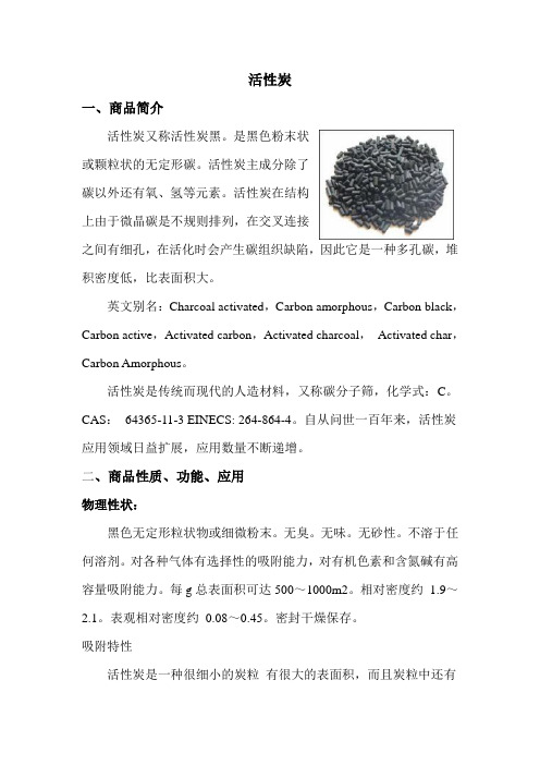
活性炭一、商品简介活性炭又称活性炭黑。
是黑色粉末状或颗粒状的无定形碳。
活性炭主成分除了碳以外还有氧、氢等元素。
活性炭在结构上由于微晶碳是不规则排列,在交叉连接之间有细孔,在活化时会产生碳组织缺陷,因此它是一种多孔碳,堆积密度低,比表面积大。
英文别名:Charcoal activated,Carbon amorphous,Carbon black,Carbon active,Activated carbon,Activated charcoal,Activated char,Carbon Amorphous。
活性炭是传统而现代的人造材料,又称碳分子筛,化学式:C。
CAS:64365-11-3 EINECS: 264-864-4。
自从问世一百年来,活性炭应用领域日益扩展,应用数量不断递增。
二、商品性质、功能、应用物理性状:黑色无定形粒状物或细微粉末。
无臭。
无味。
无砂性。
不溶于任何溶剂。
对各种气体有选择性的吸附能力,对有机色素和含氮碱有高容量吸附能力。
每g总表面积可达500~1000m2。
相对密度约1.9~2.1。
表观相对密度约0.08~0.45。
密封干燥保存。
吸附特性活性炭是一种很细小的炭粒有很大的表面积,而且炭粒中还有更细小的孔——毛细管。
这种毛细管具有很强的吸附能力,由于炭粒的表面积很大,所以能与气体(杂质)充分接触。
当这些气体(杂质)碰到毛细管被吸附,起净化作用。
活性炭的表面积研究是非常重要的,活性炭的比表面积检测数据只有采用BET方法检测出来的结果才是真实可靠的,国内目前有很多仪器只能做直接对比法的检测,现在国内也被淘汰了。
目前国内外比表面积测试统一采用多点BET法,国内外制定出来的比表面积测定标准都是以BET测试方法为基础的,请参看我国国家标准(GB/T 19587-2004)-气体吸附BET原理测定固态物质比表面积的方法。
比表面积检测其实是比较耗费时间的工作,由于样品吸附能力的不同,有些样品的测试可能需要耗费一整天的时间,如果测试过程没有实现完全自动化,那测试人员就时刻都不能离开,并且要高度集中,观察仪表盘,操控旋钮,稍不留神就会导致测试过程的失败,这会浪费测试人员很多的宝贵时间。
危化品MSDS-活性炭

活性炭1. 产品标识商品名:活性炭英文名:Charcoal active granular;Carbon active主要用途:吸附剂2. 危险性概述危险性类别:自然物品侵入途径:无资料健康危害:无资料环境危害:无资料燃爆危险:无资料3. 组分信息纯品■混合物□主要成分CAS RN 含量(%) 活性炭7440-44-04. 急救措施吸入:迅速脱离现场至新鲜空气处。
保持呼吸道通畅。
如呼吸困难,给输氧。
如呼吸停止,立即进行人工呼吸。
就医。
误食:误服者用水漱口。
就医。
皮肤接触:立即脱去被污染衣着,用大量流动清水冲洗,至少15 分钟。
就医。
眼睛接触:立即提起眼睑,用大量流动清水或生理盐水彻底冲洗至少15 分钟。
就医。
5. 消防措施燃烧性:易燃。
灭火剂:水、泡沫、二氧化碳、砂土。
火场周围可用的灭火介质。
6. 泄漏应急措施泄漏:隔离泄漏污染区,限制出入。
切断火源。
建议应急处理人员戴自给式呼吸器,穿防毒服。
7. 作业与储存操作处置注意事项:注意包装完整密封。
储存于干燥清洁、阴凉、通风的仓间。
防止阳光直射。
搬运时要轻装轻卸,防止包装及容器损坏。
8. 接触控制/个体防护作业场所职业接触限值:中国MAC(mg/m3):未制定标准前苏联MAC(mg/m3):未制定标准美国TVL-TWA:未制定标准美国TVL-STEL:未制定标准工程控制:密闭操作。
提供安全淋浴和洗眼设备。
呼吸系统防护:一般不需要特殊防护,但建议特殊情况下,佩戴自吸过滤式防尘口罩。
眼睛防护:戴化学安全防护眼镜。
身体防护:穿化学防护服。
手防护:戴橡胶手套。
其他防护:工作现场严禁吸烟。
注意个人清洁卫生。
9. 理化特性外观与性状:黑色无定形颗粒或细微粉末,无臭、无味、无砂性。
溶解性:不溶于任何溶剂。
10. 稳定性和反应性稳定性:稳定聚合危害:聚合避免接触的条件:禁忌物:燃烧(分解)产物:二氧化碳。
11. 毒理学信息无资料12. 生态学信息无资料13. 废弃处置废弃方法:处置前应参阅国家和地方有关法规。
颗粒状活性炭吸附和再生英文版

Granular Activated Carbon Absorption and RegenerationDESCRIPTIONGranular activated carbon (GAC) absorption has been used successfully for the advanced (tertiary) treatment of municipal and industrial wastewater. GAC is used to adsorb the relatively small quantities of soluble organics (See Table 1) and inorganic compounds such as nitrogen, sulfides, and heavy metals remaining in the wastewater following biological or physical-chemical treatment. Adsorption occurs when molecules adhere to the internal walls of pores in carbon particles produced by thermal activation.TABLE 1 ORGANIC COMPOUNDS AMENABLE TO ABSORPTION BY GACClassExampleAromatic solvents Benzene, toluene, xylene Polynuclear aromatics Naphthalene, biphenyl Chlorinated aromatics Chlorobenzene, PCBs, endrin, toxaphene, DDTPhenolicsPhenol, cresol, resorcinol, nitrophenols,chlorophenols, alkyl phenols GAC systems are generally composed of carbon contactors, virgin and spent carbon storage, carbon transport systems, and carbon regeneration systems (See Figure 1). The carbon contactor consists of a lined steel column or a steel or concrete rectangular tank in which the carbon is placed to form a “filter” bed. A fixed bed downflow column contactor (See Figure 2) is often used to contact wastewater with GAC. Wastewater is applied at the top of the column, flows downward through the carbon bed, and is withdrawn at the bottom of the column. The carbon is held in place with an underdrain system at the bottom of the contactor. Provisions for backwash and surface wash of the carbon bed are required to prevent buildup of excessive headloss due to accumulation of solids and to prevent the bed surface from clogging.Aromatic amines & high molecular weight aliphatic aminesAniline, toluene diamineSurfactantsAlkyl benzene sulfonatesSoluble organic dyes Methylene blue, textiles,dyesFuelsGasoline, kerosene, oil Chlorinated solventsCarbon tetrachloride, percholoroethylene Aliphatic & aromatic acids Tar acids, benzoic acidsPesticides/herbicides2,4-D, atrazine, simazine, aldicarb, alachlor, carbofuranSource: WEF MOP 8, 1998.FIGURE 1 GAC ADSORPTIONSCHEMATICExpanded bed and moving bed carbon contactors have been developed to overcome problems associated with headloss buildup experienced with fixed bed downflow contactors. In an expanded bed system, wastewater is introduced at the bottom of the contactor and flows upward, expanding the carbon bed, much as the bed expandsSource: U.S. EPA, 1984.during backwash of a fixed bed downflow contactor. In the moving bed system, spent carbon is replaced continuously so that the headloss does not build up. Carbon contactors may be operated under either pressure or gravity flow. The choice between pressure and gravity flow generally depends on the available pressure (head) within the wastewater treatment plant and cost.waiting truck. Regenerated or virgin carbon is then hydraulically transported from a second truck or from a separate compartment in the first truck to the contactor, then to a commercial reactivation facility. Generally, systems which contain at least one million pounds of carbon find on-site regeneration to be cost effective.Carbon regeneration is accomplished primarily by thermal means. Organic matter within the pores of the carbon is oxidized and thus removed from the carbon surface. The two most widely used regeneration methods are rotary kiln and multiple hearth furnaces. Approximately 5 to 10 percent of the carbon is destroyed in the regeneration process or lost during transport and must be replaced with virgin carbon. The capacity of the regenerated carbon is slightly less than that of virgin carbon. Repeated regeneration degrades the carbon particles until an equilibrium is eventually reached providing predictable long term system performance. See Figure 3 for a schematic of the carbon regeneration process.Source: Tchobanoglous and Burton, 1991.FIGURE 2 TYPICAL DOWNFLOWCARBON CONTACTORAll carbon contactors must be equipped with carbon removal and loading mechanisms to allow spent carbon to be removed and virgin or regenerated carbon to be added. Spent, regenerated, and virgin carbon is typically transported hydraulically by pumping as a slurry. Carbon slurries may be transported with water or compressed air, centrifugal or diaphragm pumps, or eductors.When the carbon contactor effluent quality reaches minimum water quality standards, the spent carbon is removed from the contactor for regeneration. Small systems usually find regeneration of their spent carbon at an off-site commercial reactivation facility to be the most convenient and economical method. In this case, the spent carbon is hydraulically transported from the contactor to aSource: WEF MOP 8, 1998FIGURE 3 REGENERATION SCHEMATICAPPLICABILITYTypically, GAC adsorption is utilized in wastewater treatment as a tertiary process following conventional secondary treatment or as one of several unit processes composing physical-chemicaltreatment. In wastewater treatment plants utilizing biological secondary treatment, GAC adsorption is generally located after filtration and prior to disinfection. When utilized in a physical-chemical treatment process, GAC adsorption is generally located following chemical clarification and filtration and prior to disinfection. In addition, GAC adsorption systems have a relatively small footprint making them suitable for facilities with limited land availability.The successful application of carbon adsorption for municipal wastewater treatment depends on the quality and quantity of the wastewater delivered to the adsorption system. For a carbon contactor to perform effectively, the feed water to the unit should be of uniform quality (suspended solids concentrations less than 20 mg/l) and without surges in flow. Wastewater constituents that may adversely affect carbon adsorption include suspended solids, BOD5, and organics such as methylene blue active substances or phenol and dissolved oxygen. Environmental factors that must be considered include pH and temperature because they may impact solubility, which affects the adsorption properties of the wastewater components onto carbon (WEF MOP 8, 1998).ADVANTAGES AND DISADVANTAGESB e f o r e d e c i d i n g w h e t h e r c a r b o n adsorption/regeneration meets the needs of a municipality, it is important to understand the advantages and disadvantages of both the adsorption and regeneration process.Advantages (Adsorption)C For wastewater flows which contain asignificant quantity of industrial flow, GACadsorption is a proven, reliable technologyto remove dissolved organics.C Space requirements are low.• GAC adsorption can be easily incorporated into an existing wastewater treatmentfacility. Advantages (Regeneration)C Systems are reliable from a processstandpoint.C Reduces solid waste handling problemscaused by the disposal of spent carbon.C Saves up to 50 percent of the carbon cost. Disadvantages (Adsorption)C Under certain conditions, granular carbonbeds may generate hydrogen sulfide frombacterial growth, creating odors andcorrosion problems.C Spent carbon, if not regenerated, maypresent a land disposal problem.C Wet GAC is highly corrosive and abrasive.C Requires pretreated wastewater with lowsuspended solids concentration. Variationsin pH, temperature, and flow rate may alsoadversely affect GAC adsorption. Disadvantages (Regeneration)C Air emissions from the furnace containvolatiles stripped from the carbon. Carbonmonoxide is formed as a result ofincomplete combustion. Therefore,afterburners and scrubbers are usuallyneeded to treat exhaust gases.C The induced draft fan of a multiple hearthfurnace may produce a noise problem.C The process is most effective when operatedon a 24-hour basis, requiring around-the-clock operator attention.C The process is subject to more mechanicalfailures than other wastewater treatmentprocesses.DESIGN CRITERIAPrior to the design of GAC systems, a pilot plant study should be performed to determine if the technology will meet discharge permit requirements and to quantify optimum flow rate, bed depth, and operating capacity on a particular wastewater. This information is required to determine the dimensions and number of carbon contactors required for continuous treatment.The sizing of carbon contactors is based on contact time, hydraulic loading rate, carbon bed depth, and number of contactors. The carbon contact time typically ranges from 15 to 35 minutes depending on the application, wastewater constituents and desired effluent quality. Hydraulic loading rates of 4 to 10 gpm/sq.ft are typically used for upflow carbon columns. For downflow carbon columns, hydraulic loading rates of 3 to 5 gpm/sq.ft are used. Carbon bed depth varies typically within a range of 10 to 40 feet depending on carbon contact time (Tchobanoglous, 1991).The number of contactors should be sufficient to ensure enough carbon contact time to maintain effluent quality while one column is off line during removal of spent carbon or maintenance. The normal practice is either to use two columns in series and rotate them as they become exhausted or to use multiple columns in parallel so that when one column becomes exhausted, the effluent quality will not be significantly affected (WEF MOP 8, 1998). Regeneration facilities are typically sized based on carbon dosage or use rate. The dosage rate depends on the strength of the wastewater applied to the carbon and the required effluent quality. Typical dosage rates for filtered, secondary effluent range from 400 to 600 lbs/mil.gall., while typical dosage rates for coagulated, settled and filtered raw wastewater (physical-chemical) range from 600 to 1800 lbs/mil.gall.PERFORMANCENiagara Falls Wastewater Treatment Plant Niagara Falls, New York The Niagara Falls Wastewater Treatment Plant (NFWTP) has been operating as a physical- chemical activated carbon secondary treatment facility since 1985. With a design average daily flow capacity of 48 mgd, it is the largest municipal physical-chemical activated carbon wastewater treatment plant in operation in the United States. The treatment process consists of chemically assisted primary sedimentation, granular activated carbon adsorption, oxidation, and disinfection. The influent pH can be adjusted to compensate for industrial discharge. The current average daily flow is 35 mgd. Industrial flow to the plant is approximately 17 percent of the total flow.The activated carbon system at NFWTP includes 28 carbon beds which are 17.3 feet wide by 42 feet long. Each carbon bed is approximately 8.5 feet in depth and contains 180,000 pounds of carbon. Primary effluent percolates downward by gravity through the GAC bed. Each carbon bed provides chemical adsorption of pollutants from the wastewater, physical filtration of solids, and biological degradation from the incidental anaerobic activity that occurs within.The carbon beds at NFWTP operate in parallel. During dry weather, there are typically 17 carbon beds in operation with a primary effluent application rate of approximately 2.2 gpm/sq.ft. During wet weather, additional beds are placed in operation. All beds are operated at an application rate of approximately 3gpm/sq.ft (Roll, 1996). Backwash of the carbon beds is based on headloss. Regeneration of the spent carbon is performed on- site in a multiple hearth furnace. Each filter bed is separately removed from service and emptied of carbon. The carbon is fed to the furnace at a rate of about 2,000 lbs/hr. The regenerated carbon is kept in storage until an empty bed becomes available. Normal operating losses, which average 5.5 percent, require the addition of virgin carbon to maintain inventory levels. At present, the four month regeneration process to regenerate all of the carbon is performed once per year.Three storage tanks are used during on-site regeneration. The spent carbon storage tank has a capacity of 2.5 carbon beds; the regenerated carbonstorage tank can hold 1.5 beds of carbon and the virgin carbon storage tank has a capacity of 1 carbon bed. Carbon is moved about the plant in a slurry through an eductor system.With GAC adsorption, the NFWTP has achieved very low effluent organic compound concentrations. On a daily basis, the facility receives approximately 800 pounds of influent priority pollutants which are reduced by the treatment process to 12 pounds in the effluent to the Niagara River. The effluent discharge permit issued to NFWTP by the New York State Department of Environmental Conservation includes effluent limitations for volatile compounds, acid compounds, base/neutral compounds, pesticides, metals, and cyanide. Millard H. Robbins Reclamation Facility, Upper Occoquan Sewerage Authority, Centreville, VirginiaThe Millard H. Robbins Reclamation Facility (MHRRF) provides biological, tertiary treatment to an average daily wastewater flow of 24 mgd. Industrial flow to the plant is approximately 10 percent of the total flow. The treatment process consists of primary sedimentation, conventional activated sludge with nitrification, lime addition for phosphorous removal, clarification, two-stage recarbonization, flow equalization, multimedia filtration, GAC adsorption, post filtration and disinfection. The MHRRF discharges its effluent to Bull Run which flows into the Occoquan Reservoir. This reservoir serves as raw water storage for the potable water supply to portions of northern Virginia.The activated carbon system at MHRRF includes 32 upflow carbon columns which are 10 feet in diameter and 40 feet tall. Each column has a capacity of 1mgd and contains approximately 75,000 pounds of carbon. Flow is pumped through the columns by a pump station which also serves the multimedia filters and post filtration system. Post filtration is provided following the GAC columns to remove carbon fines from the effluent to maintain the Virginia Pollutant Discharge Elimination System (VPDES) permit requirement for turbidity of 0.5 NTU. The carbon columns at MHRRF are operated in parallel. During average daily flow periods, approximately 24 columns are in operation with the remaining eight columns brought on line during daily peak flow periods. During wet weather, flows in excess of 32 mgd are stored in a 90 million gallon pond.Regeneration of the spent carbon is performed on- site in a multiple hearth furnace. The regeneration process takes approximately 8 to 10 weeks to regenerate approximately one-third of the carbon in all 32 columns and is performed twice each year. Consequently, it takes approximately 18 months (three regeneration cycles) to regenerate the total quantity of carbon in the columns. Spent carbon is removed from the bottom of each column and transported to the regeneration furnace through an eductor system. The regenerated carbon is then added at the top of each column. The cost for on- site regeneration at MHRRF is approximately $0.35 per pound. Normal operating losses, which average 5 to 7 percent of the total quantity of GAC in use, require the addition of virgin carbon to maintain inventory levels. Most of the carbon attrition occurs during regeneration with approximately 10 to 12 percent of the total carbon regenerated lost during the regeneration process. Carbon is moved about the plant in a slurry through an eductor system.GAC adsorption is utilized at MHRRF to remove non-biodegradable, soluble organics. COD is used as the surrogate indicator of non-biodegradable organics removal by the GAC columns. Currently, the Virginia Pollutant Discharge Elimination System (VPDES) discharge permit limit for COD is 10 mg/l. Following GAC regeneration, effluent COD concentrations range from 6 to 7 mg/l, which corresponds to approximately 50 percent removal of COD. As the GAC in the columns becomes exhausted, the percentage removal of COD declines to approximately 25 percent. When the effluent COD concentration has increased to 9 mg/l, GAC regeneration is initiated.OPERATION AND MAINTENANCEThe proper operation and maintenance of GAC adsorption and regeneration systems ensures theefficient removal of soluble organics from secondary effluent. A routine O&M schedule following manufacturer’s recommendations should be developed and implemented for any GAC adsorption and regeneration system. Regular O&M includes the following:C Backwash of carbon contactor based onheadloss or flow.C Flush carbon transport piping to preventclogging.C Backwash frequently after loading carbon tominimize clogging of backwash nozzles bycarbon fines.C Store an adequate supply of spent carbon toallow continuous operation of theregeneration furnace.C Test and calibrate instrumentation andcontrols on a routine basis.COSTSThe construction and operation and maintenance costs of carbon adsorption and regeneration depend on the characteristics of the wastewater to be treated, the capacity of the plant, and the plant site. Therefore, the designer is responsible for selecting a system that will meet the National Pollutant Discharge Elimination System NPDES permit requirements at the lowest cost possible. Once the optimum flow rate, bed depth, and operating capacity of GAC for a particular wastewater are determined, comparative costs for different carbon contactor configurations and the cost of on-site regeneration versus off-site regeneration can be estimated. Following a thorough engineering and economic analysis of alternatives, the final equipment configuration can be selected. Construction costs include the carbon contactors, carbon transport system, carbon storage tanks, carbon regeneration system (if applicable), influent wastewater pumps (if applicable) and contactor backwash system. Operation and maintenance costs include the purchase of virgin carbon, on-site regeneration or purchase of regenerated carbon, electrical power to operate pumps and controls, flushing of carbon slurry piping, and replacement of parts. Currently, the cost of virgin carbon ranges from $0.70 to $1.20 per pound and the cost to purchase regenerated carbon ranges from $0.50 to $0.78 per pound.Operational costs depend on the characteristics of the influent wastewater and the adsorption capacity of the GAC. For example, influent wastewater which contains suspended solids concentrations greater than 20 mg/l will require more frequent backwashing of the contactor to prevent clogging of the carbon bed.REFERENCESOther Related Fact SheetsOther EPA Fact Sheets can be found at the following web address:/owmitnet/mtbfact.htm1. “Activate d Carbon Absorption &Adsorption.” [/sce%26g/business_solutions/technology/ewtwaca.htm].2. Culp, Russel L., Wesner, George Mack, andCulp, Gordon L., 1978. Handbook ofAdvanced Wastewater Treatment, 2nd Ed.Van Nostrand Reinhold Co., NY.3. Naylor, William F. and Rester, Dennis O.,1995. Determining Activated CarbonPerformance. Pollution Engineering, July1.4. Perrich Jerry R., 1981. Activated CarbonAdsorption for Wastewater Treatment,CRC Press, FL.5. Roll, Richard and Crocker, Douglas,“Evolutio n Of A Large Activated CarbonSecondary Treatment System”, WEFTEC,1996, WEF Annual Conference, Dallas.6. Tchobanoglous, George and Burton,Franklin L., 1991. Wastewater EngineeringTreatment Disposal, Reuse, Metcalf andEddy Inc., 3rd Ed.7. U.S. EPA, 1984. Granular ActivatedCarbon Systems Problems and Remedies,U.S. EPA 800/490/9198, U.S. EPA,Washington, D.C.8. Water Environment Federation, Design ofMunicipal Wastewater Treatment Plants,MOP Ni. 8, 1998.ADDITIONAL INFORMATIONCalgon Carbon CorporationDan BrooksP.O. Box 7171Pittsburgh, PA 15230-0717Department of Wastewater FacilitiesWastewater Treatment PlantRichard R. Roll, P.E., D.E.E1200 Buffalo Avenue, P.O. Box 69Niagara Falls, NY 14302-0069William NaylorSenior Applications EngineerNorit America, Inc.Marshall, TX 75671The mention of trade names or commercialproducts does not constitute endorsement orrecommendation for use by the U.S. EnvironmentalProtection Agency.For more information contact:Municipal Technology BranchU.S. EPAMail Code 42041200 Pennsylvania Avenue, NWWashington, D.C., 20460。
活性炭

活性炭安全技术说明第一部分化学品及企业标识化学品中文名称:活性炭英文名:Charcoa activated granular第二部分成分/组成信息化学品名称:活性炭化学品分子式:C组成成分:100%活性炭CAS号:7440-44-0第三部分危险性概述危险性类别:侵入途径:吸入、食入、经皮吸收健康危害:无资料环境危害:爆炸危险:第四部分急救措施皮肤接触:用肥皂水洗掉即可,如有疼痛,及时就医。
眼睛接触:立即提起眼睑,用大量流动清水冲洗至少10分钟。
如有疼痛,就医。
吸入:迅速转移至空气新鲜处,呼吸新鲜空气;如有咳嗽或呼吸不适,及时就医。
食入:让受害者饮足量清水,如胃肠不适感加重,及时就医。
第五部分消防措施危险特性:可燃,高浓度粉尘可引起爆炸。
有害燃烧产物:灭火方法及灭火剂:十粉,泡沫,喷水,二氧化碳。
灭火注意事项:没有配备花谢防护衣和供氧设备请不要呆在危险区。
第六部分泄漏应急处理个人防护:避免产生和吸入其粉尘。
当粉尘浓度过高时,应急处理人员须穿戴安全防护用具进入现场。
环境保护措施:未经处理不允许进入排水系统。
清洁/吸收措施:采用安全的方法将泄漏物收集回收或运至废物处理场所处理,根据化学品性质进一步处置。
第七部分操作处置与储存操作注意事项:无特殊要求储存注意事项:干燥,密封。
常温储存。
第八部分暴露控制/个体防护工程控制:密闭操作,局部排风。
提供安全淋浴和洗眼设备。
呼吸系统防护:当空气中粉尘浓度过高时,建议佩戴过滤式防尘呼吸器。
必要时,佩戴空气呼吸器。
眼睛防护:呼吸系统防护中已作防护。
身体防护:穿方化学品工作服。
手防护:戴防化学品手套。
其他防护:工作毕,洗手。
淋浴更衣。
第九部分理化特性外观与形状:黑色粒状或粉状、无味。
溶解性:水(20℃)不溶颗粒尺寸:≤150mPH值(50g/l 水溶液,20℃): 6升华点:3700℃密度:散装密度:250-350kg/m3闪点:无资料第十部分稳定性和反应活性稳定性:稳定避免接触条件:强加热禁忌物:强氧化剂危险分解产物:碳氧化合物聚合危害:不发生第十一部分毒理学资料活性炭无毒急性毒性:无资料其他资料:小心合理使用产品不会出现有害性。
活性炭
It should be pointed out that for molecules of contaminants to be adsorbed, they must be smaller than the size of carbon pore opening so that they can pass into the carbon pores and accumulate. Now that you can imagine why we are always using different raw materials and conditions of activation to produce varieties of activated carbon with different pores structure, aiming to make our products suitable for different applications.
PROCESS BLOCK DIAGRAM FOR COAL BASED ACTIVATED CARBONS
How activated carbon works?
The atoms of carbon comprising the large internal surface area of activated carbon present attractive forces outward from the surface. These forces, known as Van der Waals forces, attract the molecules of the surrounding gas or liquid. The combination of these attractive forces and those of molecules in the surrounding medium result in adsorption of molecules at the surface of the activated carbon. Some molecules have structures which make them more easily adsorbed than others and it is due to this that separation of molecules is achieved.
活性炭
6.富含 B胡萝卜素,是维他命 A的先驱,因它可刺激淋巴系统的制造和使其它细胞加 入防卫系统而达到抵制感染发炎及癌细胞的生长。 7.一些营养家建议,现代的饮食使身体太过酸性,需要平衡,因酸性血会促成糖尿 病、减少钾的取得,如此的低钾状态易引起疲惫及麻痹,也容易感染肝炎硬化。小麦草 是碱性的,可平衡恢复体内酸碱值。 8.若缺乏镁,也会造成低钾、低钙,当身体钙质慢慢减少时就会造成骨头异常,也 会有神经及副甲状腺异常之症状,而小麦草含有丰富的钾、钙、镁。甚至高过牛奶、菠 菜及全麦谷类之含量。 9. 小麦草粉也含铁,并可直接让肠道吸收。在加工精制中的铁常因氧化而改变, 无法马上被吸收,铁是身体血液合成及各种有关缺铁病症如贫血之必须物质。 由于我们的饮食多以面包、米饭、面条、鸡肉、牛肉、鱼类、蛋糕为主,在消化及 吸收后留下酸性毒素,使身体提早老化及机能衰退。 小麦草是有益于健康的食物它 本身带硷性值可以调整不平衡的酸硷值。含有维持生活素、硷性矿物质、酵素、叶绿素、 氨基酸、抗氧化剂和纤维。 适合儿童、哺乳期的妇女以及孕妇;适合超重的人群, 营养丰富的小麦苗粉能帮助减轻体重,它阻止您吃得过多,因为快速的消化和同化吸收 可以避免阵发性饥饿感。
用法与用量:它不适宜3岁以下幼儿(儿童为成人剂量一半或更少) 一、内服:(炭悬液:①混合一茶匙的炭粉在一杯热水或温水②搅拌后喝)
1、 成人一次1-2茶匙,一日三次,饭前服用。儿童一次0.3-0.6克,一日三 次。 2、 用于解毒,一次10-30克。对已吸收的毒物,一次40-80克,每2-4小时一 次,同服盐类泻药(如硫酸镁),以使毒物排出;若有外伤可同时外敷。 3、 用蜂蜜300克,橄榄油300克,活性炭300克,尤卡利特斯5滴混合,早晨 (空腹)晚上(睡觉前)使用(每天2-3次,每次10-15克)。 4、 一般保健及美容一周服用1—2次
活性炭activated carbon
high loss of carbon, which may produce more toxic intermediate products and cause secondary air pollution.
oxidation in humidity
Wide application range, short reaction time, no need of additional heating after regeneration, and stable efficiency Low carbon loss and recyle adsorbents
Regeneration method
advantages
disadvantages
• Activated carbon regeneration (degradation / desorption of organic matter adsorbed on activated
also an effective way to reduceefficiency the use cost of activated carbon. Mature process, high regeneration and wide Need additional energy to heat, high cost of investment and
活性炭英文描述
Product Description:our company's product nut shell activated carbon is a nonpolar adsorben,it selects high quality shells and anthracite as the raw material, through the processing, dehydration,carbonization, Our facotry is certified by ISO9001:2000,ISO9001-2008.activation , processed from the use of advanced technology refined.Appearance is black powder, granules, column and so on .Significant advantages:1)high developed porous structure;2)large specifiction surface area;3)adsorption capacity;4)high mechanical intensity;5)renewable etc.Function:widely used in toxic gas purification, waste gas treatment,agriculture environment protection,national defense industrial, industrial and water purification processing the solvent recovery etc.Amount of Use: According to the different water quality, it is depends on production process.Quality Index:(HG3-1290-80)Item Test Data Item Test DataGranularity diameter 0.4-3mm Real specific gravity 2-2.2g/cm3Phenol adsorption rate 450mg/g bulk specific weight 0.45-0.55g/cm3 Hardness ≥80-95% Total porous volume 0.7-1cm3/gIodine number 1000-1100mg/g Specific surface area 590-1500m2/g Methylene blue number 100-150mg/g PH value 8-10Half de-chlorine value ≤5cm Ash ≤8-12%Moisture ≤3%Specific heat -1.00J/g. °CActivated carbonFrom Wikipedia, the free encyclopedia(Redirected from Active carbon)This article may be divided into too many sections considering its overall length. Tohelp improve Wikipedia's quality standards, some of the sections may need to becondensed or merged. Please discuss this issue on the talk page. October 2009Activated carbonActivated carbon, also called activated charcoal or activated coal is a form of carbon that has been processed to make it extremely porous and thus to have a very large surface area available for adsorption or chemical reactions.[1]The word activated in the name is sometimes replaced with active. Due to its high degree of microporosity, just 1 gram of activated carbon has a surface area in excess of 500 m2 (about one tenth the size of a football field), as determined typically by nitrogen gas adsorption. Sufficient activation for useful applications may come solely from the high surface area, though further chemical treatment often enhances the absorbing properties of the material. Activated carbon is usually derived from charcoal.ProductionActivated carbon is carbon produced from carbonaceous source materials like nutshells, peat, wood, coir, lignite, coal and petroleum pitch. It can be produced by one of the following processes:1Physical reactivation: The precursor is developed into activated carbons using gases.This is generally done by using one or a combination of the following processes:▪Carbonization: Material with carbon content is pyrolyzed at temperatures in therange 600–900 °C, in absence of oxygen (usually in inert atmosphere with gases likeargon or nitrogen)▪Activation/Oxidation: Raw material or carbonized material is exposed tooxidizing atmospheres (carbon monoxide, oxygen, or steam) at temperatures above250 °C, usually in the temperature range of 600–1200 °C.2Chemical activation: Prior to carbonization, the raw material is impregnated with certain chemicals. The chemical is typically an acid, strong base, or a salt(phosphoric acid, potassium hydroxide, sodium hydroxide, zinc chloride, respectively). Then, the raw material is carbonized at lower temperatures (450–900 °C). It is believed that the carbonization / activation step proceeds simultaneously with the chemical activation. Chemical activation is preferred over physical activation owing to the lower temperatures and shorter time needed for activating material.ClassificationActivated carbons are complex products which are difficult to classify on the basis of their behaviour, surface characteristics and preparation methods. However, some broad classification is made for general purpose based on their physical characteristics.Powdered activated carbon (PAC)A micrograph of activated charcoal under bright field illumination on a light microscope. Notice the fractal-like shape of the particles hinting at their enormous surface area. Each particle in this image, despite being only around 0.1 mm wide, has a surface area of several square metres. This image of activated charcoal in water is at a scale of 6.236 pixels/μm, the entire image covers a region of approximately 1.1 by 0.7 mm.Traditionally, active carbons are made in particular form as powders or fine granules less than 1.0 mm in size with an average diameter between .15 and .25 mm.[2] Thus they present a large surface to volume ratio with a small diffusion distance. PAC is made up of crushed or ground carbon particles, 95–100% of which will pass through a designated mesh sieve or sieve. Granularactivated carbon is defined as the activated carbon being retained on a 50-mesh sieve (0.297 mm) and PAC material as finer material, while ASTM classifies particle sizes corresponding to an 80-mesh sieve (0.177 mm) and smaller as PAC. PAC is not commonly used in a dedicated vessel, owing to the high head loss that would occur. PAC is generally added directly to other process units, such as raw water intakes, rapid mix basins, clarifiers, and gravity filters.Granular activated carbon (GAC)Granular activated carbon has a relatively larger particle size compared to powdered activated carbon and consequently, presents a smaller external surface. Diffusion of the adsorbate is thus an important factor. These carbons are therefore preferred for all adsorption of gases and vapors as their rate of diffusion are faster. Granulated carbons are used for water treatment, deodorization and separation of components of flow system. GAC can be either in the granular form or extruded. GAC is designated by sizes such as 8×20, 20×40, or 8×30 for liquid phase applications and 4×6, 4×8 or 4×10 for vapor phase applications. A20×40 carbon is made of particles that will pass through a U.S. Standard Mesh Size No. 20 sieve (0.84 mm) (generally specified as 85% passing) but be retained on a U.S. Standard Mesh Size No. 40 sieve (0.42 mm) (generally specified as 95% retained). A WWA(1992) B604 uses the 50-mesh sieve (0.297 mm) as the minimum GAC size. The most popular aqueous phase carbons are the 12×40 and 8×30 sizes because they have a good balance of size, surface area, and head loss characteristics.Extruded activated carbon (EAC)Extruded activated carbon combines powdered activated carbon with a binder, which are fused together and extruded into a cylindrical shaped activated carbon block with diameters from 0.8 to 130 mm. These are mainly used for gas phase applications because of their low pressure drop, high mechanical strength and low dust content.Impregnated carbonPorous carbons containing several types of inorganic impregnant such as iodine, silver, cations such as Al, Mn, Zn, Fe, Li, Ca have also been prepared for specific application in air pollution control especially in museums and galleries. Due to antimicrobial/antiseptic properties, silver loaded activated carbon is used as an adsorbent for purification of domestic water. Drinking water can be obtained from natural water by treating the natural water with a mixture of activated carbon and Al(OH)3, a flocculating agent. Impregnated carbons are also used for the adsorption of H2S and thiols. Adsorption rates for H2S as high as 50% by weight have been reported.Polymer coated carbonThis is a process by which a porous carbon can be coated with a biocompatible polymer to give a smooth and permeable coat without blocking the pores. The resulting carbon is useful for hemoperfusion. Hemoperfusion is a treatment technique in which large volumes of the patient's blood are passed over an adsorbent substance in order to remove toxic substances from the blood.OtherActivated carbon is also available in special forms such as cloths and fibres. The "carbon cloth" for instance is used in personnel protection for the military.PropertiesA gram of activated carbon can have a surface area in excess of 500 m2, with 1500 m2being readily achievable.[3] Carbon aerogels, while more expensive, have even higher surface areas, and are used in special applications.Activated carbon, as viewed by an electron microscopeUnder an electron microscope, the high surface-area structures of activated carbon are revealed. Individual particles are intensely convoluted and display various kinds of porosity; there may be many areas where flat surfaces of graphite-like material run parallel to each other, separated by only a few nanometers or so. These micropores provide superb conditions for adsorption to occur, since adsorbing material can interact with many surfaces simultaneously. Tests of adsorption behaviour are usually done with nitrogen gas at 77 K under high vacuum, but in everyday terms activated carbon is perfectly capable of producing the equivalent, by adsorption from its environment, liquid water from steam at 100 °C and a pressure of 1/10,000 of an atmosphere.James Dewar, the scientist after whom the Dewar (vacuum flask) is named, spent much time studying activated carbon and published a paper regarding its absorption capacity with regard to gases.[4]In this paper, he discovered that cooling the carbon to liquid n itrogen temperatures allowed it to absorb significant quantities of numerous air gases, among others, that could then be recollected by simply allowing the carbon to warm again and that coconut based carbon was superior for the effect. He uses oxygen as an example, wherein the activated carbon would typically absorb the atmospheric concentration (21%) under standard conditions, but release over 80% oxygen if the carbon was first cooled to low temperatures.Physically, activated carbon binds materials by van der Waals force or London dispersion force.Activated carbon does not bind well to certain chemicals, including alcohols, glycols, strong acids and bases, metals and most inorganics, such as lithium, sodium, iron, lead, arsenic, fluorine, and boric acid.Activated carbon does adsorb iodine very well and in fact the iodine number, mg/g, (ASTM D28 Standard Method test) is used as an indication of total surface area.Contrary to a claim repeated[citation needed]throughout the web, activated carbon does not absorb ammonia.Carbon monoxide is not well absorbed by activated carbon. This should be of particular concern to those using the material in filters for respirators, fume hoods or other gas control systems as the gas is undetectable to the human senses, toxic to metabolism and neurotoxic.Substantial lists of the common industrial and agricultural gases absorbed by activated carbon can be found online.[5]Activated carbon can be used as a substrate for the application of various chemicals to improve the adsorptive capacity for some inorganic (and problematic organic) compounds such as hydrogen sulfide(H2S), ammonia (NH3), formaldehyde (HCOH), radioisotopes iodine-131(131I) and mercury (Hg). This property is known as chemisorption.Iodine numberMany carbons preferentially adsorb small molecules. Iodine number is the most fundamental parameter used to characterize activated carbon performance. It is a measure of activity level (higher number indicates higher degree of activation), often reported in mg/g (typical range 500–1200 mg/g). It is a measure of the micropore content of the activated carbon (0 to 20 Å, or up to 2 nm) by adsorption of iodine from solution. It is equivalent to surface area of carbon between 900 m²/g and 1100 m²/g. It is the standard measure for liquid phase applications.Iodine number is defined as the milligrams of iodine adsorbed by one gram of carbon when the iodine concentration in the residual filtrate is 0.02 normal. Basically, iodine number is a measure of the iodine adsorbed in the pores and, as such, is an indication of the pore volume available in the activated carbon of interest. Typically, water treatment carbons have iodine numbers ranging from 600 to 1100. Frequently, this parameter is used to determine the degree of exhaustion of a carbon in use. However, this practice should be viewed with caution as chemical interactions with the adsorbate may affect the iodine uptake giving false results. Thus, the use of iodine number as a measure of the degree of exhaustion of a carbon bed can only be recommended if it has been shown to be free of chemical interactions with adsorbates and if an experimental correlation between iodine number and the degree of exhaustion has been determined for the particular application.MolassesSome carbons are more adept at adsorbing large molecules. Molasses number or molasses efficiency is a measure of the mesopore content of the activated carbon (greater than 20 Å, or larger than 2 nm) by adsorption of molasses from solution. A high molasses number indicates a high adsorption of big molecules (range 95–600). Caramel dp (decolorizing performance) is similar to molasses number. Molasses efficiency is reported as a percentage (range 40%–185%) and parallels molasses number (600 = 185%, 425 = 85%). The European molasses number (range 525–110) is inversely related to the North American molasses number.Molasses Number is a measure of the degree of decolorization of a standard molasses solution that has been diluted and standardized against standardized activated carbon. Due to the size of color bodies, the molasses number represents the potential pore volume available for larger adsorbing species. As all of the pore volume may not be available for adsorption in a particular waste water application, and as some of the adsorbate may enter smaller pores, it is not a good measure of the worth of a particular activated carbon for a specific application. Frequently, this parameter is useful in evaluating a series of active carbons for their rates of adsorption. Given two active carbons with similar pore volumes for adsorption, the one having the higher molasses number will usually have larger feeder pores resulting in more efficient transfer of adsorbate into the adsorption space.T anninTannins are a mixture of large and medium size molecules. Carbons with a combination of macropores and mesopores adsorb tannins. The ability of a carbon to adsorb tannins is reported in parts per million concentration (range 200 ppm–362 ppm).Methylene blueSome carbons have a mesopore (20 Å to 50 Å, or 2 to 5 nm) structure which adsorbs medium size molecules, such as the dye methylene blue. Methylene blue adsorption is reported in g/100g(range 11–28 g/100g).DechlorinationSome carbons are evaluated based on the dechlorination half-value length, which measures the chlorine-removal efficiency of activated carbon. The dechlorination half-value length is the depth of carbon required to reduce the chlorine level of a flowing stream from 5 ppm to 3.5 ppm. A lower half-value length indicates superior performance.Apparent densityHigher density provides greater volume activity and normally indicates better quality activated carbon.Hardness/abrasion numberIt is a measure of the activated carbon’s resistance to attrition. It is important indicator of activated carbon to maintain its physical integrity and withstand frictional forces imposed by backwashing, etc. There are large differences in the hardness of activated carbons, depending on the raw material and activity level.Ash contentIt reduces the overall activity of activated carbon. It reduces the efficiency of reactivation. The metal oxides (Fe2O3) can leach out of activated carbon resulting in discoloration. Acid/water soluble ash content is more significant than total ash content. Soluble ash content can be very important for aquarists, as ferric oxide can promote algal growths. A carbon with a low soluble ash content should be used for marine, freshwater fish and reef tanks to avoid heavy metal poisoning and excess plant/algal growth.Carbon tetrachloride activityMeasurement of the porosity of an activated carbon by the adsorption of saturated carbon tetrachloride vapour.Particle size distributionThe finer the particle size of an activated carbon, the better the access to the surface area and the faster the rate of adsorption kinetics. In vapour phase systems this needs to be considered against pressure drop, which will affect energy cost. Careful consideration of particle size distribution can provide significant operating benefits.Examples of adsorptionHeterogeneous catalysisThe most commonly encountered form of chemisorption in industry, occurs when a solid catalyst interacts with a gaseous feedstock, the reactant/s. The adsorption of reactant/s to the catalyst surface creates a chemical bond, altering the electron density around the reactant molecule and allowing it to undergo reactions that would not normally be available to it.Adsorption refrigerationAdsorption refrigeration and heat pump cycles rely on the adsorption of a refrigerant gas into an adsorbent at low pressure and subsequent desorption by heating. The adsorbent acts as a "chemicalcompressor" driven by heat and is, from this point of view, the "pump" of the system. It consists of a solar collector, a condenser or heat-exchanger and an evaporator that is placed in a refrigerator box. The inside of the collector is lined with an adsorption bed packed with activated carbon adsorbed with methanol. The refrigerator box is insulated filled with water. The activated carbon can adsorb a large amount of methanol vapours in ambient temperature and desorb it at a higher temperature (around 100 degrees Celsius). During the daytime, the sunshine irradiates the collector, so the collector is heated up and the methanol is desorbed from the activated carbon. In desorption, the liquid methanol adsorbed in the charcoal heats up and vaporizes. The methanol vapour condenses and is stored in the evaporator.At night, the collector temperature decreases to the ambient temperature, and the charcoal adsorbs the methanol from the evaporator. The liquid methanol in the evaporator vaporizes and absorbs the heat from the water contained in the trays. Since adsorption is a process of releasing heat, the collector must be cooled efficiently at night. As mention ed above, the adsorption refrigeration system operates in an intermittent way to produce the refrigerating effect.Helium gas can also be 'pumped' by thermally cycling activated carbon 'sorption pumps' between 4 kelvins and higher temperatures. An example of this is to provide the cooling power for the Oxford Instruments AST series dilution refrigerators. 3He vapour is pumped from the surface of the dilute phase of a mixture of liquid 4He and its isotope 3He. The 3He is adsorbed onto the surfaces of the carbon at low temperature (typically <4K), the regeneration of the pump between 20 and 40 K returns the 3He to the concentrated phase of the liquid mixture. Cooling occurs at the interface between the two liquid phases as 3He 'evaporates' across the phase boundary. If more than one pump is present in the system a continuous flow of gas and hence constant cooling power can be obtained, by having one sorption pump regenerating while the other is pumping. Systems such as this allow temperatures as low as 10 mK (0.01 kelvin) to be obtained with very few moving parts.ApplicationsActivated carbon is used in gas purification, gold purification, metal extraction, water purification, medicine, sewage treatment, air filters in gas masks and respirators, filters in compressed air and many other applications.One major industrial application involves use of activated carbon in the metal finishing field. It is very widely employed for purification of electroplating solut ions. For example, it is a main purification technique for removing organic impurities from bright nickel plating solutions. A variety of organic chemicals are added to plating solutions for improving their deposit qualities and for enhancing properties like brightness, smoothness, ductility, etc. Due to passage of direct current and electrolytic reactions of anodic oxidation and cathodic reduction, organic additives generate unwanted break down products in solution. Their excessive build up can adversely affect the plating quality and physical properties of deposited metal. Activated carbon treatment removes such impurities and restores plating performance to the desired level.Analytical chemistry applicationsActivated carbon, in 50% w/w combination with celite, is used as stationary phase in low-pressure chromatographic separation of carbohydrates (mono-, di- trisacchardes) using ethanol solutions(5–50%) as mobile phase in analytical or preparative protocols.Environmental applicationsActivated carbon is usually used in water filtration systems. In this illustration, the activated carbon is in the fourth level (counted from bottom).Carbon adsorption has numerous applications in removing pollutants from air or water streams both in the field and in industrial processes such as:▪Spill cleanup▪Groundwaterremediation▪Drinking waterfiltration▪Air purification▪V olatile organic compounds capture from painting, dry cleaning, gasoline dispensing operations, and other processes.In 2007, West-Flanders University (in Belgium) began research in water treatment after festivals.[6] A full scale activated carbon installation was built at the Dranouter music festival in 2008, with plans to utilize the technology to treat water at this festival for the next 20 years.[6]Activated charcoal is also used for the measurement of radon concentration in air.Medical applicationsActivated carbon is used to treat poisonings and overdoses following oral ingestion.It is thought to bind to poison and prevent its absorption by the gastrointestinal tract. In cases of suspected poisoning, medical personnel administer activated charcoal on the scene or at a hospital's emergency department. Dosing is usually empirical at 1 gram/kg of body mass (for adolescents or adults, give 50–100 g), usually given only once, but depending on the drug taken, it may be given more than once. In rare situations activated charcoal is used in Intensive Care to filter out harmful drugs from the blood stream of poisoned patients. Activated charcoal has become the treatment of choice for many poisonings, and other decontamination methods such as ipecac-induced emesis or stomach pumping are now used rarely.Activated charcoal for medical use.While activated carbon is useful in acute poisoning, it has been shown to not be effective in long term accumulation of toxins, such as with the use of toxic herbicides.[7]Mechanisms of action:▪Binding of the toxin to prevent stomach and intestinal absorption. Binding is reversible soa cathartic such as sorbitol may be added as well.▪It interrupts the enterohepatic and enteroenteric circulation of some drugs/toxins and their metabolitesIncorrect application (e.g. into the lungs) results in pulmonary aspiration which can sometimes be fatal if immediate medical treatment is not init iated.[8]The use of activated charcoal is contraindicated when the ingested substance is an acid, an alkali, or a petroleum product.For pre-hospital (paramedic) use, it comes in plastic tubes or bottles, commonly 12.5 or 25 grams, pre-mixed with water. The trade names include InstaChar, SuperChar, Actidose, Charcodote, and Liqui-Char, but it is commonly called activated charcoal.Ingestion of activated charcoal prior to consumption of alcoholic beverages appeared to reduce absorption of ethanol into the blood. 5 to 15 milligrams of charcoal per kilogram of body weight taken at the same time as 170 ml of pure ethanol (which equals to about 10 servings of an alcoholic beverage), over the course of one hour, seemed to reduce potential blood alcohol content.[9] Y et other studies showed that this is not the case, and that ethanol blood concentrations were increased because of activated charcoal use.[10]Charcoal biscuits were sold in England starting in the early 19th century, originally as an antidote to flatulence and stomach trouble.[11]Tablets or capsules of activated charcoal are used in many countries as an over-the-counter drug to treat diarrhea, indigestion, and flatulence.[12]There is some evidence of its effectiveness as a treatment for irritable bowel syndrome (IBS),[13]and to prevent diarrhea in cancer patients who have received irinotecan.[14] It can interfere with the absorbency of some medications, and lead to unreliable readings in medical tests such as the guaiac card test.[15] Activated charcoal is also used for bowel preparation by reducing intestinal gas content before abdominal radiography to visualize bile and pancreatic and renal stones. A type of charcoal biscuit has also been marketed as a pet care product.Fuel storageResearch is being done testing various activated carbons' ability to store natural gas and hydrogen gas. The porous material acts like a sponge for different types of gasses. The gas is attracted to the carbon material via V an der Waals forces. Some carbons have been able to achieve bonding energies of 5–10 kJ per mol. The gas may then be desorbed when subjected to higher temperatures and either combusted to do work or in the case of hydrogen gas extracted for use in a hydrogen fuel cell. Gas storage in activated carbons is an appealing gas storage method because the gas can be stored in a low pressure, low mass, low volume environment that would be much more feasible than bulky on board compression tanks in vehicles. The United States Department of Energy has specified certain goals to be achieved in the area of research and development of nano-porous carbon materials. As of yet all of the goals are yet to be satisfied but numerous institutions, including the Alliance for Collaborative Research in Alternative Fuel Technology (ALL-CRAFT, ) program, are continuing to conduct work in this promising field.Gas purificationFilters with activated carbon are usually used in compressed air and gas purification to remove oil vapors, odors, and other hydrocarbons from the air. The most common designs use a 1 stage or 2 stage filtration principle in which activated carbon is embedded inside the filter media. Activated charcoal is also used in spacesuit Primary Life Support Systems. Activated charcoal filters are used to retain radioactive gases from a nuclear boiling water reactor turbine condenser. The air vacuumed from the condenser contains traces of radioactive gases. The large charcoal beds adsorb these gases and retains them while they rapidly decay to non-radioactive solid species. The solids are trapped in the charcoal particles, while the filtered air passes through.Chemical purificationActivated carbon is commonly used to purify homemade non-dangerous chemicals such as sodium acetate.Distilled alcoholic beverage purificationSee also: Lincoln County ProcessActivated carbon filters can be used to filter vodka and whiskey of organic impurities which can affect color, taste, and odor. Passing an organically impure vodka through an activated carbon filter at the proper flow rate will result in vodka with an identical alcohol content and significantly increased organic purity, as judged by odor and taste.[citation needed]Mercury scrubbingActivated carbon, often impregnated with iodine or sulfur, is widely used to trap mercury emissions from coal-fired power stations, medical incinerators, and from natural gas at the wellhead. This carbon is a specialty product costing more than US$4.00 per kg. However, it is often not recycled.Disposal in the USA after absorbing mercuryThe mercury laden activated carbon presents a disposal dilemma.[citation needed]If the activated carbon contains less than 260 ppm mercury, Federal regulations allow it to be stabilized (for example, trapped in concrete) for landfilling.[citation needed] However, waste containing greater than 260 ppm is considered to be in the high mercury subcategory and is banned from landfilling (Land-Ban Rule).[citation needed] It is this material which is now accumulating in warehouses and in deep abandoned mines at an estimated rate of 1000 tons per year.[citation needed]The problem of disposal of mercury laden activated carbon is not unique to the U.S. In the Netherlands this mercury is largely recovered[16] and the activated carbon is disposed by complete burning.RegenerationThe regeneration of activated carbons involves restoring the adsorptive capacity of saturated activated carbon by desorbing adsorbed contaminants on the activated carbon surface.Thermal regenerationThe most common regeneration technique employed in industrial processes is thermal regeneration.[17] The thermal regeneration process generally follows three steps [18]:▪Adsorbent drying at approximately 105 °C▪High temperature desorption and decomposition (500–900°C) under an inert atmosphere ▪Residual organic gasification by an oxidising gas (steam or carbon dioxide) at elevated temperatures (800°C)The heat treatment stage utilises the exothermic nature of adsorption and results in desorption, partial cracking and polymerization of the adsorbed organics. The final step aims to remove charred organic residue formed in the porous structure in the previous stage and re-expose the。