大众汽车标准_VW 01106-1 气体保护焊钢板质量检验
【干货】大众汽车16项零部件检测标准
【干货】大众汽车16项零部件检测标准汽车供应链对质量越来越关注,伴随着众多零部件和原材料在很多不同的地区和供应商采购,期望着每一个质量环节都能达到高的质量标准,同时也期望在开始就知道这些质量信息,并期望着众多的供应商能在现在和未来都能持续满足他们的需要,这是一个挑战,同时也是一个机遇以证明产品质量并且与汽车供应链建立持续的互动联系。
检测技术服务有限公司向各大汽车零部件供应商提供贯穿整个汽车及其零部件从生产到价值链的服务,帮客户降低风险,抵抗质量危机。
大众集团作为汽车行业的领导者,对汽车零部件的检测可谓是丝毫不漏,下面我们看看16项零部件检测项目都有哪些。
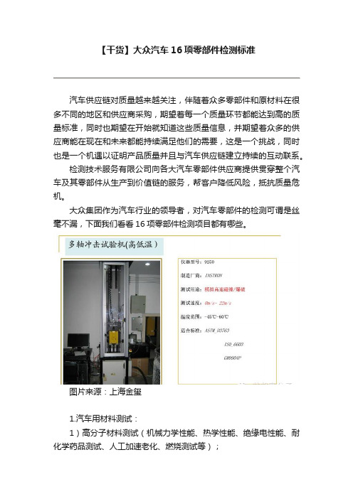
图片来源:上海金玺1.汽车用材料测试:1)高分子材料测试(机械力学性能、热学性能、绝缘电性能、耐化学药品测试、人工加速老化、燃烧测试等);2)反光测试测试(尺寸、颜色、反光性能、耐着力、冲击性能、冲击强度、抗磨性能、色牢度、盐雾试验、压缩性能、绕曲强度、裂纹等);3)泡沫泡棉材料测试(表观密度、压缩形变、硬度、拉伸性能、吸水率、导热系数、反抗弹力、燃烧性能等);4)橡胶材料测试(密度、硬度、拉伸性能、冲击性能、挠曲性能、门尼粘度、热学性能、燃烧试验、人工加速老化试验、耐化学试剂、耐油试验等)。
2.汽车外饰件测试:1)适用产品:汽车前后塑料(金属)保险杠、金属&非金属翼子板、后视镜壳、发动机罩、外装饰件、防撞条等。
2)测试项目:机械力学性能、刚强度、变形量测试、表层厚度测试、附着力测试、抗腐蚀测试、抗磨耗测试、高低温环境测试/紫外线老化测试、紫外/氙弧光老化、高低温环境力学试验、环境机械性能测试、沙尘/淋雨/飞石测试、金相测试、无损探伤、综合性能测试/疲劳耐久测试等。
3.汽车内饰件测试:1)适用产品:方向盘、汽车门内饰件总成、玻璃升降开关、汽车顶棚、遮阳板、车内扶手、立柱饰板、行李箱、各种开关、汽车座椅、汽车地毯等。
2)测试项目:材料重金属成分分析、挥发性有机化合物分析、车内其他受限制成分分析、内饰件材料阻燃成分分析、燃烧性能测试、燃烧烟雾尘粒测试、高低温/湿热测试、高低温冲击测试、温度/湿度/盐度多循环耐腐蚀测试、人工加速紫外光/氙弧光/自然光老化测试、各种环境下的机械冲击、机械拉压、变形量等力学测试、粉尘环境测试、霉斑环境测试、部件的装配、皮革/纺织品性能测试、雾化测试等。
大众点焊标准
分类号:04815 2004年12月德国大众汽车公司镀层/无镀层板件电阻点焊之设计、计算与工艺质量保证VW011 05-1 Konzern标准关键词焊接、点焊、电阻点焊、焊点、板件、钢板、薄钢板本标准英文版翻译准确,如果出现前后不一致,则以德文版为准。
使用前请检查本标准的最新版本。
机密文件,注意保密。
版权所有;未事先得到德国大众集团标准部的书面同意,不得传输或复制本文件中的任何部分。
签约方只能够从主管部门获取本标准。
目次1.范围…………………………………………………………………………2.定义………………………………………………………………………….2.1.点焊………………………………………………………………………… 2.2.热影响区…………………………………………………………………… 2.3.未受影响的母材……………………………………………………………2.4.焊接设计……………………………………………………………………3. 焊接要求…………………………………………………………………… 3.1. 母材(可焊性)……………………………………………………………… 3.2. 焊接设计(焊接性)…………………………………………………………3.3. 生产(焊接能力)……………………………………………………………4. 点焊基础…………………………………………………………………… 4.1最小剪切力F min…………………………………………………………… 4.2. 横向拉力F K…………………………………………………………………4.3. 剥离力F Schäl…………………………………………………………………4.4. 扭力M t………………………………………………………………………4.5. 静态和动态应力负载…………………………………………………………4.6. 工艺质量保证…………………………………………………………………5. 图纸……………………………………………………………………………..6. 引用标准………………………………………………………………………如需计算例证,请参阅本标准附件1。
VW 01106-1 (04.07)
插图 1 – 熔焊接合 附注:焊缝和熔焊线可以是同一的。
2.2.1.1 焊缝
在焊接接头处,于焊接接合范围内结合工件或者多只工件。其焊缝由基体材料和/或焊接添加剂材 料组成。
2.2.1.2 熔焊线 在焊接情况下,已熔化的基体-和/或添加剂材料与未熔化的基体材料之间的界限。
材料编号
1.0972 1.0976 1.0980 1.0982 1.0984 1.0986 1.8969 1.8976 1.8974
页次 7 VW 011 06-1: 2004-07
i) 由磷化钢制成的,具有较高冷成形屈服极限的冷轧带钢和钢板:
SEW 094 ZStE220P ZStE260P ZStE300P DIN EN 10292 H220PD+Z, +ZF H260PD+Z, +ZF H300PD+Z, +ZF
对保护气体焊接的进一步要求包含:
VW 011 06-2
对钢板焊接接合的再加工
VW 011 06-3
铝板的焊接接合
VW 011 42
关于铝板的焊接接合方面的再加工
在电弧焊制作钢板焊接接合的情况下,在结构目标含义上,足够安全性的前提下,实现最大可能 的造形强度。由此,对每种焊接接合,必须计及“正确焊接”,也就是说,在研发结构设计的情况 下,必须按照 DVS 0929,考虑焊接装置的尺寸和焊缝的可接近性。
用于: 对接焊缝与贴角焊缝,搭接焊缝,塞孔焊缝和特种焊缝形状
由…制成 光亮非镀层和镀层钢板以及由高合金钢和优质钢制成的钢板;示例参见章节 4.1;
附带: 按照 DIN EN ISO 5817 的评价组别的特征值,也可参见 DVS-标记卡 0705。
大众汽车标准_VW 01141-2 参考译文

Vertragspartner erhalten die Norm nur über die zuständige Beschaffungsabteilung.Confidential. All rights reserved. No part of this document may be transmitted or reproduced without the prior written permission of a Standards Department of the Volkswagen Group.Parties to a contract can only obtain this standard via the responsible procurement department.1999.03 ~ VOLKSWAGEN AG4、评定标准表一:不规则特性,外部测试(可视测试)Page 3VW 010 89: 2003-022.3 Graphical representationThe spacer areas are always shown on the single part drawing, not on the assembly drawing.The spacers may partially protrude from the flange area (e.g. as the result of subsequent trimming of the flange).The position of the spacers is always oriented to the material vector (see Figure 2).Supplementary to the graphical representation of laser welded joints (according to VW 011 41-1 or DIN EN 22 553), the position of the spacers is represented as in figure 1. A dash-dot line identifies the spacer area. Legend: Shape A = Information on spacer direction and sheets involved Figure1 – Graphicalrepresentation (on a flange,for example)The shape letter describesthe embossing direction of thespacers relative to thedirection of the materialvector.! Shape A Spacer isembossed inthe direction ofthe materialvector, 2-sheetjoint, contact onone side; entryin the data seton layer 190! Shape B Spacer is embossed in the opposite direction to the material vector, 2-sheet joint, contact on one side; entry in the data set on layer 191! Shape C Spacer is embossed on alternate sides in the middle sheet (exception: see section 2.2, first paragraph), 3-sheet joint, contact on both sides; entry in the data set on layer 192.Shape A Shape B Shape C!Figure 2 - Spacer shapes (draft not to scale)The distance between the spacers on the indicated flange area shall be geometrically even; the distances to the edge of the contact area (first/last spacer) shall be adhered to.Page 4VW 010 89: 2003-022.4 Specifications in the 3D CAD model (data set)The representation in the 3D model initially corresponds to the representation in the drawing. The spacer areas are represented using a dash-dot line, but not as protrusions.The area limits shall be created on discrete layers in the 3D model (for the CAD system CATIA on layer 190 for shape A, layer 191 for shape B and layer 192 for shape C, see VW 010 59-3, appendix1).2.5 Definition of the spacer positionThe exact spacer position is defined in the SET1).The tool manufacturer (represented by the planning department for single parts) enters the exact position of the spacers into the data set. Each spacer is represented by a 10 mm line on layer 193 in the spacer direction.The data set is provided to the ASSY planning department for review. Any additions such as the insertion of spacers in the ASSY are made on layer 194 (body construction scope).In the case of supply parts, the spacers are defined between the supplier and design department based on specifications from Manufacturing Planning.2.6 Effects on the body-in-white assemblyThe addition of spacers can cause the vehicle dimensions to change by the total of the spacer height values. The resulting deviations in the nominal dimensions of the vehicle shall be compensated in the assembly by agreement.2.7 OtherDegassing must always be ensured for laser welded joints. This can be done using other measures, not described in this standard, agreed with the body construction engineering department without changing the spacer specifications in the drawing.3 Referenced standardsPV 6719VW 010 55VW 010 59-3, app. 1 VW 011 41-1 DIN EN 22 553 39D 962 Laser Welding on Coated Steels; Plain Butt Weld at the Lap Joint; Multiple Sheet WeldingReference Point System (RPS); DrawingsRequirements for CAD/CAM Data, Process-Specific Layer Assignment Laser Welding of Sheet Steel; Design, Execution, Quality Assurance Welding and Brazing Seams; Symbolic Representation in Drawings Operating Equipment Standard: Stamp for Spacers for Laser Welding1) SET: Simultaneous Engineering Team (see PEP manual)。
VW011 06-1大众汽车气体保护焊标准 (中文版)
2004年7月气体保护焊钢板焊接结构、规格、质量保证VW011 06-1 标准中心 704 81 7后续2至24页翻译日期校对日期打字日期关键词:焊接,气体保护焊,钢制品,电弧焊接法,磁铁焊接,钨极惰性气体焊,钢板,钢皮焊接,板材目录页1适应范围 (2)2 缩写词和定义 (2)2.1缩写词 (2)2.2 定义 (3)3 汽车保护焊工艺说明 (4)3.1钨-惰性气体焊接(WIG) (4)3.2 金属-气体保护焊(MIG/MAG) (4)4 技术要求概述 (5)4.1材料 (5)4.2 结构设计 (8)4.3 焊缝尺寸 (10)5 焊缝的技术要求和质量保证 (12)5.1焊接质量 (12)5.2 焊接熔深 (12)5.3 焊缝形态 (13)5.4 特殊焊缝形态 (18)5.5 不均匀性的评估 (23)6 图纸数据 (23)7 相关参考文献 (23)更改同VW 011 06-1:2003-05比较,做了如下更改:—参见标准有所更改—标准从编辑角度作了一些修改— 5.1条有所简化— 5.4条特殊焊缝形状(多路顶焊道,焊接角接头)有所扩充— 5.4.1条技术要求有所变动以前版本1997-01;2003-05前言后面将要涉及的基本原理,其基础就是局部或全部机械化设备运用的经验和所完成的一系列试验,以及公认的工艺原则,例如:DIN标准、DVS(德国焊协)-标记卡等提供的工艺原则.第 2 页 VW 011 06-1:2004-07 1适用范围该标准适用于钢板电弧焊的结构设计、规格和质量保证,这种焊接法在大多数情况下都会使焊件动态地产生应变。
按照DIN EN ISO 4063的规定,本标准包括了下面的方法:特征数方法缩写词131金属惰性气体焊MIG135 金属活性气焊MAG141钨惰性气体焊WIG用于:对接焊缝和填充焊缝、搭接焊缝、电铆焊接和特殊焊缝。
焊材:光洁的、无涂[镀]层和有涂[镀]层的钢板,高合金钢、优质钢等;样品见第4.1条;工件厚度为0.5 mm至6 mm。
大众汽车标准_VW 01106-1_EN_2004-07-01

Gas-Shielded Arc WeldingThe English translation is believed to be accurate. In case of discrepancies the German version shall govern.Sheet Steel Joints Design, Type, Quality AssuranceVW 011 06-1Konzernnorm Descriptors: welding, gas-shielded arc welding, steel, MIG welding, MAG welding, TIG welding, sheet steel, sheet steel joint, sheet metal ContentsPage1 2 2.1 2.2 3 3.1 3.2 4 4.1 4.2 4.3 5 5.1 5.2 5.3 5.4 5.5 6 7Scope .................................................................................................................................. 2 Abbreviations and definitions .............................................................................................. 2 Abbreviations ...................................................................................................................... 2 Definitions ........................................................................................................................... 3 Gas-shielded arc welding procedure................................................................................... 4 Tungsten inert-gas welding (TIG)........................................................................................ 4 Gas-shielded metal arc welding (MIG/MAG)....................................................................... 4 General requirements ......................................................................................................... 5 Materials.............................................................................................................................. 5 Design ................................................................................................................................. 8 Weld dimensions............................................................................................................... 10 Requirements for welds and quality assurance of welds .................................................. 12 Weld quality....................................................................................................................... 12 Penetration depths ............................................................................................................ 12 Weld types ........................................................................................................................ 13 Special weld types ............................................................................................................ 18 Evaluation of imperfections ............................................................................................... 23 Drawing entries ................................................................................................................. 23 Referenced standards....................................................................................................... 24Changes The following changes have been made as compared to VW 011 06-1, 2003-05: Referenced standards updated Standard edited Section 5.1 shortened Section 5.4 extended by special weld types (multiple front weld; corner joint) Section 5.4.1: requirements revised Previous issues 1997-01; 2003-05Preface The following basic regulations are based on experience gained with partially and fully mechanized equipment and implemented tests and also on accepted engineering standards such as DIN standards and DVS specifications.Form FE 41 - 01.03Page 1 of 25Fachverantwortung/Responsibility K-QS-32 Herr Dr. Witt Tel.: 7 36 23 Normung/Standards (EZTD, 1733) Fischer Tel.: +49-5361-9-2 79 95 Sobanski© VOLKSWAGEN AGConfidential. All rights reserved. No part of this document may be transmitted or reproduced without the prior written permission of a Standards Department of the Volkswagen Group. Parties to a contract can only obtain this standard via the responsible procurement department.Check standard for current issue prior to usage.Klass.-Nr./Class. No. 04 81 7July 2004Page 2 VW 011 06-1: 2004-07 1 ScopeThis standard applies to the design, layout and quality assurance of arc-welded sheet steel joints which are predominantly subject to dynamic loads. It comprises the following procedures according to DIN EN ISO 4063: Reference no. 131 135 141 for: of: Method Metal inert-gas welding Metal active-gas welding Tungsten inert-gas welding Code MIG MAG TIGbutt and fillet welds, lap welds, plug welds and special weld types bright uncoated and coated sheet steel as well as of both high-alloyed steels and premium steels; for examples see Section 4.1; Workpiece thickness 0.5 mm to 6 mm test characteristics of quality level B (high requirement) according to DIN EN ISO 5817, see also DVS specification 0705.with:All fusion-welded joints to which this scope is not applicable require the clarification of the responsible engineering departments. Special measures made necessary because of the component, e.g. change to the quality level for specific imperfections, are permissible and shall be entered in the drawing. 2 2.1 a f1,2 fL fSt Fi h l L s s1,2 sN t1 t2 HAZ Σt ∅ Abbreviations and definitions Abbreviations Calculated throat thickness Penetrations on sheets 1 and 2 Penetration length Penetration at the face surface Joining plane Gap size Throat length Length Throat thickness Throat thickness with respect to sheets 1 and 2 smallest common throat thickness Thickness of sheet 1 Thickness of sheet 2 Heat-affected zone Sum total of sheet thicknesses Diameter mm mm mm mm or % (of face surface) mm mm mm mm mm mm mm mm mm mmPage 3 VW 011 06-1: 2004-072.2DefinitionsFüThe following definitions are valid for the application of this standard: 2.2.1 Weld jointJoint created by fusion welding. It comprises the weld, fusion line, heat-affected zone and unaffected base material (Figure 1).1 2Legend: 1 = weld 2 = heat-affected zone 3 = fusion line, fusion zone344 = unaffected base material Figure 1 – Fusion weld jointNOTE Weld and fusion line may be identical. 2.2.1.1 Weld The area where the workpiece(s) is/are joined at the weld joint. The weld comprises the base material and/or the filler metal. 2.2.1.2 Fusion line Borderline between the base metal and/or filler material melted during welding and the metal that remains solid. 2.2.1.3 Weld metal Material that solidified after welding, comprising either the base material or filler metal and base material. Some elements in the weld metal can come from casings and/or accessory materials (DIN ISO 857-1). 2.2.1.4 Heat-affected zone HAZ Area of the base material that remained solid, but, due to the energy applied during welding, experienced microstructural changes related to temperature.Page 4 VW 011 06-1: 2004-072.2.1.5 Unaffected base material Area of the base material that experienced no evident microstructural changes as a result of the energy applied during welding. 2.2.2 Same types of materialMaterials which do not differ significantly in terms of their chemical composition and their suitability for welding (DIN 8528-1). 2.2.3 Different types of materialMaterials which differ significantly in terms of their chemical composition and their suitability for welding. 3 Gas-shielded arc welding procedureGas-shielded arc welding is a form of fusion welding. An electrical arc is used as the heat source. It burns between the electrode and the workpiece. In this process, the arc and the weld pool are protected from the atmosphere by a shield of protective gas. The classification into the following procedures depends on the electrode type: 3.1 Tungsten inert-gas welding (TIG)In this procedure, an arc is ignited between a non-consumable tungsten electrode and the workpiece. Argon, helium, mixtures of both and sometimes added active gases, are used to form the protective atmosphere. The filler metal is (as in the case of gas welding) fed from the side. 3.2 Gas-shielded metal arc welding (MIG/MAG)In this procedure, an arc is ignited between the melting end of the wire electrode (filler metal) and the workpiece. The welding current flows via sliding contacts in the electric current guide of the gun to the wire electrode. When inert gases (low-activity gases, e.g. noble gases such as argon, helium or mixtures of both) are used as protective atmosphere, this is called metal inert-gas welding (MIG). When active gases are used (e.g. CO2, or mixtures containing CO2, or, in some cases, mixtures of CO2 and oxygen), this is called metal active-gas welding (MAG). This procedure is used to weld unalloyed and low-alloy steels.Page 5 VW 011 06-1: 2004-074General requirementsWelds that are subject to mandatory documentation shall be evaluated according to the relevant type-specific and/or component-specific test specifications (PV). Deviations with respect to the specified weld geometries and weld layouts shall be detailed in the drawing and verified by testing. They shall be described in test specifications (PV). Further requirements with respect to gas-shielded arc welding are contained in the following documents: VW 011 06-2 VW 011 06-3 VW 011 42 Shielded Arc Welding - Rework on Sheet Metal Connections Gas-Shielded Arc Welding – Part 3: Al Welded Joints Welded Seam Repairs on Aluminum Structures – Product Evaluation and Notes on ProcedureWhen creating arc-welded sheet steel joints, the greatest possible design strength in accordance with the design goal must be realized while also ensuring sufficient reliability and a favorable cost/quality ratio. For this purpose, every weld joint must be suitable for welding, i.e. the dimensions of the welding equipment and the accessibility of the weld according to DVS 0929 must be taken into consideration for design. Weldability for service of a sheet steel joint is given if the component, on the basis of its design (Section 4.2) and with the material used (Section 4.1), remains functional (Section 4.3) under the intended operating stresses (Figure 2).Material Welding suitabilityWeldability of the partWelding capability ManufacturingWeldability for service DesignFigure 2 – Representation of weldability according to DIN 8528-1 4.1 MaterialsThe following list is not complete. The following products and materials have good welding properties: a) Cold-rolled flat products made from soft steels for cold forming: DIN 1623-1 (02.83)1) DIN EN 10130 Material no. St 12 DC01 1.0330 St 13 DC03 1.0347 St 14 DC04 1.0338 1) DIN 1623-1 was replaced in October 1991 by DIN EN 10130.Page 6 VW 011 06-1: 2004-07b) c) d)Cold-rolled strips DC01 to DC04 with the surface finishes BK, RP, RPG according to DIN EN 10139. Hot-rolled strips with ≤ 0.20% C content, e.g. according to TL 1111. Hot-rolled products of structural carbon steels DIN 17100 (01.80)2) DIN EN 10025 Material no. St 37-2 -1.0037 St 37-2 R St37-2 S 235 JR 1.0114 St 37-3 S 235 JO 1.0116 St 52-3 S 355 J2G3 1.0570 Conditionally weldable: St 50-2 E295 1.0050 2) DIN 17100 was replaced in March 1994 by DIN EN 10025.The following products and materials are also weldable:e) f)g)Cold-rolled strip and sheet with higher yield point for cold working made from micro-alloyed steels (SEW 093 of March 1987) Isotropic micro-alloyed cold-rolled strip (according to VW 500 17) is a further development of the traditional micro-alloyed cold-rolled strip ZStE260 to ZStE420 (formerly SEW 093). NOTE VW 500 17 defines the material requirements of isotropic micro-alloyed steels, placing particular emphasis on the mechanical properties. Cold-rolled flat products with high yield point for cold working made from micro-alloyed steels: DIN EN 10268 Material no. H240LA 1.0480 H280LA 1.0489 H320LA 1.0548 H360LA 1.0550 H400LA 1.0556 DIN EN 10292 Material No. H260LAD+Z, +ZF 1.0929 H300LAD+Z, +ZF 1.0932 H340LAD+Z, +ZF 1.0933 H380LAD+Z, +ZF 1.0934 H420LAD+Z, +ZF 1.0935 Hot-rolled flat products made from steels with a high yield point for cold working: DIN EN 10149-2 Material no. S315MC 1.0972 S355MC 1.0976 S420MC 1.0980 S460MC 1.0982 S500MC 1.0984 S550MC 1.0986 S600MC 1.8969 S650MC 1.8976 S700MC 1.8974h)Page 7 VW 011 06-1: 2004-07i)Cold-rolled strip and sheet with higher yield point for cold working made from phosphorus-alloy steels SEW 094 Material no. ZStE220P 1.0397 ZStE260P 1.0417 ZStE300P 1.0448 DIN EN 10 292 Material no. H220PD+Z, +ZF 1.0358 H260PD+Z, +ZF 1.0431 H300PD+Z, +ZF 1.0443 Strip and sheet from stainless steels (DIN EN 10088-2): e.g. austenitic steels X5CrNi18-10 1.4301 or ferritic steels X2CrTi12 1.4512j)Page 8 VW 011 06-1: 2004-074.2DesignFüThe following specifications and the notes on design from the DVS 0929 Specification are used as the basis for the production-friendly design of arc-welded sheet-steel joints. 4.2.1 Joint typesThe weld joint is the area in which the parts are joined by welding. The respective type of joint is determined by the arrangement of the parts with respect to each other (extension, reinforcement, branching), see Table 1. Table 1 – Joint types (DIN EN 12345) Position of parts Description The parts lie in the same plane and touch against each other end to end The parts lie on top of one another in parallel, e.g. in explosive cladding The parts lie in parallel on top of one another and overlap. The parts meet at right angles (Tshaped) and lie on top of one another Two parts lying in the same plane meet on a third part that lies between them at right angles (forming a double T shape) One part meets the other at an angle. The edges of two parts meet at an angle of more than 30° (corner)No. 1 2 3Type of joint Butt joint Edge joint Lap joint4T-joint5Double T-joint6Bevel joint7Corner joint8Front jointThe edges of two parts meet at an angle of 0° to 30°9Multiple jointThree or more parts meet at any angle Two parts, e.g. wires, lie on top of one another in a cross shape10Cross jointPage 9 VW 011 06-1: 2004-074.2.2Weld typesThe weld type is determined by the following: Type of weld joint Type and scope of preparation, e.g. gap optimization (see DIN EN ISO 5817 and DIN EN ISO 9692-1) Material Welding method. 4.2.2.1 Fillet weld The parts lie in two planes with respect to one another, form a fillet joint and are joined by welding. It is possible to differentiate between a fillet weld (Figures 3 and 5) and a double fillet weld (Figure 4) with and without edge preparationFigure 3 - Fillet weld on T-jointFigure 4 – Double fillet weld on T-jointFigure 5 - Fillet weld on bevel joint without edge preparation4.2.2.2 Square butt weld on butt joint, flanged weld The parts lie in one plane, form a gap and are joined by welding, see Figures 6 and 7.Figure 6 - Square butt weld 4.2.2.3 Lap weldFigure 7 – Flanged weldThe parts lie in parallel on top of one another. The face surface of the top sheet and the bottom sheet form a fillet. Both parts are joined by welding. This is termed lap weld (see Figure 8). Variant 1 Variant 2Figure 8 – Lap weldPage 10 VW 011 06-1: 2004-074.2.2.4 Front weld See Figure 9.Figure 9 – Front weld 4.2.2.5 Plug weld See Figure 10.Figure 10 – Plug weld 4.3 4.3.1 Weld dimensions Throat thicknessThe calculated throat thickness a is required for the calculation of the forces acting on a weld joint. For example, the following applies to the design of a fillet weld: a ≤ 0.7 tmin. In production, the actually measured throat thickness s must always be greater than or the same as the calculated throat thickness a. If the throat thickness s (Figure 11) cannot be determined directly, the smallest common throat thickness sN (Figure 12) can be used for an alternative criterion. The smallest common throat thickness sN is the shortest distance between the contact surfaces of component edge and weld metal and the surface of the weld (see also Figures 13 and 14).sN saaFigure 11 - Fillet weldFigure 12 - Fillet weld with deep penetrationPage 11 VW 011 06-1: 2004-07sNsNFigure 13 – Concave weldFigure 14 – Convex weldThe shortest (common) distance between both components of the weld joint shall be measured in order to determine the shortest common throat thickness sN. Excess weld metal must not be considered for convex welds (see Figure 14). 4.3.2 Weld lengthThe calculated weld length l is the weld length defined for the specific design by the designer. Both the starting and end areas (end crater) are used to determine the weld length. In order to improve the dynamic load capacity, the weld length can exceed the component length (Figure 15).l1 = Calculated weld length e.g. component length l2 = Weld seam length Figure 15 – Magnified weld length Proof of sufficient strength is provided by the component-specific strength tests.Page 12 VW 011 06-1: 2004-075Requirements for welds and quality assurance of weldsIn general, the welding quality requirements according to DIN EN 729-1 shall be taken into consideration together with the comprehensive quality requirements set out in DIN EN 729-2. The design of a weld shall be described clearly by indicating the weld’s length, thickness and quality. These requirements are part of the drawing specifications (also see Section 6). Unless other specifications are noted in the drawing, the requirements of Sections 5.1 to 5.5 shall apply. 5.1 Weld qualityIf there is no component-specific test specification, quality level B, high, specified in DIN EN ISO 5817, shall apply. The imperfections specified there are represented for square butt welds and fillet welds on a T-joint. The limit values for imperfections apply to other weld types, too (e.g., flanged weld, fillet weld on lap joint). Unequal weld leg lengths as an imperfection according to DIN EN ISO 5817 must not be evaluated for the fillet weld in joints of sheet metal in the body-in-white and in exhaust systems. 5.2 Penetration depthsThe weld joint is sufficient once a continuous crystalline joint with a measurable penetration depth of f ≥ 0.2 mm is created between the sheets involved. For certain weld types – e.g. fillet weld on lap joint or flanged weld – the penetrations f cannot always be determined if 100% of the face surfaces is included in the weld. Permissible penetration depths f < 0.2 mm shall be indicated in the drawing or specified in a component-specific test specification. The weld quality and/or strength must be verified by means of a dynamic strength test and a microscopic examination. NOTE: Due to the smaller “welding window” the test intervals for f < 0.2 mm (e.g. using microsections) shall be conducted at shorter time intervals or on smaller batch sizes. The processes shall be coordinated with all the departments involved (Design, Quality Assurance, Production).Page 13 VW 011 06-1: 2004-075.3 5.3.1Weld types Square butt weld on butt jointt1sFigure 16 - Square butt weld on butt joint s = throat thickness fSt = penetration The face surfaces (fSt ) shall be 100% melted. Design as flanged weld: s ≥ tmin. (see Figure 16) fSt ≥ 100 %SNt1Figure 17 – Flanged weld sN = smallest common throat thickness The face surfaces (fSt ) shall be 100% melted. sN ≥ tmin. (see Figure 17)t2t2Page 14 VW 011 06-1: 2004-075.3.2Front weldSNf1 SN fL2sNf2t1t2 t1a) b) Figure 18 – Front weld sN fL2. f1,2 tmin. t1 0.2 mmt2t1c)t2sN = smallest common throat thickness fL2 = penetration length f1,2 = penetration 5.3.3 Fillet weld on lap joints1 sN N af2t1hs2Figure 19 - Lap weld s1,2 sN a f2 h = throat thickness = smallest common throat thickness = calculated throat thickness = side wall penetration on the component t2: = gap size s1,2 0.7 tmin. sN f2 s1,2 and sN 0.7 tmin. a ≤ 0.7 tmin. (design recommendation) 0.2mm (see Figure 19)NOTE: If the throat thicknesses s1,2 cannot be determined directly, the smallest common throat thickness sN may be chosen as an alternative criterion.t2Page 15 VW 011 06-1: 2004-075.3.4Fillet weld with deep penetrationt1 f1 s1 sNt2aTheoretical root pointFigure 20 - Fillet weld with deep penetration s1,2 sN a f1,2 = throat thickness (with deep penetration) = smallest common throat thickness = calculated throat thickness = side wall penetration on component t1,2 s1,2 0.7 tmin. sN s1,2 and sN 0,7 tmin. a ≤ 0.7 tmin. f1,2 0.2 mm (see Figure 20)NOTE: If the throat thicknesses s1,2 cannot be determined on the microsection directly, the smallest common throat thickness sN may be chosen as an alternative criterion. 5.3.5 Fillet weld on bevel jointt1sN≤ 30°Figure 21 - Fillet weld on bevel joint sN = throat thickness f2 = penetration sN f2 tmin. 0.2 mm (see Figure 21)The face surface of the upper sheet must be 100 % melted.f2t2f2 s2Page 16 VW 011 06-1: 2004-075.3.6Multiple jointf1f2lt1t3Figure 22 – Three-sheet-T-joint f1,2,3 = penetration fSt1,2 = face surface penetration of t1,2 fSt3 = face surface penetration of t3 5.3.7 Corner joint f1,2,3 > 0.2 mm fSt1,2 ≥ insertion depth l fSt3 = 100% meltedsNt1t2Figure 23 – Corner joint The face surfaces of both sheets must be 100 % melted. Smallest common throat thickness sN ≥ tmin.t2Page 17 VW 011 06-1: 2004-075.3.8Plug weldFor plug weld see Figure 24. The values in Table 2 serve as reference values for the ratio of the sheet thickness to the hole diameter. Table 2 – Hole diameter and sheet thickness Sheet thickness used t (mm) up to 1.0 > 1.00 to 1.25 > 1.25 to 1.50 > 1.50 to 2.00 > 2.0 to 3.00 > 3.00 to 3.50 Hole diameter ∅ or L (mm) ≥6 ≥7 ≥8 ≥9 ≥ 10 ≥ 14 Optionally, long holes for narrow flanges W x L (mm) 6 x 10 6 x 12 8 x 12 -When there are gaps between the sheets, the length of the penetration fL must be equivalent to the length L or to the diameter of the hole, or exceed it. ∅ or L x Bt1 t2 fLf2fSt1,2 = face surface penetration of t1,2 fL = penetration length, width and/or diameter f2 = penetration depthfSt1,2 = 100 % melted fL ≥ ∅ or L or W f2 ≥ 0.2 mm Figure 24 – Plug weldThe face surfaces of the hole must be 100 % melted.Page 18 VW 011 06-1: 2004-075.4Special weld typesAdequate evaluation criteria shall be used to evaluate any special weld types that are not listed here. 5.4.1 Fillet weld on multiple lap jointS1t1 t2 t3 f3S2Figure 25 - Three-sheet lap weld The cross-sections of the upper sheets t1 and t2 must be 100 % melted and the throat thickness a of t1 and t2 must be met. If no specifications are made in the drawing, the following applies as reference value: a = 0.7 tmin2,3 The penetration depth f3 in sheet t3 shall be minimum 0.2 mm.Page 19 VW 011 06-1: 2004-075.4.2Multiple front weld sN2 sN1 sN3 F1 F2 Fi = joining plane i F3 *1) If it is clear that one sheet arrangement in a multiple-sheet arrangement is to be considered as a single sheet, then this sheet shall not be included in the overall evaluation when determining the throat thickness sN. t1 t2 t3 t4*1)Figure 26 – Four-sheet front weld In the case of multiple-sheet joints, the smallest common throat thickness sN of the relevant joining planes is used to determine the throat thickness s, as is the case for a multiple lap joint. Here the following applies: In the relevant joining plane (in Figure 26 - four-fold front weld with the joining planes F1, F2 and F3) the throat thickness sN must be ≥ Σ of the sheet thicknesses on the right and = Σ of the sheet thicknesses on the left of the joining plane. The following applies to Figure 26 as an example: sN1 ≥ t 1 sN2 ≥ ? t(3+4) sN3 ≥ ? t4 fSt = face surfaces t1 t4 < (t2 + t3 + t4 ) < (t1 + t2 + t3 ) t3 + t4 < (t1 + t2 ) fSt 1,2,3,4 = 100% meltedPage 20 VW 011 06-1: 2004-07sN4sN3sN 2 s N1t1 t t34t2Figure 27 – Multiple front weld For multiple front welds in exhaust systems (e.g., sheet layers on the exhaust pipe, Figure 27) the factor 0.7 applies in the determination of the smallest common throat thickness sN: sN1 ≥ 0.7 t1 sN2 ≥ 0.7 (t1 + t2) sN3 ≥ 0.7 (t1 + t2 + t3) sN4 ≥ 0.7 tpipe or or sN2 ≥ 0.7 (t3 + t4) sN3 ≥ 0.7 t4Page 21 VW 011 06-1: 2004-075.4.3Fillet welds on components with round cross sectionsf1 sNtaFigure 28 - Fillet weldt f1 = = t2 f2Figure 29 - Fillet weld with deep penetrationsFigure 30 – Concave fillet weld For Figures 28 and 30 determine the throat thickness s approximately: On workpieces with different geometrical shapes, the shortest distance of the median line between the two workpieces shall be selected as the dimension s. s = throat thickness s ≥ 0.7 tminFor fillet welds on components with a round cross section it is recommended to determine the smallest common throat thickness sN as shown in Figure 29. sN = smallest common throat thickness sN ≥ a. NOTE: In the event of imperfections, e.g. undercuts, DIN EN ISO 5817 shall apply.f2Page 22 VW 011 06-1: 2004-075.4.4Square butt weld on flanged jointf1 f2 t1 sN t2Figure 31 - Fillet weld on specially shaped workpieces sN = smallest common throat thickness f1,2 = penetration depth sN ≥ tmin. (see Figure 31) f1,2 ≥ 0.2 mmPage 23 VW 011 06-1: 2004-075.5 5.5.1Evaluation of imperfections Weld spatterWeld spatter must be avoided as far as possible. Any globules or welding residues that remain stuck to the parts and which could lead to an impairment of function are not permitted. Spatter-free areas shall be defined in the drawing or in a test specification. 5.5.2 General imperfectionsImperfections such as cracks, pores, lack of fusion, gap sizes shall be evaluated, unless otherwise indicated in the drawing, according to DIN EN ISO 5817, quality level B “high”. Unequal weld leg lengths shall not be evaluated for fillet welds on lap joint. For exhaust systems the gap size must not exceed 1.0 mm. 6 Drawing entriesThe graphical representation (for example see Figure 32), dimensioning and symbols for the welding procedures named in Section 1 shall be carried out according to DIN EN 22553.s8a6n x l (e)131/ VW01106-1/h Legend: s8 = actual throat penetration) 8 mm thickness (with deepva6 = design throat thickness (without deep penetration) 6 mm n = number of welds l = minimum weld length; tolerance +5 mm, unless otherwise indicated e = distance between the welds v = initial dimensionExplanation: Weld produced by means of metal inert-gas welding (code number 131 according to DIN EN ISO 4063); evaluation according to VW 011 06-1; horizontal position h according to DIN EN ISO 6947. Figure 32 - Example of application for interrupted fillet weld with initial dimension; symbolic representationPage 24 VW 011 06-1: 2004-077Referenced standards1 Steel Flat Products; Cold Rolled Sheet and Strip; Technical Delivery Conditions; Mild Unalloyed Steels for Cold Forming Weldability; Metallic Materials, Definitions Steels for General Structural Purposes; Quality Standard Quality Requirements for Welding - Fusion Welding of Metallic Materials – Part 1: Guidelines for Selection and Use Quality Requirements for Welding - Fusion Welding of Metallic Materials – Part 2: Comprehensive Quality Requirements Hot Rolled Products of Non-Alloy Structural Steels; Technical Delivery Conditions Stainless Steels - Part 2: Technical Delivery Conditions for Sheet/Plate and Strip of Corrosion-Resisting Steels for General and Construction Purposes Cold Rolled Low Carbon Steel Flat Products for Cold Forming – Technical Delivery Conditions Cold Rolled Uncoated Mild Steel Narrow Steel Strip for Cold Forming Technical Delivery Conditions Hot Rolled Flat Products Made of High Yield Strength Steels for Cold Forming – Part 1: General Delivery Conditions Hot Rolled Flat Products Made of High Yield Strength Steels for Cold Forming – Part 2: Delivery Conditions for Thermomechanically Rolled Steels Cold-Rolled Flat Products Made of High Yield Strength Micro-Alloyed Steels for Cold Forming - General Delivery Conditions Continuously Hot-Dip Coated Strip and Sheet of Steels with Higher Yield Strength for Cold Forming – Technical Delivery Conditions Welding - Multilingual Terms for Welded Joints with Illustrations Welded, Brazed and Soldered Joints - Symbolic Representation on Drawings Welding – Fusion-Welded Joints in Steel, Nickel, Titanium and Their Alloys (Beam Welding Excluded) – Quality Levels for Imperfections Welding and Allied Processes - Nomenclature of Processes and Reference Numbers Welds - Working Positions - Definitions of Angles of Slope and Rotation Welding and Allied Processes – Recommendations for Joint Preparation Part 1: Manual Metal-Arc Welding, Gas-shielded Metal-Arc Welding, Gas Welding, TIG Welding and Beam Welding of Steels Welding and Allied Processes – Vocabulary - Part 1: Metal Welding Processes Recommendations for Selection of Acceptance Levels according to DIN EN 25 817; Butt Welds and Fillet Welds on Steel Notes on Design for MIG/MAG Welding using Industrial Robots Cold-Rolled Strip and Sheet of Micro-Alloyed Steels with Higher Yield Point for Cold Forming – Technical Supply SpecificationsThe last publication date of withdrawn standards is provided in parentheses. DIN 1623-1 (02.83) DIN 8528-1 DIN 17100 (01.80) DIN EN 729-1 DIN EN 729-2 DIN EN 10025 DIN EN 10088-2 DIN EN 10130 DIN EN 10139 DIN EN 10149-1 DIN EN 10149-2 DIN EN 10268 DIN EN 10292 DIN EN 12345 DIN EN 22553 DIN EN ISO 5817 DIN EN ISO 4063 DIN EN ISO 6947 DIN EN ISO 9692-1 DIN ISO 857-1 DVS 0705 DVS 0929 SEW 093 (03.87)1In this section terminological inconsistencies may occur as the original titles are used.。
VW_01106-1 气体保护焊

1.0330
St 13
DC03
1.0347
St 14
DC04
1.0338
1)DIN 1623-1 在 1991 年 10 月,由 DIN EN 10130 替代。
第6页 VW 011 06-1:2004-07
b) 冷轧带钢 DC01 至 DC04 具有 DIN EN 10139 所规定的表面特性 BK、RP、RPG。 c) 热轧带钢具有≤0.20%的 C-含量,例如 TL 1111 中规定的。 此外就是可焊性: d) 非合金结构钢制的热轧产品
各种熔焊方法,如果在本标准范围内未予取消,则需要主管专业部门予以说明。由于对 构件的限制而必须采取特殊措施,例如为了确定不一致性而改变评估小组成员,这种做法 是允许的,但必须记入图纸。
2
缩写词和定义
2.1 缩写词
a
焊缝计算厚度
f1,2
1 或 2 厘米钢板的焊焰穿透
fL
焊焰穿透长度
fSt
端面上焊焰穿透
均质材料,就是其化学成份及其焊接适应性(DIN 8528-1)与母材无重要差异的材料。
2.2.3 异质材料
异质材料,就是其化学成份及其焊接适应性与母材均有重大差异的材料
3
气体保护焊工艺说明
气体保护焊是属于保护焊的一种。电弧是这种焊接的能源,电弧在工件和焊条之间燃烧。 这时候,由同一个“气体保护罩”盖住熔池和焊条,使之与大气隔绝。
DIN 17100(01.80)2)
DIN EN 10025
St37-2
--
St37-2 R St37-2
S 235 JR
St37-3
S 235 JO
St52-3
S 355 J2G3
大众汽车标准_VW_01105-1_电阻点焊
共36页第 1 页关键词:焊接,点焊,电阻点焊,焊接点,板材,钢,钢板前言本标准中概述包括术进步的过程中,将在相应章节中专门说明。
计算例证在本标准的副篇各种不同的简要说明适用12变更 相对于VW 011 05-1:2003-05有如下更改处:-第4.3.1节公差一章增加较小的点焊直径和松动的焊接点内容。
先前版本 1977-05;1993-12;2003-051应用范围 下列基本原则是以少批量到大批量机械化点焊程度和研究结果的经验为基础,以及公开发表的标准和技术规则,例如DVS-规则2902-1,-2,-3。
本标准适用有关静态和动态要求的电阻点焊的钢板结构的形状、计算和实施,在其他的文件中称之为“点焊连接”。
本标准应用范围包括接口点焊连接上的(电阻)点焊(特性因数21按照DIN EN ISO 4063),其在无涂层的板材上的板材厚度比例,板材厚度从0.5~4 mm,以及有关单点和多点焊接的过程保证的质量特征。
在特殊情况下,遇到较大的板材厚度和比例情况请与专业部门进行协调。
按照DIN EN 10 139使用的板材其厚度最多只能够是3.0 mm 。
引进镀锌板材,例如按照DIN EN 10 142或DIN EN 10 292, 和高和高硬度钢的部件要求具备直径较大的电极罩和电极套筒(16 mm 及 20 mm)。
该电极的部件上,当点焊法兰盘发生弯曲时焊核脱离连接片部位。
随着焊核与连接片之间出现的增大的距离现象构件的坚固性和构件强度随之降低。
另外有关(电阻)点焊连接的要求包括:VW 011 05-2(铝材料)VW 011 05-4(多板材连接;两层和多层接口的点焊连接)有关点焊连接的质量评审是检验标准PV 6702和PV 6717中给出的方法。
2 定义 2.1点焊 进行(电阻)点焊连接时,在所连接部分之间的焊接区域,通过电阻加热的方法借助于同时作用的焊条对零件的压力,加热直至其熔化。
尺寸、形状和被熔化的基材的位置取决于在焊接区域和环境中所产生的时间和空间的相互作用和散发的热量。