zemax光学设计软件初中高级教程
ZEMAX光学设计软件操作说明详解_光学设计

ZEMAX光学设计软件操作说明详解_光学设计.txt9母爱是一滴甘露,亲吻干涸的泥土,它用细雨的温情,用钻石的坚毅,期待着闪着碎光的泥土的肥沃;母爱不是人生中的一个凝固点,而是一条流动的河,这条河造就了我们生命中美丽的情感之景。
ZEMAX光学设计软件操作说明详解介绍这一章对本手册的习惯用法和术语进行说明。
ZEMAX使用的大部分习惯用法和术语与光学行业都是一致的,但是还是有一些重要的不同点。
活动结构活动结构是指当前在镜头数据编辑器中显示的结构。
详见“多重结构”这一章。
角放大率像空间近轴主光线与物空间近轴主光线角度之比,角度的测量是以近轴入瞳和出瞳的位置为基准。
切迹切迹指系统入瞳处照明的均匀性。
默认情况下,入瞳处是照明均匀的。
然而,有时入瞳需要不均匀的照明。
为此,ZEMAX支持入瞳切迹,也就是入瞳振幅的变化。
有三种类型的切迹:均匀分布,高斯型分布和切线分布。
对每一种分布(均匀分布除外),切迹因素取决于入瞳处的振幅变化率。
在“系统菜单”这一章中有关于切迹类型和因子的讨论。
ZEMAX也支持用户定义切迹类型。
这可以用于任意表面。
表面的切迹不同于入瞳切迹,因为表面不需要放置在入瞳处。
对于表面切迹的更多信息,请参看“表面类型”这一章的“用户定义表面”这节。
后焦距ZEMAX对后焦距的定义是沿着Z轴的方向从最后一个玻璃面计算到与无限远物体共轭的近轴像面的距离。
如果没有玻璃面,后焦距就是从第一面到无限远物体共轭的近轴像面的距离。
基面基面(又称叫基点)指一些特殊的共轭位置,这些位置对应的物像平面具有特定的放大率。
基面包括主面,对应的物像面垂轴放大率为+1;负主面,垂轴放大率为-1;节平面,对应于角放大率为+1;负节平面,角放大率为-1;焦平面,象空间焦平面放大率为0,物空间焦平面放大率为无穷大。
除焦平面外,所有的基面都对应一对共轭面。
比如,像空间主面与物空间主面相共轭,等等。
如果透镜系统物空间和像空间介质的折射率相同,那么节面与主面重合。
zemax教程详细 全面

The system aperture
• 它是很重要的一个参数,决定入瞳的大小,它决定光学系统在物 空间收集多少光线。
System aperture types
•Entrance Pupil Diameter(EPD):直接指定入瞳的大小; •Image Space F/#:无限共轭像空间近轴F数(f/D,只用于物距无穷远); •Object Space Numerical Aperture:物空间边缘光线的数值孔径nsinθ (物在有限远处,保持N.A.为常数);
ZEMAX Editors界面
有很多种: • Lens data editor: 基本的lens data,包括surface type, radius, thickness, glass,etc. • Merit function editor:优化时,定义和编辑merit function; • Multi-Configuration editor:为变焦镜头和其它多重结构系统定义多重 结构参数; • Tolerance Data editor:定义和编辑公差数据; • Extra Data editor:需要很多参数的surface data的扩展; • Non-sequential component editor:定义和编辑NSC sources, objects, detectors。
ZEMAX光学设计超级学习手册-第1章
第1章ZEMAX入门ZEMAX是一款使用光线追迹的方法来模拟折射、反射、衍射、偏振的各种序列和非序列光学系统的光学设计和仿真软件。
ZEMAX有3种版本:ZEMAX-SE(标准版)、ZEMAX-XE(扩展版)、ZEMAX-EE(工程版),其中ZEMAX-EE的功能最为全面。
ZEMAX的界面设计得比较简洁方便,稍加练习就能很快地进行交互设计使用。
ZEMAX的大部分功能通过都能选择弹出或下拉式菜单来实现,键盘快捷键可以用来引导或略过菜单,直接运行。
本章将要讲述ZEMAX中的有关约定的解释,界面功能的习惯用法,以及一些常用窗口操作的快捷键。
一旦学会了在整个软件中通用的、简单的习惯用法,ZEMAX用起来就很容易了。
学习目标:(1)了解界面主窗口菜单的各项功能。
(2)熟练运用快捷工具栏。
(3)熟练掌握大量光学行业中约定的解释,如优化、公差分析等。
(4)熟练掌握各对话窗口的操作,如镜头数据、波长数据等。
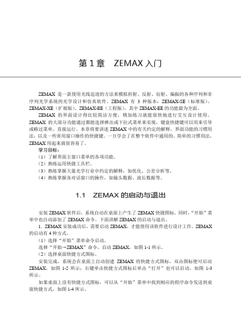
1.1 ZEMAX的启动与退出安装ZEMAX软件后,系统自动在桌面上产生了ZEMAX快捷图标。
同时,“开始”菜单中也自动添加了ZEMAX命令。
下面讲解ZEMAX的启动与退出。
1.ZEMAX安装成功后,需要启动ZEMAX,才能使用该软件进行设计工作。
ZEMAX 的启动有4种方式。
(1)选择“开始”菜单命令启动。
选择“开始→ZEMAX”命令,启动ZEMAX,如图1-1所示。
(2)选择桌面快捷方式图标。
安装完成,系统会在桌面上自动创建ZEMAX的快捷方式图标,双击图标便可启动ZEMAX,如图1-2所示;右键单击快捷方式图标后单击“打开”也可以启动,如图1-3所示。
如果桌面上没有快捷方式图标,可以从“开始”菜单中找到相应的程序命令发送到桌面快捷方式,如图1-4所示。
2第1章ZEMAX入门图1-1 “开始”菜单命令启动图1-2 桌面快捷方式图标图1-3 右击快捷方式启动图1-4 发送桌面快捷方式(3)选择快速方式启动。
单击任务栏快速方式图标也可以启动ZEMAX。
zemax 详细教程
Getting Started Using ZEMAX®Version 1.1.6Table of Contents1 2 ABOUT THIS GUIDE ......................................................................................................................................................... 3 INSTALLING ZEMAX ......................................................................................................................................................... 4 2.1 2.2 2.3 2.4 2.5 2.6 3 INSTALLING THE KEY DRIVER ........................................................................................................................................ 4 INSTALLING ZEMAX ..................................................................................................................................................... 4 LICENSE CODES ........................................................................................................................................................... 4 NETWORK KEYS AND CLIENTS ...................................................................................................................................... 5 TROUBLESHOOTING ...................................................................................................................................................... 5 CUSTOMIZING YOUR ZEMAX INSTALLATION .................................................................................................................. 6THE ZEMAX USER INTERFACE ...................................................................................................................................... 7 3.1 3.2 3.3 3.4 3.5 3.6 3.7 3.8 3.9 THE LENS DATA EDITOR ............................................................................................................................................... 7 ANALYSIS W INDOWS ..................................................................................................................................................... 9 THE SYSTEM MENU .................................................................................................................................................... 10 THE NORMALIZED COORDINATE SYSTEM ..................................................................................................................... 12 DEFINING & POSITIONING SURFACES........................................................................................................................... 14 W ORKING IN THREE DIMENSIONS ................................................................................................................................ 16 MULTIPLE CONFIGURATIONS ....................................................................................................................................... 18 EXPORTING TO MECHANICAL CAD PACKAGES ............................................................................................................. 24 SUMMARY .................................................................................................................................................................. 254OPTIMIZATION ............................................................................................................................................................... 26 4.1 4.2 4.3 4.4 4.5 4.6 4.7 4.8 4.9 THE LENS SPECIFICATION ........................................................................................................................................... 26 ENTERING THE BASIC SYSTEM .................................................................................................................................... 26 SETTING VARIABLES ................................................................................................................................................... 31 DEFINING THE MERIT FUNCTION.................................................................................................................................. 32 OPTIMIZING THE LENS ................................................................................................................................................ 33 THE HAMMER OPTIMIZER ............................................................................................................................................ 36 ARE THERE ENOUGH FIELD POINTS?........................................................................................................................... 37 GLASS OPTIMIZATION ................................................................................................................................................. 39 TIPS FOR SUCCESSFUL OPTIMIZATION......................................................................................................................... 41Page 1 of 725NON-SEQUENTIAL RAY TRACING (EE ONLY) ............................................................................................................ 43 5.1 5.2 5.3 5.4 5.5 5.6 5.7 A SIMPLE EXAMPLE .................................................................................................................................................... 43 OBJECT POSITIONING & DEFINITION ............................................................................................................................ 46 COMBINING SEQUENTIAL AND NON-SEQUENTIAL RAY-TRACING ................................................................................... 49 TRACING RAYS AND GETTING DATA ............................................................................................................................ 50 COMPLEX OBJECT CREATION ..................................................................................................................................... 54 OPTIMIZING NON-SEQUENTIAL SYSTEMS ..................................................................................................................... 56 COLORIMETRY ........................................................................................................................................................... 596POLARIZATION, COATINGS & SCATTERING (EE ONLY) .......................................................................................... 61 6.1 6.2 6.3 6.4 6.5 6.6 POLARIZATION............................................................................................................................................................ 61 THIN-FILM COATINGS ................................................................................................................................................. 62 RAY SPLITTING........................................................................................................................................................... 66 RAY SCATTERING ....................................................................................................................................................... 66 IMPORTANCE SAMPLING ............................................................................................................................................. 68 BULK AND FLUORESCENT SCATTERING ....................................................................................................................... 697WHAT’S NEXT? .............................................................................................................................................................. 71 7.1 GETTING TECHNICAL SUPPORT ................................................................................................................................... 72ZEMAX is a registered trademark of Radiant ZEMAX, LLC.Page 2 of 721 About This GuideCongratulations on your purchase of ZEMAX! ZEMAX is the industry standard optical system design software, combining sequential lens design, analysis, optimization, tolerancing, physical optics, non-sequential optical system design, polarization, thin-film modeling and mechanical CAD Import/Export in a single, easy-to-use package. Although ZEMAX is easy to use, optical system design is a very broad area of engineering. This guide is intended to get you started using ZEMAX quickly. It is the first place to start if you are new to ZEMAX, or if you are returning to it after having not used ZEMAX for some time. You may learn something even if you have used ZEMAX for many years! We strongly recommend you take the time to work all the way through this booklet. It covers:• • • • • • • • • • • • Installing ZEMAX, and customizing its appearance and file locations to your preference. Entering a simple sequential design Understanding the normalized definitions ZEMAX uses. An overview of the multiple configurations capability. How to export components and rays to mechanical CAD packages. Optimizing a simple lens. Using some of the powerful tools ZEMAX makes available. Tilting and decentering optical components. Entering a simple non-sequential system, tracing rays, and using detectors. Colorimetry. Thin-Film Coatings. Surface, bulk and fluorescent scattering.As well as getting you started, this guide also points you to some of the other resources you can use to learn ZEMAX. In particular, the User's Manual is a detailed reference on all aspects of ZEMAX. It is supplied in PDF format and is found in ZEMAX by clicking on Help Manual. This guide refers to the various chapters and sections of the manual as it goes along, as well as to some of the many sample files distributed along with ZEMAX. Also, our web-based Knowledge Base at /kb is an indispensible resource for all ZEMAX users. It contains tutorials, worked examples and answers to many frequently-asked questions.Page 3 of 722 Installing ZEMAXTo use ZEMAX, there are two programs that must be installed on your computer. The latest versions of both can be downloaded from /updates. The two programs are:• The ZEMAX installer, which has a name like ZEMAX_YYYY_MM_DD.exe, where YYYY, MM and DD are the year, month and day of the release. Different releases of ZEMAX are identified by their release date instead of a version number. The same installer is used for both ZEMAX-SE and ZEMAX-EE, and it contains all program files, sample files and a detailed User's Manual in PDF format. The key driver installer. ZEMAX is not copy protected, and may be installed on as many machines as you wish. ZEMAX is supplied with a black USB device which allows ZEMAX to run on the machine it is plugged into, and determines whether the SE or EE feature sets are available. A multi-computer network key is also available.•You must install both programs under a user account with Administrator privileges. Only Standard User privileges are needed to use ZEMAX once installation is complete.Note: The key supplied with the ZEMAX software is worth the full purchase price of the software. If the key is lost or stolen, it will not be replaced without payment of the full purchase price. Insure the key as you would any other business or personal asset of comparable value.2.1 Installing The Key DriverThe key driver installation is straightforward. Double-click the key driver installer once you have downloaded it, and choose the ‘Complete’ installation of all program features. A dialog box will also ask for your permission to modify the firewall settings of your computer to allow remote users of your computer to run ZEMAX using Remote Desktop. If you want to authorize this, click "Yes", otherwise click "No". To change this setting, just re-run the key driver installer. Plug the key in once the key driver installation is complete, and Windows will detect the hardware key. The green LED at the end of the key will illuminate.2.2 Installing ZEMAXThe installation of ZEMAX itself is similarly straightforward. Double-click the ZEMAX installer once you have downloaded it, and step through the on-screen instructions. You may choose where on your hard drive ZEMAX is installed.2.3 License CodesWhen ZEMAX runs for the first time, it may prompt you to enter a license code. If it does, visit /updates and download the file lc.dat by right-mouse-clicking the link, choosing 'Save Target As:' and storing in your ZEMAX installation folder, overwriting the current version. If after that, you continue to see a dialog box like so:Page 4 of 72Take a screenshot of this dialog box (use Alt-Print_Screen) and paste it into an email to support@. We will promptly send you the license code or further instructions.Note: Please do not phone for a license code! License codes are complex multi-character strings and cannot be reliably given over the phone. Emailing the screenshot of the dialog box to us is the quickest, most error-free way of getting your license code.2.4 Network Keys And ClientsZEMAX can also be supplied with 5, 10, 25 and 50-user network keys. Installation is almost identical, except that the key driver and hardware key are installed on one computer (called the ‘keyserver’ machine) and ZEMAX is installed on as many other machines as you wish (the ‘client’ computers). When a client machine starts ZEMAX, it looks to the keyserver machine to see if a license is available, and if so, ZEMAX starts. Installation of the key driver on the keyserver machine is identical to the normal installation, except that you obviously MUST allow the firewall settings to be adjusted to allow network access to the key. Installation of ZEMAX on the client machines is also identical to the normal installation, except that you must tell ZEMAX where to look for the keyserver machine after installation. Navigate to whatever folder you installed ZEMAX in (by default this is /program files/ZEMAX) and locate a file called sntlconfig.xml.bak. Rename this file to sntlconfig.xml, and open it in Notepad. Edit the following line: <ContactServer> 10.0.0.1 </ContactServer> Replace the default entry 10.0.0.1 with the IP address of your keyserver machine and save the file.2.5 TroubleshootingZEMAX will run without problem in the vast majority of cases. If you do experience problems, then visit our Knowledge Base at /kb. Look at the Category ‘Installation and Troubleshooting’ for help. Make sure your key is plugged in!Page 5 of 722.6 Customizing Your ZEMAX InstallationWhen ZEMAX starts for the first time, it loads a number of default settings which you may prefer to customize to your preference. Start ZEMAX, and click on File Preferences. A multi-tab dialog box will open:This allows you to set all the ‘installation-specific’ settings.Note: Full details of all Preference settings are given in the User's Manual, chapter 4 “File Menu” or can be obtained by pressing the Help button in the dialog boxes.You should explore all these tabs, but the most important ones are: 2.6.1 The Address Tab This is shown above, and it allows you to enter information about your organization which is then printed on most graphics windows. 2.6.2 The Directories Tab This tab defines the folders that ZEMAX will use for the various file types it needs. They can be redirected wherever you wish by pressing the ? button for any path and navigating to the desired location. 2.6.3 The Editors Tab This tab allows you to adjust the appearance of the various Editors that ZEMAX uses. Adjusting the ‘Decimals’ setting affects how many decimal places ZEMAX displays in the Editor cells, but does not affect the accuracy of the data itself. All data is stored in ZEMAX as double-precision floating point numbers. Selecting "Compact" will vary the number of decimals displayed to minimize the space required to display numbers, so that trailing decimals are not displayed unless necessary. You can change the font, font size, and cell widths of all the editors.Page 6 of 723 The ZEMAX User InterfaceStart ZEMAX, and open the sample file “samples/sequential/objectives/Double Gauss 28 degrees field”. Even if you intend to use only the non-sequential mode of ZEMAX you should still follow this example, as the user interface is common to both sequential and non-sequential ray-tracing. The user interface consists of three main elements:1.The program ‘frame’ that consists of the menu strip and toolbar at the top, and a status bar at the bottom. An editor spreadsheet, in this case the Lens Data Editor. Almost all data is entered via editors, which allow the parameters that define the optical system to be easily seen, and linked together or optimized as required. Data that is rarely modified once set is entered elsewhere, as we will discuss later. For now, note that the Lens Data Editor shows a sequence of ‘Standard’ surfaces which have radius of curvature, thickness, glass type, Semi-diameter and conic constant. There are then a series of parameters, labeled 0 through 12, which are not used by this surface type, and finally a Thermal Coefficient of Expansion (TCE) column, and a coating column (for EE use only). Each surface in this lens has coating ‘AR’, which is a quarter-wave thick MgF2 coating. Analysis windows, which are the results of some calculation the program has performed. In this case, the 2-D Layout, RMS Wavefront error versus field plot, and Spot Diagram are shown.2.3.Before proceeding, click on Tools Miscellaneous Performance Test and click Run TestThis will give you a simple metric of how fast ZEMAX is on your computer. It also shows one of the best features of ZEMAX: its ability to use multiple CPUs in your computer, if available. Calculations are split up and spread over all available CPUs, and the results stitched back together again, without any user interaction.3.1 The Lens Data EditorIn sequential ray-tracing, light is traced from its source, called the ‘Object’ surface, to surface 1, then to surface 2, 3, etc. until it lands on the final ‘Image’ surface. For historical reasons this surface is always called the Image surface, even though the optical system may not form an image of the source. A laser beam expander or eyepiece for example may be afocal: this is covered later. Surfaces are inserted or deleted in the editor using the Insert or Delete keyboard keys, or via the ‘Edit’ menu which also allows individual cells or the entire spreadsheet to be copied to the clipboard. Column widths can be varied by placing the cursor in the top row, over the column separator. When the cursor turns to a ↔ symbol, click and hold the left mouse button to resize the column. Columns and rows can be hidden entirely (and unhidden) using the View menu.Page 7 of 72The ‘V’ next to some parameters means that this parameter is ‘variable’. ZEMAX is allowed to change the values in such cells in order to improve the performance. This will be discussed in more detail later.Surfaces also have a set of properties that are not directly visible in the editor. These are generally those properties that are set and then not changed. To see these properties, move the mouse over the Type cell of the chosen surface, and double click. Alternatively, click anywhere on the chosen row, and choose Edit Surface Type. A multi-tab dialog appears. From the Surface Type drop-down list you can select the type of the surface, which can be aspheric, diffraction grating, toroidal, etc.Note: See the User's Manual Chapter 11, “Surface Types” for full details of all the surface types that ZEMAX supportsSpend some time exploring each tab. The most commonly used tabs are the Type, Draw, Aperture and the Tilt/Decenter tabs. Press the Help button on each tab to read the on-line Help.Note: Chapter 5 of the User's Manual, “Editors menu”, gives full details of all the Editors and their properties.Page 8 of 723.2 Analysis WindowsAnalysis windows provide either graphical or text-based data computed from the lens as entered in the Editor. Analysis windows never change the lens data: they provide diagnostic information of the various aspects of the lens system’s performance. Analysis windows all operate with the same user interface:• • • Pressing the Update menu item, or double-clicking anywhere in the Analysis window with the left mouse button, will make the Analysis window recompute. Pressing the Text menu item will show the underlying data that is being presented graphically. The Window menu item gives you access to Copy, Export as Bitmap, Export as Text File, etc. options.A typical Analysis window is shown opposite. All Analysis windows share the same menu bar. You can zoom in on a section of interest by clicking the left mouse button, holding it down and dragging it over the region you wish to zoom in on.Note: Chapter 7 of the User's Manual, “Analysis Menu”, gives full details of all Analysis windows.Clicking the Settings menu item, or right-mouse-clicking anywhere in the Analysis window, will bring up the Settings dialog box:The layout of this box will depend on the Analysis feature used, of course. The Settings are used to control the calculation. Pressing OK will recompute the Analysis calculation. The Save, Load and Reset buttons allow default settings to be saved, recalled or reset to ‘factory’ defaults. If you save the settings of any window, those become the defaults for every file that does not have its own settings, so your preferences automatically flow through all your work. The Help button will bring up the on-line help for the window.Page 9 of 723.3 The System MenuIn addition to the surfaces of the optical system, we must also define the light that is incident on the optical system. This is done with the System menu:Or with these buttons on the button bar:3.3.1 The General Dialog Box The General dialog box contains settings that apply to the whole lens design. The most important tab is the Aperture tab, which defines how big the bundle of light coming into the lens on-axis is:In this case, we define the Entrance Pupil Diameter to be 33.33 ‘lens units’. Click on the ‘Units’ tab to see that millimeters are the defined lens units in this file. Other options arePage 10 of 72meters, centimeters, and inches. Once the lens units are defined, any length where the units are not explicitly given is in lens units. Entrance Pupil Diameter (EPD) defines the size of the on-axis bundle of light entering the lens system. In the double-Gauss sample file we are using, which is a traditional SLR-type camera lens, ZEMAX traces rays at this height through the lens and computes the size of the aperture stop surface (marked as STO in the Lens Data Editor), drawn in red opposite. The aperture stop surface is usually a ring diaphragm, so in reality the radial size of this surface defines the EPD, not the other way around. If you prefer this alternative definition, then choose the Aperture Type in the General dialog box to be ‘Float by Stop’, and then change the semi-diameter of the STO surface to say 8 mm. Double-click all the open Analysis windows to make them update to reflect this change, and notice the change in the lens apertures and performance. ZEMAX automatically computes the appropriate size of each surface so that all light passes through each surface. Another commonly used Aperture Type is ‘Object Space NA’ which is appropriate when the source is something like an optical fiber that radiates out in a defined numerical aperture. Use ‘Object Cone Angle’ if the source is defined by a source angle in degrees instead of NA. There are other definitions available for less common requirements, and several other tabs that define ‘system level’ settings for the file. Review these with the on-line Help, or see Chapter 6 of the User's Manual for full details. 3.3.2 The Field Dialog Box The term “Field” is short for field-of-view and it can be defined in three ways, one of which supports two options:• •The height of the object scene being imaged The height of the image being formed, which may be chosen to be either a real or paraxial image height The angle subtended by the object scene at the lens•Whichever you choose, it is defined by System Field, or by pressing the ‘Fie’ button:Page 11 of 723.3.3 The Wavelength Dialog Box The wavelengths dialog box, defined under System Wavelength or by pressing the ‘Wav’ button, is used to set wavelengths, weights, and the primary wavelength of the system.Wavelengths are always entered in microns. Wavelength weights can be used to define relative spectral intensity, or simply to define which wavelengths are most important in a design. The ‘primary’ wavelength is used as a default wavelength: for example, if asked to compute effective focal length, ZEMAX will compute it at the primary wavelength if no wavelength is specified.3.4 The Normalized Coordinate SystemBecause there are six ways to define system aperture, and four ways to define field of view, it is convenient to work in normalized coordinates. When performing the initial setup of your system you should choose the most appropriate aperture definition, and the most appropriate field definition, and enter the data for both of these. Subsequently, all calculations use normalized units, and you do not have to refer to the specific values entered or definitions used. 3.4.1 Normalized Field Coordinates Normalized field coordinates Hx and Hy are used throughout ZEMAX, its documentation, and in the wider optical design literature. The normalized field coordinate (0, 1), for example, is always at the top of the field of view in y, whether the field points are defined as angles or heights, and regardless of the magnitude of the field coordinates. Similarly the field coordinate (0,0) is always at the center of the field of view. For example, suppose 3 field points are defined in the (x, y) directions using object height in lens units of millimeters at (0, 0), (10, 0), and (0, 3). The field point with the maximum radial coordinate is the second field point, and the maximum radial field is therefore 10 mm. The normalized coordinate (Hx =0, Hy = 1) refers to the location on the object surface (as the field of view is defined in object height) of x= 0, y =10 mm. The normalized coordinate (Hx = 1, Hy = 0) refers to the object surface location (10, 0). You can then define any point within the field of view of the lens by its (Hx, Hy) coordinates, as long as Hx2 + Hy2 ≤ 1. This is referred to as radial field normalization, as the normalized field coordinates represent points on a unit circle. ZEMAX also supports rectangular field normalization, in which the normalized field coordinates represent points on a unit rectangle.Page 12 of 72Note: See the User's Manual, chapter 3 “Conventions and Definitions”, for full details of these conventions and all the basic definitions ZEMAX uses.3.4.2 Normalized Pupil Coordinates Similarly, normalized pupil coordinates are also used throughout ZEMAX, its documentation, and in the wider optical design literature. You define the system aperture using whatever definition is most useful, and thereafter we use the normalized pupil coordinates Px and Py to define any point within a unit circle. Therefore, the point (0,1) represents a point at the top of the bundle of rays entering the system, and (0, 0) is a point at the center of the ray bundle, no matter what the definition of system aperture is or what value it has. 3.4.3 Using the Normalized Coordinates Re-open the double Gauss 28 degree field sample file in order to undo any changes you may have made in the earlier sections. Open the Field dialog box and note that the field is defined as angle in degrees, and the maximum field point has a value of 14°. This is a half-angle, and so the full field of view is 28°.Note: ZEMAX is always clear on the definitions it uses, but these definitions are not universal in the optics industry. Always clarify with your customers what definitions they use for important system specifications to avoid costly errors!Then open the General dialog box, and under the aperture tab note that the system aperture is defined as Entrance Pupil Diameter, value 33.33. Go to the Units tab to see that the lens units are millimeters, so the EPD is 33.33 mm. Lastly, open the Wavelength dialog box and note that the design uses three wavelengths, at 0.4861, 0.5876 and 0.6563 microns respectively. The primary wavelength is set as wavelength number 2, which is 0.5876 microns. Now click on Analysis Calculations Ray Trace. This is the most fundamental calculation in ZEMAX: the tracing of a single ray. Right-mouse click on this window to bring up its Settings dialog box:Page 13 of 72。
[整理版]zemax手把手教程
![[整理版]zemax手把手教程](https://img.taocdn.com/s3/m/4982d38a767f5acfa0c7cd5c.png)
[整理版]zemax手把手教程ZEMAX手把手教程课程1:单透镜(a singlet)你将要学到的:开始ZEMAX,输入波长和镜片数据,生成光线特性曲线(ray fan),光程差曲线(OPD),和点列图(Spotdiagram),确定厚度求解方法和变量,进行简单的优化。
假设你需要设计一个F/4的镜片,焦距为100mm,在轴上可见光谱范围内,用BK7玻璃,你该怎样开始呢,首先,运行ZEMAX。
ZEMAX主屏幕会显示镜片数据编辑(LDE)。
你可以对LDE窗口进行移动或重新调整尺寸,以适合你自己的喜好。
LDE由多行和多列组成,类似于电子表格。
半径、厚度、玻璃和半口径等列是使用得最多的,其他的则只在某些特定类型的光学系统中才会用到。
LDE中的一小格会以“反白”方式高亮显示,即它会以与其他格子不同的背景颜色将字母显示在屏幕上。
如果没有一个格子是高亮的,则在任何一格上用鼠标点击,使之高亮。
这个反白条在本教程中指的就是光标。
你可以用鼠标在格子上点击来操纵LDE,使光标移动到你想要停留的地方,或者你也可以只使用光标键。
LDE 的操作是简单的,只要稍加练习,你就可以掌握。
开始,我们先为我们的系统输入波长。
这不一定要先完成,我们只不过现在选中了这一步。
在主屏幕菜单条上,选择“系统(System)”菜单下的“波长(Wavelengths)”。
屏幕中间会弹出一个“波长数据(Wavelength Data)”对话框。
ZEMAX中有许多这样的对话框,用来输入数据和提供你选择。
用鼠标在第二和第三行的“使用(Use)”上单击一下,将会增加两个波长使总数成为三。
现在,在第一个“波长”行中输入486,这是氢(Hydrogen)F谱线的波长,单位为微米。
ZEMAX全部使用微米作为波长的单位。
现在,在第二行的波长列中输入587,最后在第三行输入656。
这就是ZEMAX中所有有关输入数据的操作,转到适当的区域,然后键入数据。
在屏幕的最右边,你可以看到一列主波长指示器。
2024版光学设计软件Zemax中文教程

在Zemax中引入偏振器件,如偏振片、波片 等,进行光学系统的偏振设计。
通过仿真分析,评估偏振设计对光学系统性 能的改善程度。
自定义操作数编写技巧
了解自定义操作数基本概念
自定义操作数是指用户根据实际需求,在 Zemax中自定义的光学性能评价指标。
调试自定义操作数
在编写过程中,需要对自定义操作数进行调试和 验证,确保其正确性和可靠性。
它具有强大的光学仿真功能,可以模拟各种光学现象,如光的传播、反射、折射、 散射等。
Zemax还提供了丰富的光学元件库和优化的算法,使得用户可以更加高效地进行光 学设计。
软件安装步骤及注意事项 01
下载Zemax安装程序,并双击运行。
02
按照提示完成软件的安装过程,注 意选择正确的安装路径和组件。
安装完成后,需要激活软件,输入 正确的许可证密钥。
02 智能化、自动化将成为光学设计的重要发 展方向。
03
新材料、新工艺的不断涌现将为光学设计 提供更多可能性。
04
光学设计将与机械、电子、计算机等多学 科进一步交叉融合。
下一讲预告及预备工作
下一讲将介绍光学系统 的公差分析与优化方法。
01
02
建议学员多阅读相关文 献和资料,加深对光学 设计理论的理解。
属性栏显示了当前选中对 象的各种属性,用户可以 在这里进行修改和调整。
设计区域是用户进行光学 设计的主要场所,可以在 这里绘制和编辑光学系统。
初学者常见问题解答
问题1
01
如何启动Zemax软件?
解答
02
双击桌面上的Zemax图标或者在开始菜单中找到Zemax程序并
单击启动。
问题2
03
如何新建一个光学设计项目?
【ZEMAX光学设计软件操作说明详解】

【ZEMAX光学设计软件操作说明详解】第二章用户界面概述本章介绍了对ZEMAX用户界面进行操作的一些习惯用法,以及一些常用的窗口操作的快捷键。
一旦您学会了在整个程序中通用的简单的习惯用法,ZEMAX用起来就很容易了。
在线教程中,也有逐步学习ZEMAX使用方法的例子。
视窗的类型ZEMAX有不同类型的窗口,每类窗口完成不同的任务。
这些类型有:1、主窗口:这个窗口有很大的空白空间,顶端有标题栏,菜单栏和工具栏。
菜单栏中的命令通常与当前的光学系统相联系,成为一个整体。
2、编辑窗口:有六种不同的编辑1)透镜数据编辑;2)绩效函数编辑;3)多重结构编辑;4、额外数据(ZEMAX-EE);5)公差数据编辑;和非顺序组件编辑(ZEMAX-EE)。
3、图形窗口:这类窗口用作呈现图像数据,例如:系统图;光线扇形图(Ran fan);光学传递函数(MTF);曲线(Dot Spot)……等等。
4、文本窗口:用来列出文本数据,例如:指定数据、像差系数、计算数据等。
5、对话窗口:对话框是弹出窗口,不能改变大小。
对话窗口用来改变选项和数据,如:视场;波长;孔径光阑;表面类型等。
在图像和文本窗口中,对话框也被广泛地用来改变选项,比如改变系统图中光线的数量。
除了对话框,所有窗口都能通过使用标准鼠标这键盘按钮进行移动和改变大小。
如果你对这些方法不熟悉,请参考有关Windows使用的书籍或者Windows的说明书。
主窗口的操作方法主窗口栏有几个菜单标题。
大部分菜单标题与这本手册后面的章节标题相对应。
从这些章节能够找到使用每一菜单项的具体方法。
以下是菜单的标题:File:用于镜头文件的打开、关闭、保存、重命名;Editors:用作调用(显示)其他的编辑窗口;System:用于确定整个光学系统的属性;Analysis:分析中的功能不是用于改变镜头数据,而是根据这些数据进行数字计算和图像显示分析。
包括:系统图(Layout)、Ray fans,Spot diagrams,Diffraction calculations and more。
- 1、下载文档前请自行甄别文档内容的完整性,平台不提供额外的编辑、内容补充、找答案等附加服务。
- 2、"仅部分预览"的文档,不可在线预览部分如存在完整性等问题,可反馈申请退款(可完整预览的文档不适用该条件!)。
- 3、如文档侵犯您的权益,请联系客服反馈,我们会尽快为您处理(人工客服工作时间:9:00-18:30)。
Session file的概念
Session file :在保存文件时,如果选择Session file,则它包括lens file, 所有图形和文本窗口,editors,它们在屏幕上的大小和位置, 及每个窗口的设置。此时,除了一个ZMX文件以外,还有一个SES 文件。
Lens Data
Lens data的组成
NSC without ports system例子
ZEMAX用户界面
ZEMAX用户界面类型
ZEMAX有4种主要类型的用户界面:
Editors:定义和编辑光学面和其他数据; Graphic windows:显示图形数据;
Text windows:显示文本数据;
Dialog boxes:编辑和回顾其他窗口或系统的数据,或者报告错误信 息等。
steven:
Text windows菜单功能
Text:产生图形所对应的文本数据; Zoom:对图形放大和缩小控制 Update:更新窗口中的数据; Setting:设置窗口的属性; Print:打印窗口的内容; Windows: Copy clipboard:将内容拷贝到剪切板中; Save: 保存ASCII TXT文件; Lock:锁定窗口; Clone:Clone窗口; Configuration:选择要显示哪个结构的数据;
传统的镜头设计,和大多数成像系统;
Hybrid sequential/ non-sequential(aka NSC with ports) 同时有sequential组件和non-sequential组件(如prism,pipe)的 系统; 用“ports‖为光线进入和离开NS group的出入口; Purely non-sequential(aka NSC without ports) 用于illumination,scattering,stray light analysis; 不用“ports‖。
ZEMAX Editors界面
有很多种: Lens data editor: 基本的lens data,包括surface type, radius, thickness, glass,etc. Merit function editor:优化时,定义和编辑merit function; Multi-Configuration editor:为变焦镜头和其它多重结构系统定义多重 结构参数; Tolerance Data editor:定义和编辑公差数据; Extra Data editor:需要很多参数的surface data的扩展; Non-sequential component editor:定义和编辑NSC sources, objects, detectors。
Surface data的组成
The radius of curvature:面的曲率半径,根据符号规则确定符号; The thickness of the surface:到下个面的相对距离,满足符号规则 (用local坐标系); The glass type of the surface:可以直接输入玻璃的名称,也可以输 入折射率和色散系数(如果是空气,则为空格); The semi-diameter of the surface(optional):面的孔径; Other data(parameter or extra data):描述面形的参数。
ZEMAX Editors
Graphic and Text 界面
有些功能(如layout)只支持图形,有些只支持文本(如Seidel 像差系数),有的都支持(如fan plot); 如果二者都支持,一般先给出图形输出,如果需要显示text的内 容,需要点一下菜单栏中的“Text‖;
Graphic and Text windows例子
大部分图形窗口都提供文本信息。
Graphic and Text windows例子
点Text菜单栏,可以看到图形窗口中的文本信息。
Graphics windows菜单功能
Update:更新窗口中的数据; Setting:设置窗口的属性; Print:打印窗口的内容; Windows: Annotate:往图形上加lines,boxes,text; Copy clipboard:将内容拷贝到剪切板中; Export:将内容转换为WMF,EMF,JPG,BMP文件保存; Lock:锁定窗口; Clone:Clone窗口; Aspect ratio:设置窗口的长宽比; Active cursor:对图形窗口显示鼠标所指位置的数据; Configuration:选择要显示哪个结构的数据; Overlay:不同图形重叠显示;
NSC with ports system例子
Ray Tracing的3种方式(III)
(3) Purely Non-sequential(aka NSC without port) •所有object都是3D shell or solids; •每个object都在一个空间坐标系中定义了其特性; •需要定义光源的发光特性和位置,定义detector收集光线; •光线一直追迹,直到它遇到下列情况才终止: Nothing, 能量低于定义的阈值。 •计算时光学元件的相对位置由空间坐标确定;对同一元件,可同时进 行穿透、反射、吸收及散射的特性计算; •无法作优化及公差分析; 这种情况下,可以对光线进行分光,散射,衍射,反射,折射。
(2)还提供了User Defined Surface。用户只需要按照它的语法规定, 用C++语言编写DLL文件与ZEMAX相连接就可以建立自己需要的面形。
The system aperture
它是很重要的一个参数,决定入瞳的大小,它决定光学系统在物 空间收集多少光线。
System aperture types
Dialog boxes
ZEMAX的大部分图形和文本窗口都包含有设置对话框。
数据输出
输出到到剪贴板,可以再到其它windows应用程序,如Excel等; 输出到CAD程序:支持DXF,IGES,STEP,SAT格式。 DXF: 因为不是标准格式,对其支持比较差一些; 只有在wireframe的设定中才支持。 IGES,STEP,SAT: 真正的标准; 可以输出3D solids; 可以输出为lines; 在Tool菜单栏中。
Zemax使用群
※NASA美国太空总署,Sandia 国家实验室, U.S.Army军队, HP, Motorola…
※台湾:电子所,中科院,大学…以及扫描仪,相机,望远镜,投影机等制 造商. ※大陆:光学、光电研究所,大学,光学公司,光学加工厂,从事光 学镜头、条形码、投影仪、背投影电视、光通信器件、VCD及DVD读 写头等的设计的公司。
•Entrance Pupil Diameter(EPD):直接指定入瞳的大小; •Image Space F/#:无限共轭像空间近轴F数(f/D,只用于物距无穷远); •Object Space Numerical Aperture:物空间边缘光线的数值孔径nsinθ (物在有限远处,保持N.A.为常数); •Float by Size:EPD的大小由光栏的半径决定; •Paraxial working F/#:像空间中定义的共轭近轴1/2ntan,忽略像差;
系统要求
WIN98,NT,2000,XP 200Mb 以上的硬盘空间 最小的分辨率为:1024*768 一个并行口或者USB接口用来接KEY 64Mb以上内存;如果进行对象非常复杂、物理光学或散射和照
明分析时,最低要求是256MB,最好是512Mb
What is ZEMAX
ZEMAX是一个光学设计软件,它使用sequential和non-sequential的 方法模拟refractive,reflective和diffractive光线追迹。 ZEMAX用“surface‖为sequential ray tracing建模;用“component‖ 或solid object model为non-sequential ray tracing建模。 Purely sequential :
ZEMAX简介(II)
界面友好,容易上手;资料丰富,既可以直接选择,又可以自定义; 可建立反射、 折射、衍射及散射等光学模型; 可进行偏振、镀膜和温度、气压等方面的分析
具有强大的像质评价和分析功能;
丰富的资料库,有现成的镜头和玻璃、样板数据,可供用户选择; 大部分窗口都提供在线帮助,方便随时获取相关功能的在线解释和帮助;
steven: steven:
ZEMAX软件培训教程
国内外光学设计软件情况
※国内情况: • 北京理工大学(SOD),南京理工大学等自编光学设计软件。 ※国外情况: • Optical Research Associates: Code V
•
Lambda: OSLO等。
ZEMAX已经成为当今使用最普遍的光学 设计软件
※ 市场占有率:80~85%
※ 全球已经销售了两万多套
※ 台湾已经销售600多套 ※ 大陆已经有300多套,知道和需要购买者越来越多
市场应用
※ 应用范围: • 传统相机、数码相机、内窥镜等光学镜头的设计 • DVD、VCD读写头 • 投影系统,背投电视 • 照明系统 • 干涉仪
• LED
• Laser diode • 光通信器件设计等等„
Sequential system例子
Ray Tracing的3种方式(II)
(2)Hybrid sequential/non-sequential(aka NSC with ports) •所有object都是3D shell or solids; •每个object都在一个空间坐标系中定义了其特性; •光线从input port进入non-sequential group;从exit port 离 开NS group; •光线在NSC中一直追迹,直到它遇到下列情况才终止: Nothing Exit port 能量低于定义的阈值。 •忽略NS group内的光源和探测器; •进入NS group的光线的特性,由序列性的系统数据,如视场位置和 瞳的大小等决定。