MOXA串口设备服务器NPort 5232 注意事项
MOXA串口服务器中文使用文档

MOXA串口服务器中文使用文档一、引言二、安装1.要开始使用MOXA串口服务器,首先需要将设备连接到计算机上。
将设备的以太网端口连接到计算机上的以太网接口,并将串行设备连接到设备的串口接口。
2.将设备的电源适配器插入电源插座,并将适配器的连接线插入设备的电源接口。
3.打开计算机上的浏览器,输入设备的IP地址,在浏览器中打开设备的管理界面。
三、配置1.在设备的管理界面中,点击"配置"选项卡,进入设备的配置界面。
2.在配置界面中,可以配置设备的网络设置、串口配置和其他高级设置。
3.首先要配置设备的网络设置,包括IP地址、子网掩码、网关等信息。
确保设备的网络设置与计算机的网络设置相匹配,以便能够正确地连接到网络。
4.然后要配置设备的串口设置,包括波特率、数据位、停止位、校验位等信息。
根据需要配置串口的参数,以确保与串行设备的通信正常。
5.在完成网络和串口配置后,可以进行其他高级设置,如用户管理、安全设置、升级固件等。
根据需要进行相应的配置。
四、使用1.配置完成后,可以通过网络连接到MOXA串口服务器,并与串行设备进行通信。
2.打开计算机上的终端模拟程序,使用串口连接到设备的IP地址和端口号。
3.在终端模拟程序中,可以通过串口与串行设备进行交互。
发送命令或数据到串行设备,并接收串行设备返回的响应。
4.可以使用终端模拟程序提供的功能来控制串行设备,如发送命令、接收数据、保存日志等。
五、注意事项1.在使用MOXA串口服务器时,要确保设备的网络设置和串口设置正确无误,以确保与串行设备的通信正常。
2.在与串行设备进行通信时,要注意设备的串口配置与串行设备的要求相匹配,以确保数据的正确传输。
3.在进行高级设置时,要谨慎操作,避免对设备的正常运行产生不良影响。
六、总结本文档介绍了MOXA串口服务器的安装、配置和使用方法。
通过按照文档中的步骤进行操作,用户可以成功地将串行设备连接到网络,并实现与串行设备的通信。
MOXA NPort Express TCP IP 到 RS-232 服务器用户手册说明书
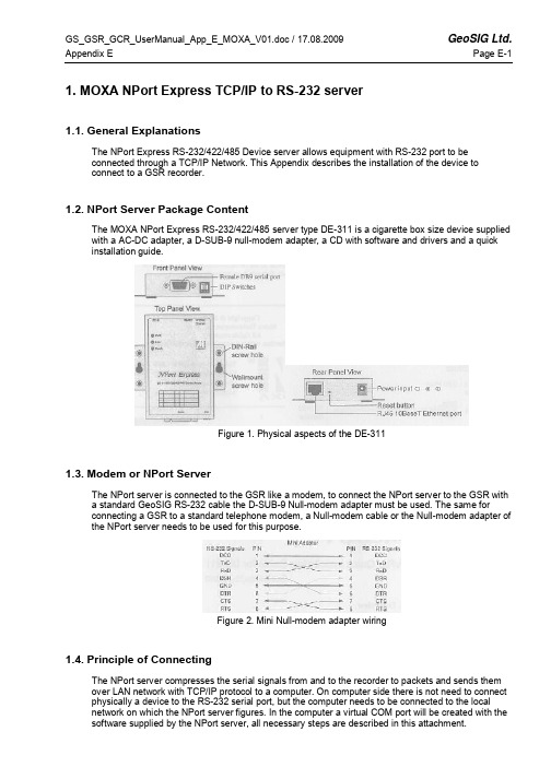
1. MOXA NPort Express TCP/IP to RS-232 server1.1. General ExplanationsThe NPort Express RS-232/422/485 Device server allows equipment with RS-232 port to beconnected through a TCP/IP Network. This Appendix describes the installation of the device toconnect to a GSR recorder.1.2. NPort Server Package ContentThe MOXA NPort Express RS-232/422/485 server type DE-311 is a cigarette box size device supplied with a AC-DC adapter, a D-SUB-9 null-modem adapter, a CD with software and drivers and a quick installation guide.Figure 1. Physical aspects of the DE-3111.3. Modem or NPort ServerThe NPort server is connected to the GSR like a modem, to connect the NPort server to the GSR witha standard GeoSIG RS-232 cable the D-SUB-9 Null-modem adapter must be used. The same forconnecting a GSR to a standard telephone modem, a Null-modem cable or the Null-modem adapter of the NPort server needs to be used for this purpose.Figure 2. Mini Null-modem adapter wiring1.4. Principle of ConnectingThe NPort server compresses the serial signals from and to the recorder to packets and sends them over LAN network with TCP/IP protocol to a computer. On computer side there is not need to connect physically a device to the RS-232 serial port, but the computer needs to be connected to the localnetwork on which the NPort server figures. In the computer a virtual COM port will be created with the software supplied by the NPort server, all necessary steps are described in this attachment.1.5. Configuring the NPort ServerFollowing steps must be done to establish a connection between computer and GSR1.5.1. Recorder Side (NPort Server)•Set 3 dip switches on NPort Server to OFF (low)•Connect NPort server to the GSR with the standard RS-232 cable supplied and use the Null-Modem mini adapter•Connect NPort server to the network with a standard RJ45 cable (Cable is not supplied in shipment)•Connect the AC-DC adapter, or another 12 VDC supply(Warning, with the AC-DC adapter the network communication is lost during a mains power failure) •When Power is available the 3 LED on the front of the NPort server must be on after approximately10 seconds (PWR: Red, Link: Green, Ready: Green) If not then refer to the MOXA manual1.5.2. Computer Side•Insert the MOXA installation CD into the computer, a menu will appear, press “Installation”•Choose all utilities to be installed like belowFigure 3. Installation Select Utilities•Continue installation and keep default settings•Choose to run configurator (Default) and finish installation)(Configurator can be launched from the start menu à Programs à NPort Management SuiteFigure 4. Installation Configure NPort Settings•The configurator application is now started•In configurator choose indicated button for a broadcast search, the network will be searched and all available NPort servers will be shownFigure 5. ConfiguratorFigure 6. Configurator after broadcast search•The factory default IP address of the NPort server is static and set to 192.168.127.254, to set up the correct device refer to the serial number that figures on the bottom of the device.1.5.3. Configuration of the Device•Now the device is visible on the network it must be set up therefor execute following steps:•Note: In case of trouble the device can be reset with pressing for more than 10 seconds on the reset button, factory defaults will be restored.•Double click on the row of the device to be set up, following window will pop upFigure 7. Configuration of NPort Server•Select the setting that need to be changed, the textbox next to will become active.•Depending on the network, either choose a static IP address, or select an IP configuration (For example DHCP if such server is available on the network). It is important to choose a correct IPaddress, please ask to your local network administrator who can tell which setting to use. For usinga direct connection to the computer the best option is to use directly the serial port. In case of ademo a direct connection from the NPort server to the computer is possible, but needs a crossedRJ45 cable. In direct connection static IP addresses for computer and NPort server must be used. Check the first three blocks of the IP Address, usually for local networks the first two are: 192.168, the third value can change between 0 and 255 and should be the same as the one on the computer. The fourth value is the subscriber number, avoid duplicate IP Addresses on one network that result in conflicts.•Add a server with the second menu button•Follow the steps of installing▪à Best to search automatically the LAN for an IP Address▪à In the displayed list choose the right NPort by help of the name, serial number or IP address if known•Select NPort you wish to connect to•Choose the COM port (Best way is to choose the next free port)Figure 10. Choose COM Port•Continue with scrolling with default settings until you come back in the Real COM Installer• A new device has been addedFigure 11. Real COM Installer, with new device•No further operations are needed, properties can be viewed by double clicking on the device•Application can be closed•Start GeoDAS and configure the GSR recorder as described in the GeoDAS manual1.6. Working behind NAT router to private IPIf you want to allow NPort to use private IP behind your NAT/firewall, you should use NAPT protocol to map the Public IP to NPort's private IP in your NAT router. Most of routers/firewalls all support this function now. For example, when you configure NPort's private IP as 192.168.1.1, and the NATrouter's Public IP is 61.x.x.x. Next, you should map TCP/UDP port numbers shown as follow:Protocol Public IP Port No. NPort Private IP Port No.TCP 61.x.x.x 23 192.168.1.1 23TCP 61.x.x.x 4000 192.168.1.1 4000TCP 61.x.x.x 950 192.168.1.1 950TCP 61.x.x.x 966 192.168.1.1 966UDP 61.x.x.x 1029 192.168.1.1 10291.7. TroubleshootingIn case GeoDAS reports an error accessing the GSR, and the correct COM port is selected, theproblem is in most of the cases in the assignment of IP addresses. Verify in such case that the first three groups of values in the IP address of the device are the same as the ones on the computer, and that there is no conflict with another subscriber.1.8. Further SettingsFor further settings please refer to the user manual on the CD supplied with the NPort server.。
连接串口服务器时的注意事项

连接串口服务器时的注意事项随着科技的快速发展,物联网的技术也不断更新换代,导致许多串口设备的全部潜力还没有得到充分利用。
然而,在工业物联网(IIoT)时代,网络管理者从串口设备中获取更多价值的时机变得越来越不合时宜。
实现此目的的一种方法是将设备连接到Internet,以从现有进程中提取未开发且可能有价值的信息。
许多应用程序已经获得了将其串口设备集成到基于IP的网络的好处,因为以前未开发的信息已被解锁以帮助简化和优化操作。
将串口设备连接到Internet有很多优点,但您应该提前计划。
在本文中,我们强调了在实现复杂的串口到以太网应用程序时非常重要的三个功能。
连接(也称为串口到以太网转换器)可用于将传统串口设备连接到基于以太网的网络。
串口服务器有两个接口:一侧是串口接口,另一侧是以太网接口。
串口设备服务器使用虚拟COM端口概念,允许来自传统串口设备的数据通过网络传输到现有的SCADA系统。
此外,串口设备服务器还支持原始套接字模式,它将串口数据透明地打包到TCP或UDP 数据包中。
大多数SCADA系统和OPC服务器都支持以太网封装驱动程序,它们与串口服务器一起使用以接收专有协议。
您仍然需要像以前一样手动处理协议,但串口服务器可以帮助您轻松地将数据传输到以太网。
使用串口服务器支持物联网云应用时需要考虑三个关键点:(1)多轮询,(2)专有协议,(3)带宽。
1.专有协议由于许多串口设备使用专有协议,因此设备服务器必须能够将串口数据正确转换为以太网数据包。
许多串口设备服务器支持原始套接字和TCP服务器模式,可以处理这些类型的转换。
然而,问题是串口设备服务器可能不知道将串口数据分成单独的TCP数据包的最佳方法。
串口服务器不了解专有的串口数据格式,因此它们可能会将串口设备的单个响应分解为两个或更多TCP数据包。
当SCADA系统或云应用程序解包数据包时,它们将被拒绝,因为单个数据包提供的串口数据不符合预期的格式。
SCADA系统或云应用程序通常希望将单个串口设备服务器响应打包到单个TCP数据包中。
MOXA串口服务器调试规范(Real COM Mode)

MOXA串口服务器调试规范(Real COM Mode)一、前言总结目前现场调试的经验,为减少调试过程中出现问题的机率,防止因串口服务器配置不正确,影响工程项目调试进展,现发布MOXA串口服务器调试规范.二、串口服务器参数配置MOXA串口服务器需配置的参数有以下几个:◆串口服务器名称◆串口服务器IP及掩码◆串口服务器工作模式以下分别介绍具体配置方法:1.串口服务器名称参见“设备基础参数分配策略”中,关于名称的规范要求,在“串口服务器”配置界面中按要求填写名称。
2.串口服务器IP及掩码参见“设备基础参数分配策略”中,关于IP及掩码的规范要求,在“串口服务器”配置界面中按要求填写IP及掩码。
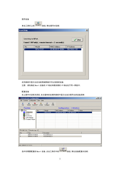
3.串口服务器工作模式●运行“NPort Administrator”程序,程序主界机如下图:●点击工具栏中按钮,搜索当前在线的“串口服务器”。
搜索完成后,将在列表中显示当前搜索到的“串口服务器”。
如准备配置的“串口服务器”未搜索到,请检查与设备网络联接是否正常。
●在列表中,双击需配置的“串口服务器”,弹出串口服务器配置窗体,如下图●点击“Operating mode”标签页,界面如下图:●勾选“Modify”,然后双击列表中第一项,弹出”工作模式”配置界面,如下图在“Operating Mode”下拉列表中,选择“Real COM Mode”,下方会显示该工作模式相关的设置参数,如下图●在“Max Connection”下拉列表中,选择“4”。
●勾选“Allow Driver Control”●勾选“Ignore Jammed IP”●点击“OK”完成此端口配置●以相应方法配置串口服务器中其它端口,所有端口配置完后,点击“OK”,此时串口服务器将会重启,重启完成后以上配置参数即生效。
三、端口映射●在“NPort Administrator”程序左侧树状列表中,选择“COM Mapping”.●点击工具栏中按钮,在弹出列表中,选择需要映射端口的串口服务器,选好后,点击“OK”。
莫萨NPort P5150A系列1口RS-232 422 485PoE串口设备服务器说明书

NPort P5150A Series1-port RS-232/422/485PoE serial device serversFeatures and Benefits•IEEE802.3af-compliant PoE power device equipment•Speedy3-step web-based configuration•Surge protection for serial,Ethernet,and power•COM port grouping and UDP multicast applications•Screw-type power connectors for secure installation•Real COM/TTY drivers for Windows and Linux•Standard TCP/IP interface and versatile TCP and UDP operation modesCertificationsIntroductionNPort®P5150A device servers are designed to make serial devices network-ready in an instant.It is a power device and is IEEE802.3af compliant, so it can be powered by a PoE PSE device without an additional power e the NPort®P5150A device servers to give your PC software direct access to serial devices from anywhere on the network.The NPort®P5150A device servers are ultra-lean,ruggedized,and user-friendly, making simple and reliable serial-to-Ethernet solutions possible.Surge Protection for Serial,Ethernet,and PowerSurge,which is typically caused by high voltages that result from switching and lightning transients,is a common threat to all electrical devices. Moxa’s leading-edge surge immunity solution,which is applied to the NPort®P5150A’s serial,power,and Ethernet lines,is tested and proven compliant with IEC61000-4-5.This state-of-the-art surge protection provides a robust serial-to-Ethernet solution that can protect electrical devices from voltage spikes and withstand electrically noisy environmental conditions.3-Step Web-Based ConfigurationThe NPort®P5150A’s3-step web-based configuration tool is straightforward and user-friendly.The NPort®P5150A’s web console guides users through3simple configuration steps that are necessary to activate the serial-to-Ethernet application.With this speedy3-step web-based configuration,a user only needs to spend an average of30seconds to complete the NPort®settings and enable the application,saving a great amount of time and effort.Easy to TroubleshootNPort®P5150A device servers support SNMP,which can be used to monitor all units over Ethernet.Each unit can be configured to send trap messages automatically to the SNMP manager when user-defined errors are encountered.For users who do not use SNMP manager,an email alert can be sent ers can define the trigger for the alerts using Moxa’s Windows utility,or the web console.For example,alerts can be triggered by a warm start,a cold start,or a password change.AppearanceSpecificationsEthernet Interface10/100BaseT(X)Ports(RJ45connector)1Magnetic Isolation Protection 1.5kV(built-in)Standards PoE(IEEE802.3af)Ethernet Software FeaturesConfiguration Options Windows Utility,Serial Console,Telnet Console,Web Console(HTTP)Management DHCP Client,IPv4,SMTP,SNMPv1,Telnet,DNS,HTTP,ARP,BOOTP,UDP,TCP/IP,ICMPFilter IGMP v1/v2Windows Real COM Drivers Windows95/98/ME/NT/2000,Windows XP/2003/Vista/2008/7/8/8.1/10(x86/x64),Windows2008R2/2012/2012R2(x64),Windows Embedded CE5.0/6.0,Windows XPEmbeddedFixed TTY Drivers SCO UNIX,SCO OpenServer,UnixWare7,QNX4.25,QNX6,Solaris10,FreeBSD,AIX5.x,HP-UX11i,Mac OS XLinux Real TTY Drivers Kernel version:2.4.x,2.6.x,3.x,4.xAndroid API Android3.1.x and laterMIB RFC1213,RFC1317Serial InterfaceConnector DB9maleNo.of Ports1Serial Standards RS-232,RS-422,RS-485Operation Modes Disabled,Ethernet Modem,Pair Connection,Real COM,Reverse Telnet,RFC2217,TCPClient,TCP Server,UDPBaudrate Supports standard baudrates(unit=bps):50,75,110,134,150,300,600,1200,1800,2400,4800,7200,9600,19200,38400,57600,115200,230.4k,460.8k,921.6kData Bits5,6,7,8Stop Bits1,1.5,2Parity None,Even,Odd,Space,MarkFlow Control RTS/CTS,DTR/DSR,XON/XOFFPull High/Low Resistor for RS-4851kilo-ohm,150kilo-ohmsRS-485Data Direction Control ADDC®(automatic data direction control)Serial SignalsRS-232TxD,RxD,RTS,CTS,DTR,DSR,DCD,GNDRS-422Tx+,Tx-,Rx+,Rx-,GNDRS-485-4w Tx+,Tx-,Rx+,Rx-,GNDRS-485-2w Data+,Data-,GNDPower ParametersInput Current DC Jack I/P:125mA@12VDCPoE I/P:180mA@48VDCInput Voltage12to48VDC(supplied by power adapter),48VDC(supplied by PoE) No.of Power Inputs1Source of Input Power Power input jackPoEPhysical CharacteristicsHousing MetalDimensions(with ears)100x111x26mm(3.94x4.37x1.02in)Dimensions(without ears)77x111x26mm(3.03x4.37x1.02in)Weight300g(0.66lb)Environmental LimitsOperating Temperature NPort P5150A:0to60°C(32to140°F)NPort P5150A-T:-40to75°C(-40to167°F)Storage Temperature(package included)-40to75°C(-40to167°F)Ambient Relative Humidity5to95%(non-condensing)Standards and CertificationsEMC EN55032/24EMI CISPR32,FCC Part15B Class AEMS IEC61000-4-2ESD:Contact:4kV;Air:8kVIEC61000-4-3RS:80MHz to1GHz:3V/mIEC61000-4-4EFT:Power:2kV;Signal:1kVIEC61000-4-5Surge:Power:2kV;Signal:1kVIEC61000-4-6CS:150kHz to80MHz:3V/m;Signal:3V/mIEC61000-4-8PFMFIEC61000-4-11DIPsSafety UL60950-1MTBFTime2,231,530hrsStandards Telcordia(Bellcore)Standard TR/SRWarrantyWarranty Period5yearsDetails See /warrantyPackage ContentsDevice1x NPort P5150A Series device serverDocumentation1x document and software CD1x quick installation guide1x warranty cardDimensionsOrdering InformationModel Name Operating Temp.Baudrate Serial Standards No.of Serial Ports Input VoltageNPort P5150A0to60°C50bps to921.6kbps RS-232/422/485112-48VDC by power adapter or48VDC by PoENPort P5150A-T-40to75°C50bps to921.6kbps RS-232/422/485112-48VDC by power adapter or48VDC by PoEAccessories(sold separately)CablesCBL-F9M9-150DB9female to DB9male serial cable,1.5m CBL-F9M9-20DB9female to DB9male serial cable,20cm ConnectorsADP-RJ458P-DB9F DB9female to RJ45connectorMini DB9F-to-TB DB9female to terminal block connectorDIN-Rail Mounting KitsDK35A DIN-rail mounting kit,35mmPower AdaptersPWR-12050-WPAU-S1Locking barrel plug,12VDC,0.5A,100-240VAC,Australia(AU)plug,0to40°C operating temperature PWR-12050-WPCN-S1Locking barrel plug,12VDC,0.5A,100-240VAC,China(CN)plug,0to40°C operating temperature PWR-12050-WPEU-S1Locking barrel plug,12VDC,0.5A,100-240VAC,Continental Europe(EU)plug,0to40°C operatingtemperaturePWR-12050-WPUK-S1Locking barrel plug,12VDC,0.5A,100-240VAC,United Kingdom(UK)plug,0to40°C operatingtemperaturePWR-12050-WPUSJP-S1Locking barrel plug,12VDC,0.5A,100-240VAC,United States/Japan(US/JP)plug,0to40°Coperating temperaturePWR-12150-AU-SA-T Locking barrel plug,12VDC,1.5A,100-240VAC,Australia(AU)plug,-40to75°C operatingtemperatureApplicable Models:NPort P5150A-TPWR-12150-CN-SA-T Locking barrel plug,12VDC,1.5A,100-240VAC,China(CN)plug,-40to75°C operating temperatureApplicable Models:NPort P5150A-TPWR-12150-EU-SA-T Locking barrel plug,12VDC,1.5A,100-240VAC,Continental Europe(EU)plug,-40to75°C operatingtemperatureApplicable Models:NPort P5150A-TPWR-12150-UK-SA-T Locking barrel plug,12VDC,1.5A,100-240VAC,United Kingdom(UK)plug,-40to75°C operatingtemperatureApplicable Models:NPort P5150A-TPWR-12150-USJP-SA-T Locking barrel plug,12VDC1.5A,100-240VAC,United States/Japan(US/JP)plug,-40to75°Coperating temperatureApplicable Models:NPort P5150A-TPower WiringCBL-PJ21NOPEN-BK-30Locking barrel plug to bare-wire cable©Moxa Inc.All rights reserved.Updated Apr10,2019.This document and any portion thereof may not be reproduced or used in any manner whatsoever without the express written permission of Moxa Inc.Product specifications subject to change without notice.Visit our website for the most up-to-date product information.。
NPort5232配置说明书

N P o r t5232配置说明书-CAL-FENGHAI.-(YICAI)-Company One1搜寻设备单击工具栏上的按钮,弹出搜寻对话框:在列表框中显示出在当前局域网络中可以找到的设备注意: 请先确定Nport设备的IP地址和服务器的IP地址处于同一网段中;配置设备在上图中对话框关闭后,在主窗体的右侧列表框中显示出该次搜寻出的设备清单:选中你需要配置的Nport设备,点击工具栏中的按钮,弹出设备配置对话框:在这里可以进行网络Ip地址的修改(使Modify选择框处于选中状态).2.端口配置对话框 OperatingMode:使Modify选择框处于选中状态,修改操作模式(OP Mode)为‘Real COM Mode’.使Modify选择框处于选中状态,修改串口的设置如上图所示,具体操作是点击列表框下面的’Settings’按钮,弹出配置对话框如下:如上图所示,配置项为: 波特率为4800,校验方式为Odd,数据位为8,停止位为1.到这里所有的配置项完成,点击配置对话框中的’OK’按钮,将配置好的参数保存,这时会出现保存进度对话框和保存完成确认框.启动驱动点击主窗体左侧树形框中的’Monitor’:点击工具栏中的按钮,添加一个Monitor后,主窗体右侧列表框中会添加一个列表项:点击工具栏中的’GO’按钮,启动Monitor.点击主窗体左侧树形框中的’Port Monitor’:点击工具栏中的按钮,添加一个Port Monitor后,主窗体右侧列表框中会添加两个列表项:点击工具栏中的’GO’按钮,启动Port Monitor.注意: 请确认’OP Mode’栏的内容为’Real COM Mode’点击主窗体左侧树形框中的’COM Mapping’:主窗体右侧列表框中会添加两个列表项:图中1的位置,’COM Port’栏的内容不一定为’COM1’,’COM2’,具体的串口号是根据当前计算机的串口配置进行显示的.图中2的位置为”4800,Odd,8,1,None”,如果不符合请点击工具栏中的进行设置.设置对话框为:。
NPort5232配置说明书
搜寻设备单击工具栏上的按钮,弹出搜寻对话框:在列表框中显示出在当前局域网络中可以找到的设备注意: 请先确定Nport设备的IP地址和服务器的IP地址处于同一网段中;配置设备在上图中对话框关闭后,在主窗体的右侧列表框中显示出该次搜寻出的设备清单:选中你需要配置的Nport设备,点击工具栏中的按钮,弹出设备配置对话框:在这里可以进行网络Ip地址的修改(使Modify选择框处于选中状态).2.端口配置对话框 OperatingMode:使Modify选择框处于选中状态,修改操作模式(OP Mode)为‘Real COM Mode’.使Modify选择框处于选中状态,修改串口的设置如上图所示,具体操作是点击列表框下面的’Settings’按钮,弹出配置对话框如下:如上图所示,配置项为: 波特率为4800,校验方式为Odd,数据位为8,停止位为1.到这里所有的配置项完成,点击配置对话框中的’OK’按钮,将配置好的参数保存,这时会出现保存进度对话框和保存完成确认框.启动驱动点击主窗体左侧树形框中的’Monitor’:点击工具栏中的按钮,添加一个Monitor后,主窗体右侧列表框中会添加一个列表项:点击工具栏中的’GO’按钮,启动Monitor.点击主窗体左侧树形框中的’Port Monitor’:点击工具栏中的按钮,添加一个Port Monitor后,主窗体右侧列表框中会添加两个列表项:点击工具栏中的’GO’按钮,启动Port Monitor.注意: 请确认’OP Mode’栏的内容为’Real COM Mode’点击主窗体左侧树形框中的’COM Mapping’:主窗体右侧列表框中会添加两个列表项:图中1的位置,’COM Port’栏的内容不一定为’COM1’,’COM2’,具体的串口号是根据当前计算机的串口配置进行显示的.图中2的位置为”4800,Odd,8,1,None”,如果不符合请点击工具栏中的进行设置.设置对话框为:。
MOXA串口服务器产品配置说明书

第一章:准备工作准备工作我们用一条交叉网线把NPort5110 和PC机的网口连接起来,并把NPort上电。
首先,打开控制面板,网络连接。
在本地连接上点右键,选择属性。
双击进入 Internet协议(TCP/IP),点击“使用下面的IP地址”写入 IP 地址和子网掩码,记住要和NPORT 的IP 地址在同一子网段内。
如NPORT 默认IP为192.168.127.254,255.255.255.0;就需要把PC 机的IP 地址设为192.168.127.XXX,255.255.255.0,最后一个数字不同即可。
点击确定。
第二章:网络和串口参数配置搜索 NPort打开NPort Administrator(可以在光盘的对应位置找到这个软件,安装好),点击Search,此时请确认网络防火墙已经关闭。
会搜索到我们的NPort5110,点击stop,停止搜索。
网络参数配置双击右边空白处的NPort 设备,会出现以下界面,点击选择Network 选项卡,点击Modify修改。
可以看到以下界面:我们可以在里面修改NPort的以下参数:IPAddress:IP地址。
Netmask:子网掩码。
Gateway:网关。
IP Configuration:可以配置为静态IP(Static),或者为DHCP(动态IP)。
DNS Server1和2:DNS,域名解析服务器。
串口参数配置点击 Serial选项卡,点击Modify修改,双击端口进去,可以看到以下界面:我们可以在里面修改以下参数:Baud Rate:波特率,NPort5000 系列只能支持标准波特率,如9600,115200bps 等。
Parity:校验。
None:无校验Even:偶校验。
Odd:奇校验。
Space:空。
Mark:标志。
Data Bits:数据位。
Stop Bits:停止位。
Flow Control:流量控制。
None:无流量控制。
XON/XOFF:软件流控。
- 1、下载文档前请自行甄别文档内容的完整性,平台不提供额外的编辑、内容补充、找答案等附加服务。
- 2、"仅部分预览"的文档,不可在线预览部分如存在完整性等问题,可反馈申请退款(可完整预览的文档不适用该条件!)。
- 3、如文档侵犯您的权益,请联系客服反馈,我们会尽快为您处理(人工客服工作时间:9:00-18:30)。
MOXA串口设备服务器NPort 5232 注意事项
1 硬件设置
1.1 Nport 5232结构视图
1.2 安装时的注意事项
1、安装或接线时必须确保NPort5232处于断电状态。
2、由于NPort5232在工作时会热,必须保证安装时能够良好的散热。
3、电源线与信号线分开布线以避免干扰。
4、每条导线上都需要加上标签。
1.3 电源的连接
Nport5232可以允许的供电范围为直流12V-30V,推荐直流24V供电。
注意:V+接电源正,V-接电源负,屏蔽地SG需接保护地。
1.4 RS-485口的连接
Nport5232的Port口端子定义如下
Nport5232共有2个RS-422/RS-485接口,在连接RS-485时RS-485正接Data+,RS-485负接Data-。
1.5 与卡件机笼的连接
RS-485总线一端连接串口服务器的一个Port口,另一端连接ECS-100机笼,机笼 后面的PAT口即机笼RS-485总线的出线口,连接的示意图如下:
下排
指示灯状态:
特别注意:
RS-485的连接线必须使用特性阻抗为120欧的双绞线,且必须在串口服务器的Data+与Data-的两个端子之间并联一个120欧的匹配电阻。
卡件跳线的设置,FW356 、FW372H 、FW352H卡有都有四个与RS-485有关的跳线,其中两个用来选择工作在终端模式还是普通模式,当卡件为机笼里IO槽位最大的HART通讯卡(即面向机笼时最靠右的一块HART通讯卡),此卡件必须被设置成终端模式,而其他卡件必须被设置成普通模式。
另外两个跳线用来选择RS-485出线的方式为机笼出线还是端子板出线,不推荐端子板出线,因此该跳线应设置成机笼出线模式。
具体的跳线设置方法可以查阅用户使用说明书。
运行“Nport AdministratorSuit”后进入以下的界面:
●上方为功能列表和在线帮助项。
●左侧是5类主要功能列表。
●右侧为设备信息列表。
●下方为操作日志。
首先选择Configation-->BroadcastSearch广播查找在线的模块,如果NPort模块与计算机在同一网络上,NPort模块就能被搜索到。
当NPort被搜索到后如下图所示:
搜索完成后,可以在软件主窗口的右侧列表看到被搜索到的串口服务器的信息。
双击右侧列表里的模块,进入配置界面:其中主要的配置项是“Network”与“Operating Mode”的配置。
网络配置界面如下,需要注意的是在修改参数之前必须点选对应的“Modify”才可以修改。
网络设置中主要是对IP地址的设置,由于一般将NPort模块接入过程操作网,故IP的为“128.128.5.*”。
另外要注意的是IP的配置方式要选择“Static”。
接下来在“Operating Mode”的配置中必须确保所有的Port口都工作在“Real COM Mode”模式下。
另外还可以在“Password”选项卡中为串口服务器设置访问密码。
至此对模块的基本设置完成,接下来将进行串口的映射。
2.2 COM口的映射
在左侧功能组列表选择“COM Mapping”后,右侧出现COM口列表, 在该列表上点 右 键,选择“Add Target”。
选择要映射COM口的串口服务器
点OK后,将自动完成COM口映射,在主窗口的COM列表中可以看到映射完成后的COM口信息。
由下图可知IP为128.128.5.100的NPort 5232的第一个Port口被映射成COM3,另一个口被映射为COM4。
最后选择COM Mapping -->Apply Change 保存设置,完成COM口的映射。