有源电力滤波器参考文献
有源电力滤波器英文文献和中文翻译
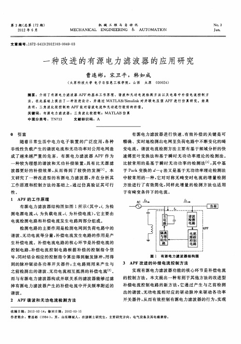
附录附录一:英文文献A 10KV Shunt Hybrid Active Filter for a PowerDistributionSystemAbstract—this paper analyzes the compensation performance of a shunt hybrid active power filter. The hybrid active power filter, which combines passive filter and active power filter, has both respective merits, and is an important developing trend of filtering device. The hybrid active power filter can reduce the capacity of active power filter effectively and is more suitable for the engineering application for high voltage nonlinear loads. The compensation performance of hybrid active power filter is analyzed by estimating the effect of different active power filter gain and parameters change. Then, a conclusion has been obtained that the harmonic attenuation rate is insensitive to the variation of passive parameters when the active power filter with an enough feedback gain is combined. Finally, the feasibility and validity of proposed scheme is verified by Simulation using Matlab and a hybrid shunt active power filter prototype.Index Terms:Current harmonics compensation, active power filter, passive filter, generalized integrators.I .INTRODUCTIONIn the development of power electronics brings convenience to energy conversion and utilization and also causes power quality problems. As one of the key technologies in combating power grid pollution and improving the power quality, active power filter (APF) has become a new research emphasis in power electronics technology[1]-[5].Because of high initial cost, the further application of active power filter is restricted. The HAPF(Hybrid Active Power Filter), combination of APF and passive filter (PF), can reduce the capacity of Affectively and is more suitable for the engineering application of APF for high voltage nonlinear loads.Traditionally, Passive filter has been used to eliminate the harmonic in power system due to his low cost and high efficiency. A passive filter shows the low impedance at tuned frequency to absorb current harmonic and has a good compensation performance. However, passive filter has the disadvantage of depending on the parameters of power system, susceptible to the load and power system resonant and the characteristic change due to aging. In addition, passive filter usually is designed with fixed parameters, which can not be lightly adapted for the variation operation condition.Active power filter has been developed to overcome of disadvantages of passive filter and can provide flexible and reliable compensation, but is not a cost-effective solution duet the high operation cost.Because of the drawbacks of passive filter and active power filter, the research on hybrid active power filter has become more attractive [6]-[9]. Hybrid active power filter composed of passive filter connected in series to an active power filter improves the compensation performance ofpassive filter remarkably, give more flexibility and reliability to filter device, and redound to the use of active power filter in high-power system avoiding the expensive initial cost.In this paper, the compensation performance of hybrid active power filter in an industrial power distribution system is analyzed by estimating the effect of different active power filter gain and parameters change. Finally, the compensation of hybrid active power filter is verified by simulation and a laboratory prototype. The passive filter of prototype was tuned at the seventh harmonic and the generalized integrators are used to eliminate the 5th, 11th and 13th harmonic current[10].II. PRINCIPLES OF CURRENT HARMONIC COMPENSATION The hybrid active power filter topology is shown in Fig.1, which consists of a three-phase pulse width modulation(PWM) voltage-source inverter (active power filter, APF)and the passive filter connected in series to APF through coupling transformer. Generally, the active power filter acts as a controlled voltage source and force the harmonic current into the hybrid active power filter. The principle of operation of current harmonic is explained by the single-phase equivalent circuit shown in Fig.2 when the feedback control is applied to the active power filter. In the current harmonic compensation strategy, the active power filter is considered as a controlled voltage source VAPF, and ZF is the impedance of passive filter, ILh is the load harmonic current, ZS is the systemimpedance.In order to eliminate harmonic of the system current, the active power filter is controlled as a current controlled voltage source. The active power filter imposes a voltage signal V APF that forces load harmonic current flow into the passive filter, thus improving its compensation performance in despite of the variation in the tuned frequency of the passive filter. The voltage reference of active power filter is equal toVAPF = K ⋅I sh (1) Where, K is the harmonic compensation gain. Supposing utility voltage is pure sinusoidal, the ration between the utility harmonic current and the load harmonic current is obtained, which can be used to denote the filtering characteristics of hybrid active power filter.Otherwise, K acts as a resistance to damp resonance between ZS and ZF. The larger K is selected, the lower the harmonic contents in the utility current. But this will increase the required power rating of the active power filter. In real condition, K is finite. Otherwise, closed loop control system will become unstable.Fig. 1 hybrid active power filter configuration.Fig. 2 Single-phase equivalent circuit of the hybrid active power filter scheme.III. ANALYSIS OF THE HYBRID FILTERPERFORMANCE IN ADISTRIBUTION SYSTEMThis section will show the compensation performance of hybrid active power filter through an example. The power distribution energizes the six medium frequency furnace, each of 300KW rate power. The medium frequency furnaces energized by six pulse uncontrolled rectifiers. The single phase diagram of the power distribution is shown in Fig.3only considering hybrid active power filter and medium frequency furnace.Fig. 3 Single-phase line diagram of the power distribution systemThe system harmonic content and harmonic criterion are shown in Table I and the 5th, 7th and 11th frequency harmonics exceed the criterion. So, the passive filters are tuned at the 5th, 7th and 11thfrequency harmonic and the rate of reactive power compensation is 500kVar. The system inductance and the parameters of passive filters are shown in Table II.TABLE IPOWER SYSTEM AND PASSIVE FILTER PAREMETERSTABLE IIPOWER SYSTEM AND PASSIVE FILTER PAREMETERSIn this case, the rate of active power filter is 25KVA since it would only compensate current harmonic and the coupling transformers turns ratio is equal to 2.Fig.4 (a) shows the harmonic attenuation rate of passive filter and hybrid active power filter. The hybrid active power filter is characterized by using three single resonant filter tuned at the 5th, 7th and 11th harmonic frequency as shown inFig.3. Therefore, the passive filter presents low impedance at the 5th, 7th and 11th harmonic frequency and their neighborhood. When no active power filter is connected in series with the passive filter, the harmonic amplifying phenomenon appear in the frequency range of 200-240Hz,300-340Hz and 500-640Hz. When the active power filter with a feedback gain of 20 is combined, no harmonic amplifying phenomena occurs. Meanwhile, only adapting the passive filter, the filtering characteristic is unsatisfactory even at the 5th, 7th and 11th harmonic frequency. When the active power filter with a feedback gain of 20 is combined, the harmonic attenuation rate isincreased and the filter performance of the hybrid active power filter is satisfactory at the 5th, 7th and 11th harmonic frequency.Fig.4 (b) shows the harmonic content of power system indifferent condition. When no filter is connected in parallel with the utility, the 5th, 7th and 11th harmonic current exceed the criterion seriously. After only adapting the passive filter, the harmonic current of utility is weakened but unsatisfactory adequately. When the active power filter with a feedback gain of 20 is combined, most of 5th, 7th and 11th harmonic current is forced flowing into the hybrid active power filter.Fig.5 shows how the active power filter gain K changes the harmonic attenuation rate of system current. Large value of K improves the hybrid active power filter compensation performance by increase the harmonic impedance of power system.In addition, Fig.5 shows that the low values of passive filter quality factor Q will increases the impedance at the resonant frequency and weaken the compensation performance of hybrid active power filter. The passive filter quality factor Q decides the passive filter bandwidth. Though increasing the value of active power filter gain K can compensate the adverse effect of low value of Q, which would results in the increase of active power filter output voltage required to keep the same compensation performance, thus increasing the active power filter rated power.Fig. 4 Hybrid active power filter frequency response and Harmonic Content.From Fig.5, a conclusion can be received that the quality factor of passive filter and the active power filter gain directly affect the compensation performance of hybrid active power filter when the tuned frequency is fixed. If the quality factor of passive filter is not properly selected, the active power filter gain K must been increased to obtain the satisfying compensation performance.Fig. 5 Hybrid active power filter frequency response for different values of passive filter qualityfactor Q.Fig.6 shows the hybrid active filter frequency response for different values of the system equivalent impedance. Generally, the system equivalent impedance must be lower to the passive filter equivalent impedance at the resonant frequency; otherwise, the passive can not obtain the favorable compensation performance and most load harmonic current will flow to the power system. When no active powerfilter is connected in series with the passive filter, if utility impedance is lower than the passive filter impedance at the tuned frequency, the harmonic attenuation rate is decreased and the filter performance of passive filter is unsatisfactory, as shown in Fig.6 (a). When the active power filter with an enough feedback gain is combined, the harmonic attenuation rate is insensitive to the variation of utility impedance, as shown in Fig.6 (b).Fig.6 also depicts that the active power filter gain K in bulky utility (small values of Zs) must bigger than that in weak utility (big value of Zs) to obtain the same compensation performance.Fig. 6 Hybrid active power filter frequency response for different values of the system equivalentimpedance.The simulation results are shown in Fig.7-10. Fig.7 shows the phase-a load current and it can be seen that the load current is greatly distorted. Fig.8 presents the phase-a supply current when hybrid active power filter is working. Now it can be seen that the hybrid active power filter has improved the quality of supply current markedly and the dominating harmonic current has been eliminated effectively. Fig.9 shows the phase-a hybrid filter current. It consists of 5th, 7thand 11th harmonic current mostly.The dynamic compensation performance is studied by load perturbation response and shown in Fig.10. The change in the source current is observed smooth and steady state is reached within 2 cycles.Fig.7. Simulated current waveforms for hybrid filter compensation. Top: simulate load current;bottom: its frequency spectrumFig.8. Simulated current waveforms for hybrid filter compensation. Top: simulate system linecurrent; bottom: its frequency spectrum.Fig.9. Simulated current waveforms for hybrid filter compensation. Top: simulate hybrid filtercurrent; bottom: its frequency spectrum.Fig.10. Dynamic simulated current waveforms for hybrid filter compensation. Top: simulate system line current; middle: simulate load current; bottom: simulate hybrid filter current.IV. EXPERIMENTAL RESULTSA three-phase hybrid shunt active power filter laboratory prototype using IGBT was implemented and tested in the compensation of a six-pulse uncontrolled rectifier, as shown in Fig.11. The VSI dc-link voltage is composed of a capacitor bank of 6800μF for a dc-link voltage 450V. The Eupec 1200V/200A IGBT are used and driven by theM57962L gate drivers. The digital control system incorporates a double DSP (TMS320C32 and TMS320F240) and CPLD circuit. The sampling period is 200 μs . Phase detection and control algorithm are completed byTMS320C32, and sampling and SVPWM program are implemented by TMS320F240. The inverter was operated at5-kHz switching frequency and was connected in series to a passive filter directly. The passive filter was tuned at the seventh harmonic (350Hz) and quality factor Q equal to 60.The parameters of the experiment circuit are shown in Table III.Fig.11 PI current controller using generalized integratorsTABLE IIITHE PARAMETERS OF THE EXPERIMENT CIRCUITSince such a single seventh harmonic tuned LC filter issued, a no negligible amount of the 5th, 11th and 13thharmonic current still remains in the supply. Thus, the generalized integrators are used to eliminate the 5th, 11th and13th harmonic current.The proposed controller based on generalized integrators in stationary frame is depicted in Fig.12, Where, *VAPF is Violate reference , *is is grid current reference.Fig.12 PI current controller using generalized integratorsWhere, Ki is the integral coefficient. The following discrete formula is use to realize the digital generalized integrators.For reducing the computation time, the generalized integrators are implemented by iterative arithmetic.When generalized integrators are used, the harmonic attenuation rate is shown in Fig.13. Fig.13 illustrates that the5th, 11th, 13th, 17th and 19th harmonic current are eliminated effectively by reason of generalized integrators.Steady-state experimental results are shown in Figs.14-16.Fig.14 (a) shows the experimental waveform of load current; the associate frequency spectrum is shown in Fig.14 (b).In this case, the load current consists of a mass of harmonic current. As shown in Fig.15, when only proportion controller is used, the elimination of harmonics besides tuned frequency is very limited by hybrid active power filter.With hybrid active power filter compensation using PI controller based on generalized integrators, the 5th, 7th, 11th,13th, 17thand 19th harmonics had been eliminated effectively as shown in Fig.16. When the shunt APF is plunged, the DC linkvoltage can arrive at reference value rapidly, as shown in Fig 7...Fig.14. Experimental load current waveforms. (a) Load current. (b) Load current frequencyspectrum.Fig.16. Experimental system current waveforms with hybrid filter compensation. (a) Systemcurrent. (b) System current frequency spectrum.Fig.17. Experimental system current waveforms with hybrid filter compensation.V. CONCLUSIONThe compensation performance of a shunt hybrid active power filter is proposed and analyzed. The hybrid active power filter, which combines passive filter and active power filter, has both respective merits, and is an important developing trend of filtering device. The hybrid active power filter can reduce the capacity of active power filter effectively and is more suitable for the engineering application for high voltage nonlinear loads. The compensation performance of hybrid active power filter is analyzed for different active power filter gain and parameters change. Above all, an conclusion can be obtained that the harmonic attenuation rate is insensitive to the variation of passive parameters when the active powerfilter with an enough feedback gain is combined. The feasibility and validity of proposed scheme is verified by Simulation using Matlab and a hybrid shunt active power filter prototype.附录二:中文翻译与10kV配电系统并联的混合型有源电力滤波器摘要本文分析了并联混合型有源电力滤波器的补偿性能。
一种改进的有源电力滤波器的应用研究
[ ] 陈保 . 联 有 源 电力 滤 波器 实 用 关 键 技 术 研 究 [ . 州 : 4 并 D] 杭
浙 江大 学 ,0 9 2—2 2 0 :93 .
[] 庞浩 , 5 王暂 基 , 建 业 . 联 型 直 流 有 源 电 力 滤 波 器 的控 陈 并
0 1H, . 电容 C一( . ×1 )F。电流 仿 真 波形 如 图 10 0 5 示 。从 仿 真 结果 可 以 看 出 , 角 波 比较 控 制 方 法 所 三 控制 的有源 电力 滤波器能 够实现 较快 的动 态响应 速度
制方 法 , 整个 AP F系统 仿真算 法采用 o e 5 d4 。
・
5 ・ O
机 械 工 程 与 自 动 化
21 0 2年 第 3期
对 谐波 电 流 的有 效 实 时补 偿[ 。 目前 , 常 用 的控 制 4 ] 较
方法有 三 角波 比较控 制 、 环 比较 控制 等 。 滞 三角 波 比较法是 目前应 用 较为广 泛 的一 种线 性 电
波时, 此种 方法 增大 了数字化 控制 器 的难度 。 ]
wa i ltd b ATLAB/ i l k Th e ut h w h tAPF c n r l db ra ge p lec mp rs n meh d c n c mp n ae ssmuae y M S mui . n ers lss o ta o tol ytin l us o aio to a o e s t e
滤 波器 系统对 负载 中的谐 波和无 功 电流进行 了有效 的
( )补偿 前 电流 8
补偿 。随着数字 信号 处理器 技 术 的发展 , D P实 现 用 S 对 AP F的控制 是一 种很 有发展 潜力 的控制 方法 。
有源滤波技术综述
(上接第323页)摘要:有源滤波器是近几年兴起的电力电子装置,它能够有效的抑制谐波,提高供电质量。
该文首先阐明了有源滤波器的工作原理和连接方式,详细分析了有源滤波器常用的控制策略,最后结合近几年的研究现状总结了有源滤波技术的发展趋势。
关键词:有源滤波谐波控制策略综述0引言随着电力电子装置应用的增多,越来越多的非线性负载被接入电力系统中,电能质量因此也受到了严重污染。
同时,现代精密工业和商业用户的用电设备对电能质量的要求也更加严格。
因此,需要一种更为有效的方法滤除电力谐波,提高电能质量。
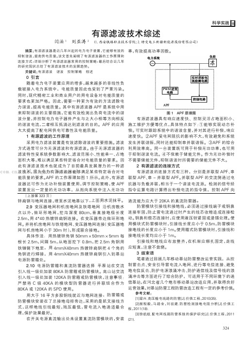
其中有源滤波器APF 是系统中用来抑制谐波的主要措施,它能有效检测出负荷电流中的谐波分量,并控制电力电子器件产生与之大小相等方向相反的谐波电流,二者相互抵消达到滤波的目的。
APF 的应用大大提高了配电网供电可靠性及电能质量。
1有源滤波的工作原理采用电力滤波装置是有效滤除谐波的重要措施。
滤波方式通常可分为无源滤波和有源滤波。
由于无源滤波器的滤波特性受系统参数影响大、滤波范围小、性能单一、占地面积大等,难以满足某些特定场合对电能质量的要求。
因此有源滤波技术也就成为了目前最具发展潜力的一种滤波技术,因为电力有源滤波器能够满足某些特定场合对电能质量的要求。
APF 的工作原理如图1所示。
此外,有源滤波器还可作为无功补偿装置使用,调节控制策略,使APF 装置发出一定量的无功功率,从而向系统中注入无功功率,有效提高功率因数。
图1APF 原理图有源滤波器具有响应速度快、控制灵活占地面积小、施工维护方便等优点,具体特点如下:①能够实现动态补偿。
可实时跟踪系统中的谐波含量,并对其进行补偿,响应速度快。
②APF 受电网阻抗的影响不大,有效避免和系统发生并联谐振,同时还能抑制串并联谐振。
③APF 的综合利用效率高。
同一台装置既可用于补偿无功功率,也可用于抑制谐波电流。
④不依赖于储能元件。
作为无功补偿时不需要储能元件,抑制谐波时所需要的储能元件不大。
有源电力滤波器英文文献和中文翻译

附录附录一:英文文献A 10KV Shunt Hybrid Active Filter for a Power DistributionSystemAbstract—this paper analyzes the compensation performance of a shunt hybrid active power filter. The hybrid active power filter, which combines passive filter and active power filter, has both respective merits, and is an important developing trend of filtering device. The hybrid active power filter can reduce the capacity of active power filter effectively and is more suitable for the engineering application for high voltage nonlinear loads. The compensation performance of hybrid active power filter is analyzed by estimating the effect of different active power filter gain and parameters change. Then, a conclusion has been obtained that the harmonic attenuation rate is insensitive to the variation of passive parameters when the active power filter with an enough feedback gain is combined. Finally, the feasibility and validity of proposed scheme is verified by Simulation using Matlab and a hybrid shunt active power filter prototype.Index Terms:Current harmonics compensation, active power filter, passive filter, generalized integrators.I .INTRODUCTIONIn the development of power electronics brings convenience to energy conversion and utilization and also causes power quality problems. As one of the key technologies in combating power grid pollution and improving the power quality, active power filter (APF) has become a new research emphasis in power electronics technology[1]-[5]. Because of high initial cost, the further application of active power filter is restricted. The HAPF(Hybrid Active Power Filter), combination of APF and passive filter (PF), can reduce the capacity of Affectively and is more suitable for the engineering application of APF for high voltage nonlinear loads.Traditionally, Passive filter has been used to eliminate the harmonic in power system due to his low cost and high efficiency. A passive filter shows the low impedance at tuned frequency to absorb current harmonic and has a good compensation performance. However, passive filter has the disadvantage of depending on the parameters of power system, susceptible to the load and power system resonant and the characteristic change due to aging. In addition, passive filter usually is designed with fixed parameters, which can not be lightly adapted for the variation operation condition.Active power filter has been developed to overcome of disadvantages of passive filter and can provide flexible and reliable compensation, but is not a cost-effective solution duet the high operation cost.Because of the drawbacks of passive filter and active power filter, the research on hybrid active power filter has become more attractive [6]-[9]. Hybrid active power filter composed of passive filter connected in series to an active power filter improves the compensation performance of passive filter remarkably, give more flexibility and reliability to filter device, and redound to the use of active power filter in high-power system avoiding the expensive initial cost.In this paper, the compensation performance of hybrid active power filter in an industrial power distribution system is analyzed by estimating the effect of different active power filter gain and parameters change. Finally, the compensation of hybrid active power filter is verified by simulation and a laboratory prototype. The passive filter of prototype was tuned at the seventh harmonic and the generalized integrators are used to eliminate the 5th, 11th and 13th harmonic current[10].II. PRINCIPLES OF CURRENT HARMONIC COMPENSATION The hybrid active power filter topology is shown in Fig.1, which consists of a three-phase pulse width modulation(PWM) voltage-source inverter (active power filter, APF)and the passive filter connected in series to APF through coupling transformer. Generally, the active power filter acts as a controlled voltage source and force the harmonic current into the hybrid active power filter. The principle of operation of current harmonic is explained by the single-phase equivalent circuit shown in Fig.2 when the feedback control is applied to the active power filter. In the current harmonic compensation strategy, the active power filter is considered as a controlled voltage source VAPF, and ZF is the impedance of passive filter, ILh is the load harmonic current, ZS is the system impedance.In order to eliminate harmonic of the system current, the active power filter is controlled as a current controlled voltage source. The active power filter imposes a voltage signal V APF that forces load harmonic current flow into the passive filter, thus improving its compensation performance in despite of the variation in the tuned frequency of the passive filter. The voltage reference of active power filter is equal toVAPF = K ⋅I sh (1) Where, K is the harmonic compensation gain. Supposing utility voltage is pure sinusoidal, the ration between the utility harmonic current and the load harmonic current is obtained, which can be used to denote the filtering characteristics of hybrid active power filter.Otherwise, K acts as a resistance to damp resonance between ZS and ZF. The larger K is selected, the lower the harmonic contents in the utility current. But thiswill increase the required power rating of the active power filter. In real condition, K is finite. Otherwise, closed loop control system will become unstable.Fig. 1 hybrid active power filter configuration.Fig. 2 Single-phase equivalent circuit of the hybrid active power filter scheme.III. ANALYSIS OF THE HYBRID FILTERPERFORMANCE IN ADISTRIBUTION SYSTEMThis section will show the compensation performance of hybrid active power filter through an example. The power distribution energizes the six medium frequency furnace, each of 300KW rate power. The medium frequency furnaces energized by six pulse uncontrolled rectifiers. The single phase diagram of the power distribution is shown in Fig.3only considering hybrid active power filter and medium frequency furnace.Fig. 3 Single-phase line diagram of the power distribution systemThe system harmonic content and harmonic criterion are shown in Table I and the 5th, 7th and 11th frequency harmonics exceed the criterion. So, the passive filters are tuned at the 5th, 7th and 11th frequency harmonic and the rate of reactive power compensation is 500kVar. The system inductance and the parameters of passive filters are shown in Table II.TABLE IIn this case, the rate of active power filter is 25KVA since it would only compensate current harmonic and the coupling transformers turns ratio is equal to 2.Fig.4 (a) shows the harmonic attenuation rate of passive filter and hybrid active power filter. The hybrid active power filter is characterized by using three single resonant filter tuned at the 5th, 7th and 11th harmonic frequency as shown inFig.3. Therefore, the passive filter presents low impedance at the 5th, 7th and 11th harmonic frequency and their neighborhood. When no active power filter is connected in series with the passive filter, the harmonic amplifying phenomenon appear in the frequency range of 200-240Hz,300-340Hz and 500-640Hz. When the active power filter with a feedback gain of 20 is combined, no harmonic amplifying phenomena occurs. Meanwhile, only adapting the passive filter, the filtering characteristic is unsatisfactory even at the 5th, 7th and 11th harmonic frequency. When the active power filter with a feedback gain of 20 is combined, the harmonic attenuation rate is increased and the filter performance of the hybrid active power filter is satisfactory at the 5th, 7th and 11th harmonic frequency.Fig.4 (b) shows the harmonic content of power system indifferent condition. When no filter is connected in parallel with the utility, the 5th, 7th and 11th harmonic current exceed the criterion seriously. After only adapting the passive filter, the harmonic current of utility is weakened but unsatisfactory adequately. When the active power filter with a feedback gain of 20 is combined, most of 5th, 7th and 11th harmonic current is forced flowing into the hybrid active power filter.Fig.5 shows how the active power filter gain K changes the harmonic attenuation rate of system current. Large value of K improves the hybrid active power filter compensation performance by increase the harmonic impedance of power system.In addition, Fig.5 shows that the low values of passive filter quality factor Q will increases the impedance at the resonant frequency and weaken the compensation performance of hybrid active power filter. The passive filter quality factor Q decides the passive filter bandwidth. Though increasing the value of active power filter gain K can compensate the adverse effect of low value of Q, which would results in the increase of active power filter output voltage required to keep the same compensation performance, thus increasing the active power filter rated power.Fig. 4 Hybrid active power filter frequency response and Harmonic Content.From Fig.5, a conclusion can be received that the quality factor of passive filter and the active power filter gain directly affect the compensation performance of hybrid active power filter when the tuned frequency is fixed. If the quality factor of passive filter is not properly selected, the active power filter gain K must beenincreased to obtain the satisfying compensation performance.Fig. 5 Hybrid active power filter frequency response for different values of passive filter quality factor Q.Fig.6 shows the hybrid active filter frequency response for different values of the system equivalent impedance. Generally, the system equivalent impedance must be lower to the passive filter equivalent impedance at the resonant frequency; otherwise, the passive can not obtain the favorable compensation performance and most load harmonic current will flow to the power system. When no active power filter is connected in series with the passive filter, if utility impedance is lower than the passive filter impedance at the tuned frequency, the harmonic attenuation rate is decreased and the filter performance of passive filter is unsatisfactory, as shown in Fig.6 (a). When the active power filter with an enough feedback gain is combined, the harmonic attenuation rate is insensitive to the variation of utility impedance, as shown in Fig.6 (b).Fig.6 also depicts that the active power filter gain K in bulky utility (small values of Zs) must bigger than that in weak utility (big value of Zs) to obtain the same compensation performance.Fig. 6 Hybrid active power filter frequency response for different values of the system equivalent impedance.The simulation results are shown in Fig.7-10. Fig.7 shows the phase-a load current and it can be seen that the load current is greatly distorted. Fig.8 presents the phase-a supply current when hybrid active power filter is working. Now it can be seen that the hybrid active power filter has improved the quality of supply current markedly and the dominating harmonic current has been eliminated effectively. Fig.9 shows the phase-a hybrid filter current. It consists of 5th, 7thand 11th harmonic current mostly.The dynamic compensation performance is studied by load perturbation response and shown in Fig.10. The change in the source current is observed smooth and steady state is reached within 2 cycles.Fig.7. Simulated current waveforms for hybrid filter compensation. Top: simulate load current; bottom: itsfrequency spectrumFig.8. Simulated current waveforms for hybrid filter compensation. Top: simulate system line current; bottom: itsfrequency spectrum.Fig.9. Simulated current waveforms for hybrid filter compensation. Top: simulate hybrid filter current; bottom: itsfrequency spectrum.Fig.10. Dynamic simulated current waveforms for hybrid filter compensation. Top: simulate system line current;middle: simulate load current; bottom: simulate hybrid filter current.IV. EXPERIMENTAL RESULTSA three-phase hybrid shunt active power filter laboratory prototype using IGBTwas implemented and tested in the compensation of a six-pulse uncontrolled rectifier, as shown in Fig.11. The VSI dc-link voltage is composed of a capacitor bank of 6800μF for a dc-link voltage 450V. The Eupec 1200V/200A IGBT are used and driven by theM57962L gate drivers. The digital control system incorporates a double DSP (TMS320C32 and TMS320F240) and CPLD circuit. The sampling period is 200 μs . Phase detection and control algorithm are completed byTMS320C32, and sampling and SVPWM program are implemented by TMS320F240. The inverter was operated at5-kHz switching frequency and was connected in series to a passive filter directly. The passive filter was tuned at the seventh harmonic (350Hz) and quality factor Q equal to 60.The parameters of the experiment circuit are shown in Table III.Fig.11 PI current controller using generalized integratorsTABLE IIISince such a single seventh harmonic tuned LC filter issued, a no negligible amount of the 5th, 11th and 13thharmonic current still remains in the supply. Thus, the generalized integrators are used to eliminate the 5th, 11th and13th harmonic current.The proposed controller based on generalized integrators in stationary frame is depicted in Fig.12, Where, *VAPF is Violate reference,*is is grid current reference.Fig.12 PI current controller using generalized integratorsWhere, Ki is the integral coefficient. The following discrete formula is use to realize the digital generalized integrators.For reducing the computation time, the generalized integrators are implemented by iterative arithmetic.When generalized integrators are used, the harmonic attenuation rate is shown in Fig.13. Fig.13 illustrates that the5th, 11th, 13th, 17th and 19th harmonic current are eliminated effectively by reason of generalized integrators.In this case, the load current consists of a mass of harmonic current. As shown in Fig.15, when only proportion controller is used, the elimination of harmonics besides tuned frequency is very limited by hybrid active power filter.With hybrid active power filter compensation using PI controller based on generalized integrators, the 5th, 7th, 11th,13th, 17thand 19th harmonics had beeneliminated effectively as shown in Fig.16. When the shunt APF is plunged, the DC linkvoltage can arrive at reference value rapidly, as shown in Fig 7...Fig.14. Experimental load current waveforms. (a) Load current. (b) Load current frequency spectrum. Fig.16. Experimental system current waveforms with hybrid filter compensation. (a) System current. (b) Systemcurrent frequency spectrum.Fig.17. Experimental system current waveforms with hybrid filter compensation.V. CONCLUSIONThe compensation performance of a shunt hybrid active power filter is proposed and analyzed. The hybrid active power filter, which combines passive filter and active power filter, has both respective merits, and is an important developing trend of filtering device. The hybrid active power filter can reduce the capacity of active power filter effectively and is more suitable for the engineering application for high voltage nonlinear loads. The compensation performance of hybrid active power filter is analyzed for different active power filter gain and parameters change. Above all, an conclusion can be obtained that the harmonic attenuation rate is insensitive to the variation of passive parameters when the active power filter with an enough feedback gain is combined. The feasibility and validity of proposed scheme is verified by Simulation using Matlab and a hybrid shunt active power filter prototype.附录二:中文翻译与10kV配电系统并联的混合型有源电力滤波器摘要本文分析了并联混合型有源电力滤波器的补偿性能。
电力有源滤波器综述
文章编号:1004)289X(2004)05-0012-04电力有源滤波器综述李林静(浙江工业大学浙西分校信电系,浙江衢州324006)摘要:介绍了电力有源滤波器的工作原理和基本类型,阐述了电力有源滤波器的控制方法,对我国发展电力电子和有源滤波器技术提出几点看法。
关键词:补偿;电力有源滤波器;看法中图分类号:TM53文献标识码:BSum mary Of Active Po wer FilterLI Lin-jing(West B ranch,Zhejiang University of Technolo gy,Quzhou324006,China)Abstract:The operation principle and main type are presentde in the paper,and expound the contol method of the active power filter.Some perspectives on developing electric,electronic and active filter technologies are put forward f or our country.Key words:Compensation;active po wer filter;perspective1引言随着电力电子技术的飞速发展,越来越多的电力电子装置被广泛应用到各个领域,其中相当一部分负荷具有非线性或具有时变特性,造成了非线性、冲击性和不平衡用电特性,使电网中暂态冲击、无功功率、高次谐波及三相不平衡问题日趋严重,给公用电网的供电质量造成严重的污染,使电力系统的能量损耗增加,用电设备寿命缩短,对其它电子设备造成电磁干扰。
因此,解决电力系统谐波抑制及无功补偿,提高电网供电质量变得日益重要。
传统的谐波抑制和无功补偿的方法是电力无源滤波器与需补偿的非线性负载并联,为谐波提供一个低阻通路的同时也提供负载所需的无功功率。
有源电力滤波器毕业论文文献综述
文献综述随着计算机技术和网络技术的发展,工业参数的数字采集促进了现场总线技术的发展,目前现场总线已经从当初的4-20mA电流信号升级为数字信号,发展成为全数字通讯,解决了现场信号远距离高速传送的问题,而且提高了抗干扰性能,增加了系统配置的灵活性,节省了硬件投资,是未来生产自动化和过程控制的发展方向。
目前,较有影响的总线有:Modbus,CAN,LonWorks,Profibus等。
采用RS485标准总线技术对现场数据进行采集、管理,相对于CAN,LonWorks,Profibus等现场总线系统而言,具有结构简易、成本低廉、硬软件支持丰富、安装方便,且与传统的DCS兼容,与现场仪表接口简单,系统实施容易等特点,因而RS485总线系统在一定时间内仍是中小控制系统的主要形式。
温度测控模块作为一种重要的设备,在诸多工业生产过程中得到了广泛应用。
自70年代以来,由于工业过程控制的需要,特别是微电子技术和计算机技术的迅猛发展,国外温度测控发展迅速,并在智能化、自适应等方面取得显著成果。
在这方面,以口本、美国、德国、瑞典等国的技术领先,生产出了很多商品化的、性能优异的温度测控器及仪器仪表,并在各行业广泛应用。
目前,国外温度测控系统及仪表正朝着高精度、智能化、小型化等方面快速发展。
基于单片机的Modbus协议产品一般由单片机芯片为核心和外围辅助逻辑元器件组成,它充分利用单片机的硬件资源和软件资源,同时合理配置特定的功能元器件来实现产品的功用,外围元器件一部分是用来实现通讯的串行接口元件,具有电平转换的功能,这使得Modbus产品具有组成工业网络的能力;另一部分是功能器件,如:数模转化器、模数转化器、LED显示器等,能够实现很多的特定功能。
由于产品的硬件构成比较简单,性能比较稳定,功能比较强且造价比较低成为该产品的主要特点,在国内使用的Modbus产品大部分是国外产品,国内很少有独立的知识产权,这是Modbus产品在国内的现状。
有源电力滤波器综述
0引言近数十年以来很多国家都制定了限制谐波的规定和国家标准,电力谐波问题受到越来越多的关注,本着“谁污染,谁治理”的原则,随着中国绿色能源运动的不断深入,低压侧的谐波治理,必将提到日程上来。
而有源电力滤波器是一种用于动态抑制谐波和补偿无功的电力电子装置,被公认为是治理“电网污染”的有效手段,APF 有源滤波器作为一种主动型的谐波补偿装置,能动态跟踪补偿随机的谐波电流,克服传统LC 无源滤波装置的不足,具有高度的可控性和快速响应性,应用前景广阔[1-2]。
1有源滤波器的研究现状1971年日本的Machida 首先提出了有源滤波器的原始模型,同年,H.Sasaki 等就首次完整地描述了有源电力滤波器的基本原理[3],但由于当时是采用线性放大的方法产生补偿电流,其损耗大,成本高,因而仅在实验室研究,未能在工业中使用。
1976年,美国的Strycula 提出了用PWM 逆变器结构构成有源滤波器,确立了当今滤波器的基本结构,同年,L.Gyugyi 等人提出了用大功率晶体管PWM 逆变器构成的有源电力滤波器,并正式确立了有源滤波的概念,提出了有源滤波器主电路的基本拓扑结构和控制方法。
1982年,第1台采用GTO 作为开关元件的电流源PWM 逆变器构成的有源滤波器(800kVA)在日本研制成功并投入使用。
1983年,日本长冈科技大学的Akagi 等人基于pq 分解理论,提出了三相电路瞬时无功功率理论,为解决三相电力系统畸变电流的瞬时检测提供了理论依据。
表明实现有源滤波器补偿功能的条件已经具备,使有源电力补偿技术实用化研究得到了极大发展,与此同时,大功率晶体管(GTR)、大功率可关断晶闸管(GTO )、静电感应晶闸管(SITH )、静电感应晶体管(SIH )、功率场效应管(MOSFET )、场控晶闸管(MCT )及绝缘栅型双极性晶体管(IGBT )等新型快速大容量功率开关器件相继问世;PWM 调制技术、微机控制技术,以及数字信号处理技术都取得了长足的进步。
有源电力滤波器的研究综述

想要使项目建设成本控制达到真正的有效控制,就必须严格按照一定的经济责任制要求,贯彻实施责任和权利相匹配的原则类型,只有这样在项目建设过程中完全有效的确定各成本发生中心体系,它们都是有效控制成本的载体。
(四)营房建设项目管理成本控制的方法随着实践和科学研究的不断进行,到现在为止工程建设项目用来成本控制的基本方法和理论依据不断的增加,但是这些方法适合于不同的情况或者说是背景类型,在不同的建设背景下实施不同的控制方法将会产生不同的效果类型。
营房建设项目成本控制的基本方法类型包括以下几种:1.制度控制制度控制是从最基本的施工单位角度对项目成本实施过程中的总体进行宏观有效的控制。
它规定和约定了项目建设成本控制的有效方法和内容,用来解决项目施工建设过程中和成本控制管理中出现的可以有章可循、有例可根的重要问题的解决方法。
2.额度控制为了控制建设项目最终成本的核算结果,建设或者承包单位必须及时获取或者调查完整的市场材料等价格信息资料。
这些最基本的市场资料类型,对比以往历史资料按照一定比例予以控制和计算,由此用于确定建筑安装工程过程中材料基础定额。
3.合同控制为了有效的控制建设过程中的成本,除采取上述的办法用来控制成本外,还经常采取与以上方法相配套的合同控制的办法。
用合同来控制建设成本是指建设企业实施成本建设控制的重要方向之一。
合同管理与其他控制办法的最主要不同之处就在于前面的控制方法大多属于行政控制。
然而项目建设合同控制管理是指建设合作双方在合同自愿协商、自愿负责控制的基础上,产生的按照法律程式和方法具有约束力的有效控制办法。
作者简介:毕胜,1979年生,工作于中国人民解放军65139部队,现在长春工业大学攻读硕士研究生,项目管理专业。
摘要:随着电力电子技术的发展,电力电子装置在电力系统中的应用越来越广泛,应运而生的非线性和冲击性负载产生的谐波及无功电流对公共电网的污染也日渐严重。
在解决谐波问题的众多方法中,有源电力滤波器(APF)是一种相当具有发展前景的谐波抑制装置。
- 1、下载文档前请自行甄别文档内容的完整性,平台不提供额外的编辑、内容补充、找答案等附加服务。
- 2、"仅部分预览"的文档,不可在线预览部分如存在完整性等问题,可反馈申请退款(可完整预览的文档不适用该条件!)。
- 3、如文档侵犯您的权益,请联系客服反馈,我们会尽快为您处理(人工客服工作时间:9:00-18:30)。
重庆科技学院学生毕业设计(论文)文献综述题目有源电力滤波器技术院(系)电子信息学院专业班级自普本05学生姓名金涛学号2005441140 指导教师(签字)有源滤波技术文献综述摘要:随着各种功率器件的广泛应用,大量的谐波和无功电流注入电网,引起电网污染,造成电网电能质量问题日益严重但电力电子装置自身所具有的非线性也使得电网的电压和电流发生畸变。
过去,国内外大量采用无源滤波装置来进行谐波抑制和无功补偿,提高功率因数。
但无源滤波装置也存在着自身无法克服的不足和缺陷,有源电力滤波器由于具有高度可控性和快速响应性,能对频率和幅值都变化的谐波进行跟踪补偿,因而受到广泛的重视,成为目前国内外供电系统谐波抑制研究的热点。
关键词:有源电力滤波器逆变器1 引言随着电力电子技术的飞速发展,越来越多的电力电子装置被广泛应用到各个领域,近年来配电网中整流器、变频调速装置、电弧炉等非线性负荷不断增加,这些负荷的非线性、冲击性和不平衡的用特性,使电网中暂态冲击、无功功率、高次谐波及三相不平衡问题日趋严重,对公用电网的供电质量造成了严重影响,因此,消除电网中的谐波污染已成为电能质量研究中的一个重要课题。
有源电力滤波器(APF)是一种消除电网谐波的有效装置,具有高度可控和快速响应的特性,它不仅能补偿各次谐波,还可抑制闪变、补偿无功,有一机多能的特点。
其滤波特性不受系统阻抗的影响,同时还具有自我适应功能,可自动跟踪补偿变化的谐波。
有源滤波技术现状有源电力滤波器的基本工作原理是由HSasaki和HMachida于1971年首先提出的[1]。
他们首次提出了有源滤波器的原始结构模型,并建立了有源滤波器的基本理论。
他们提出的有源电力滤波器向电网注入一个与负载谐波电流幅值相等、相位相反的电流,从而抵消了电网中的谐波电流。
但由于当时是采用线性放大的方法产生小补偿电流,其损耗大,成本高,因而仅在实验室研究,未能在工业中实用。
1976年,LGyugyi和ECStyaula提出了用PWM逆变器构成的有源电力滤波器[2]。
这些采用PWM逆变器构成的有源电力滤波电路现已成为有源电力滤波器的基本结构。
20世纪80年代,随着电力电子技术和PWM控制技术的发展,对有源电力滤波器的研究逐渐活跃起来,成为电力电子技术领域的研究热点之一。
1983年赤木泰文等人提出的“三相电路瞬时无功功率理论”[3]极大的推动了有源电力滤波器的发展及其工程应用。
在国外,有源电力滤波器已开始在工业和民用设备上得到广泛使用,并且谐波补偿的次数逐步提高,有的可以高达25次谐波;单机装置的容量逐步提高。
如在日本和美国,应用领域可以接受的APF的容量已增加到50MVA,其应用领域从补偿用户自身的谐波向改善整个电力系统供电质量的方向发展。
我国在有源电力滤波器的应用研究方面,继日本、美国、德国等之后,得到学术界和企业界的充分重视,并投入了大量的人力和物力,到目前为止,国内对有源电力滤波器的研究基本上都局限于仿真研究和小型试验装置,工程实践应用仅仅也只是小功率的应用[4,5],而正式投入电网运行的几乎为零[6]总的来说,国内有源电力滤波器的应用技术和电子工业发达的国家相比有一定的差距。
最早的有源电力滤波器是单独使用的并联型有源电力滤波器,经过多年的发展,为了尽量发挥有源电力滤波器的特长,提高其性能并尽量降低其容量,结合无源电力滤波器的特点发展成了串联混合型有源电力滤波器、并联混合型有源电力滤波器等等,为了适应不同的补偿对象,发展了各种各样的有源滤波器形式。
根据有源滤波器和电网的连接方式,APF可以分为并联型和串联型两大类。
1986年Akagi H.提出了并联型APF单独使用方式[3],它是最早期的有源滤波装置。
图1.1 单独使用的并联型APF这种方式的主电路结构简单,但由于逆变器直接承受基波电压,所以其成本高且不适合高电压系统的补偿。
为降低成本、减小逆变器的容量和适应高电压的要求,人们利用PF 的成本低的优点,提出了各种APF与PF混合使用方式。
1987年Takeda M.等人提出用并联型APF和并联PF相结合的混合型APF[7]。
图1.2 并联型APF+并联PF的HAPF该方式利用无源部分滤除了大部分的谐波,所以其有源部分的谐波容量较小,且PF能够提供一定的无功功率,但逆变器仍然直接承受了基波电压,所以功率开关器件的耐压等级并没有降低。
1990年Fujita H.等人提出将APF与PF相串联后与电网并联的混合型方案[8]。
图1.3 APF与PF串联后并联接入电网的HAPF这种方式利用无源部分承受了大部分的基波电压,所以逆变器承受的基波电压小,适合于高电压系统的应用。
但由于流过无源部分的基波电流都流入逆变器,所以不能利用PF 提供大容量的无功功率。
利用无源元件LC的串、并联谐振特性,人们提出了注入式APF的结构[9,10]。
将LC对基波串联谐振电路作为有源部分的注入电路,能够大大降低APF承受的基波电压和容量,且可以利用无源元件提供无功功率,但其谐波容量相对较大,而且所能提供的无功容量有限。
随着电力电子技术的发展,全控型功率开关器件(如可关断晶闸管GTO和绝缘栅双极性晶体管IGBT)的电压和电流额定值不断提高,成本不断降低,人们从双或多逆变器的方向提出了各种APF的拓扑结构,来满足工业应用的要求。
1994年,Akagi H.等提出一种将串联型APF和并联型APF进行混合的方式,也称为统一电能质量调节器(Unified Power Quality Conditioner,UPQC)[11]。
图1.4 并联型APF+串联型APF的HAPF这种方式从理论上讲,可以抑制电压闪变、电压波动、不对称和谐波,但由于采用了双逆变器,所以存在控制复杂和成本高的缺点。
上述描述了并联型APF的发展现状,有源滤波器还有另外一大类——串联型APF,图1.5为典型的串连APF拓扑结构[12]。
图1.5 单独使用的串联型APF串联型APF单独使用方式能有效滤除电网的谐波电压,具有有源装置容量小和运行效率高等优点,但存在绝缘强度高、难以适应线路故障条件以及不能进行无功功率动态补偿等缺点,且负载的基波电流全都流过连接用的变压器,其工程实用性受到限制。
在串联型APF单独使用方式基础上发展出的串联型APF混合型结构[13,14],也都同样存在绝缘强度高和难以适应线路故障的缺点总结与展望本论文立足于有源电力滤波器的工业应用,对有源电力滤波器控制器的硬件模块构成、软件实现方法进行了详细的探讨当然,随着先进工业技术的发展,有源滤波器无论从设计上,还是从控制上都会不断得到提高,本文也只是有源电力滤波器技术研究的局部结合论文完成过程中遇到的困难以及实际工程实践中积累的经验,个人认为还有必要进行以下几方面的深入研究:(1)控制器的快速响应及装置的兼容性(2)降低有源滤波器的开关损耗(3)抑制有源滤波器的电磁干扰(4)进一步提高有源电力滤波器的可靠性参考文献[1]Sasaki H, Machida T. A New Method to Eliminate AC Harmonic Currents byMagnetic Compensation Consideration on Basic Design. IEEE Trans. on PAS, 1971, 90(5):2009-2019[2]Gyugyi L, Strycula E C. Active AC Power Filters. In: Proceedings ofIEEE/IAS Annual Meeting, 1976: 529-535[3]Akagi H,Kanazawa Y,Nabae A. Generalized theory of the instantaneousreactive power in three-phase circuits. In: IEEE & JIEE. Proceedingd IPEC.Tokyo: IEEE 1983.[4]陈国柱, 吕征宇, 钱照明. 50kVA变频调速器谐波的混合有源滤波. 电气传动, 2002年第3期:31~35[5]卓放, 杨君, 胡君飞, 王兆安. 30KVA并联型有源电力滤波器装置的研制.电工技术杂志, 2000.4:13~15[6]陶骏. HT-7U高功率电源系统无功功率补偿与谐波抑制的研究. 中科院等离子体物理所博士学位论文.[7]M. Takeda, K. Ikeda, and Y. Tominaga, Harmonic Current Compensation withan Active Filter, in Conf. Rec. of IEEE-IAS, 1987, pp. 808~815.[8]Fujita H, Akagi H. A Practical Approach to Harmonic Compensation in PowerSystems-Series Connection of Passive and Active Filters. In: IEEE IAS Annual Meeting Conference Record, 1990: 1107~1112[9]Atosuo N, Kiyoshi O. Active filter with series resonant circuit. IEEE PESC 88Record, APRIL 1988:1168~1175.[10]Noriaki T, Yoshiya O. Active Filter with Series LC Circuit. Proceedings ofIEEE ICHPS VI, Bologna, 1994[11]Akagi H, et al. A New Power Line Conditioner for Harmonic Compensation inPower Systems. IEEE Trans. on PWRD, 1995, 10 (3): 1570~1575[12]Peng F Z, Akagi H, Nabae A. A New Approach to Harmonic Compensation inPower System. In: IEEE IAS Conference Record, 1988. 874~880[13]Peng F Z, Akagi H, Nabae A. A New Approach to Harmonic Compensation inPower System-A Combined System of Shunt Passive and Series Active Filters.IEEE Trans. on IA, 1990, 26 (6): 983~990[14]Peng F Z, Lai J S. Application Considerations and CompensationCharacteristics of Shunt Active and Series Active Filters in Power Systems.Proceedings of IEEE ICHQP VII, Las Vegas, NV, 1996。