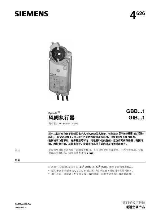
BELIMO风阀执行器
西门子 风阀执行器4626 说明书
GBB/GIB16..1 的控制信号 特性功能 GBB/GIB161.1, 166.1 GBB/GIB163.1, 164.1 GBB/GIB16...1的阀位指示器 GBB/GIB135.1, 335.1的 反馈电位计
GBB/GIB..4.1/..5.1/..6.1 的辅助开关 连接电线 壳体防护等级 保护等级 环境条件 标准和指令
弃置
西门子楼与科技 暖通空调产品
技术指标和环保声明文档提供关于此装置环境兼容性和弃置的信息。
GBB/GIB...1 角行程风阀执行器
3/4
CM2N4626Cn 2010.01.10
(Q12) (Q14) (Q22) (Q24) 4626G03
内部接线图 电线标签 尺寸
GBB/GIB13..1 / GBB/GIB33..1
配件、备件
可使用配件扩充执行器的功能,例如使用旋转 / 线性装置、辅助开关(1或2个开关)和 环境防护盖。请参见技术参数表N4699。
2/4
西门子楼宇科技 暖通空调产品
GBB/GIB...1 角行程风阀执行器
CM2N4626Cn 2010.01.10
技术参数
AC 24 V 电源 (SELV/PELV)
旋转方向 位置指示:机械 位置指示:电气 辅助开关 电源组 旋转角度限制
GBB.3..1 / GIB.3..1
GBB/GIB16..1
三位浮点
调节控制
DC 0...35 V,条件: 偏移 Uo = 0...5 V 和 范围 △U = 2...30 V
顺时针或逆时针方向取决于
...控制类型。未加电时,执行器保持在相应位 置。
(Y)
(G)
BELIMO风门执行器
BELIMO、BELIMO风门执行器、BELIMO电动蝶阀、BELIMO电动调节阀、BELIMO电动球阀、BELIMO蝶阀、BELIMO调节阀、BELIMO球阀瑞士BELIMO国内一级代理商上海蕴匠贸易有限公司常年低价供应瑞士BELIMO风门执行器、BELIMO电动蝶阀、BELIMO电动调节阀、BELIMO电动球阀、BELIMO蝶阀、BELIMO 调节阀、BELIMO球阀。
瑞士BELIMO公司始创于1975年6月1日,BELIMO已经从一家小型公司成长为现在的上市公司,不仅在** 各地设立了分公司及办公网点,并成为了全球暖通空调领域的领航者。
在过去的30年里,BELIMO的品牌,产品得到了众多客户及终端用户的一致认可;Belimo象征着优质的产品,快速的供货和永无止境的创新。
是全球最大actuator 阀门和技术供暖、通风、空调(暖气通风空调):齐全单一来源. 不论是空气或水电路、更安全的防火及排烟、空中管制室或个人提供最佳的解决方案。
瑞士BELIMO 风门执行器工作可靠,安装便捷。
测试快速,界面清晰,预置接线,为安全做好准备,与各知名厂商设备兼容;丰富的电气,机械配件,可安装于各种不同轴径的风门轴上,采用机械限位调整机械转角,宽范围有效扭矩可达30Nm,寿命长久,为暖通空调系统提供多种功能,久经考验的质量。
瑞士BELIMO风门执行器产品:风门执行器、电动蝶阀、电动调节阀、电动球阀等产品。
BELIMO 阀BU6100+GRVU230-5BELIMO 阀BU680+SRVU230-5BELIMO 电动蝶阀BU6125+GRVU230-7BELIMO 电动执行器BF24BELIMO 执行器SRVU24-5 20NM 24VAC/DCBELIMO 大液晶温控面板CFU-D222BELIMO 风阀执行器NMV-D3-MPBELIMO 电动二通阀DN20 Z220S-230BELIMO 大液晶温控面板CFU-D222BELIMO 阀BU665+SRVU230-5BELIMO 阀BU680+SRVU230-5BELIMO 阀BU6100+GRVU230-5BELIMO 阀BU6150+DGRVU230BELIMO 阀BU6200+SY3-230-3-TBELIMO 阀BU6250+SY4-230-3-TBELIMO 阀BU6300+SY4-230-3-TBELIMO 阀BU6350+SY6-230-3-TBELIMO 辅助开关S2ABELIMO 球阀R240BELIMO 球阀R223BELIMO 回转驱动装置SR24-MA UXO OTP SO9。
风阀执行器选型

1.34m2
由于交叉点落在LMU和NMU之间,所以选择NMU风门执行器
4
Together To The Top!来自5风阀执行器选型
典型风门的单位面积扭矩负载表
2
执行器选型计算
• 已知条件:
• • • • • • • • 平行叶片/无边缘密封 风门面积:1700mmX800mm 风量:20000m3/h 风门面积:1700mmX800mm=1.36m2 风速:20000/3600/1.36=4.08m/s 平行叶片/无边缘密封 迎面风速<5m/s 此时对应的单位面积扭矩负载为:5Nm/m2。
• 计算已知条件:
• 根据已知条件,查典型风门的单位面积扭矩负载表
• 风门需要的扭矩为:1.36X5=6.8Nm, • 考虑余量系数1.15,实际需要扭矩为:6.8X1.15=7.82Nm, 选择10Nm足够驱动1.36m2的风门。 • 所以可以选配BELIMO的NMU系列非弹簧复位风门执行器。
3
曲线图计算选型
SCHIEBEL电动执行器技术参数表说明书

TREIBENDE KRAFT FAILSAFE - ACTUSAFETechnical data sheet- PowerFlue gas treatmentHydro power plants Biomass power plants Nuclear power plants Boiler construction- Oil and GasReGas storagesTPower Plant Nueva CTE Habanaend user:Santa Cruz del NorteCubaSchiebel actuators in use:120 pcsCogeneration plant Salzburg RVL Lenzing - waste industryWORKING PRINCIPLEIn normal operation, the electromagnetic clutch is activated and couples the actuator and the failsafe unit. The movement of the actuator is transferred to the output of the failsafe unit, so the fi nal control element is oper-ated according to the position of the actuator.In case of power failure or releasing the ESD command via a cable or bus, the electromagnetic clutch opens and separates the self-locking actuator from the failsafe unit. Now the preloaded spring package is able to Ball screw spindle Spindle nutMultiturn actuatorDisc spring packageHydraulic damper DIMENSIONAL DRAWINGS WIRING DIAGRAMSStandard linear actuator controlled ACTUSAFE unit Assembling consoleControl Eddy current brakeDisc brake package switchSpindle nut Eddy current brakeBall screw spindleDisc brake package Parking brakeSpindle nuthand wheel engaged hand wheel disengagedIn normal operation, the electromagnetic clutch is activated and couples the actuator and the failsafe unit. The movement of the actuator is transferred to the output of the failsafe unit, so the fi nal control element is operated according to the position of the actuator.In case of power failure or releasing the ESD command via a cable or bus, the electromagnetic clutch opens and separates the self-locking actuator from the failsafe unit. Now the preloaded spring package is able to release, by moving the output unit with the fi nal control element into the failsafe position.The speed of this movement (failsafe speed) is limited by a maintenance free eddy current brake.The position of the fi nal control element is permanently monitored with the position sensing, so no start-up procedure is necessary for the failsafe unit to be re-armed.In case of activating the manual override a failsafe operation will be triggered by opening the electromagnetic clutch. After completion of the the move-ment, the fi nal control element can be moved in every position by the hand wheel.To deactivate the manual override the fi nal control element must be moved back into the failsafe position by the hand-wheel and the override must beMultiturn actuatorrackpinionDisc spring packageSpindle nutBall screw spindle Pinion reducer Eddy current brake Parking brakeThree phase AC motor DIMENSIONAL DRAWINGS WIRING DIAGRAMSSCHIEBELAntriebstechnik Ges.m.b.H.Josef-Benc-Gasse 41230 Vienna, AustriaT: +43 (0)1 66 108-0F: +43 (0)1 66 108-4*****************/actuators Niederlassungen / Branches : ■ Vertriebspartner / Sales partners:。
Belimo EV050R+KBAC-N 控制阀说明书

特性控制阀,具备带有自复位的传感器运行的流速或功率控制,以及功率和能量监测功能, 2 通, 内螺纹, PN 25 (能量阀)• 额定电压 AC/DC 24 V• 控制 调节型, 交互式, 混合模式型控制, 云• 用于闭合的冷、热水系统• 用于供热通风系统中水侧的调节控制• 以太网10/100 Mbit/s, TCP/IP, 内置网络服务器• 通过BACnet ,Modbus ,搏力谋MP-Bus 交互或采用常规控制• 可选择接入搏力谋云• 乙二醇监测型号概述型号DNRp ["]V'nom [l/s]V'nom [l/min]V'nom [m³/h]kvs theor. [m³/h]PN EV050R+KBAC-N502 6.337822.6832.025理论kvs: 理论 kvs 值用于压降计算技术数据电气参数额定电压AC/DC 24 V 额定频率50/60 Hz额定电压范围AC 19.2...28.8 V / DC 21.6...28.8 V 运行功耗15 W 保持功耗 6.5 W 变压器容量26 VA连接方式接线 1 m, 6 x 0.75 mm²以太网连接RJ45 插口并联运行是(注意功耗)数据总线通信通讯协议BACnet IP, BACnet MS/TP Modbus TCP, Modbus RTU MP-Bus 云节点数量BACnet / Modbus 详见接口描述MP-Bus 最多 8 个功能参数运行范围 Y 2...10 V 输入阻抗100 kΩ运行范围 Y 可调0.5...10 V 位置反馈信号U 2...10 V 位置反馈信号U 说明最大 1 mA 位置反馈信号U 可调0...10 V 0.5...10 V 电机噪音等级45 dB(A)可调节流量 V'max 30 ... 100%的Vnom控制精度±5% (V’nom 的25...100%)@20°C/ 不含乙二醇溶液控制精度注释±10% (V’nom 的25...100%)@-10...120°C/ 浓度为0...50%的乙二醇溶液最小可控流量V'nom 的 1%参数设置通过内置的网络服务器 / ZTH EU 介质冷、热水,最大浓度50%的乙二醇溶液介质温度-10...120°C介质温度说明流体温度在-10...2°C 范围内时,推荐使用阀轴加热器或阀脖延伸件。
Belimo EV..F+BAC 电子调节阀数据表说明书

EV..F+BACCharacterised control valve with sensor-operated flow rate or power control, power andenergy-monitoring function, 2-way, Flange, PN 16 (Energy Valve)• Nominal voltage AC/DC 24 V• Control modulating, communicative, hybrid, Cloud• For closed cold and warm water systems • For modulating control of air-handling and heating systems on the water side• Ethernet 10/100 Mbit/s, TCP/IP, integrated web server• Communication via BACnet, Modbus, Belimo MP-Bus or conventional control • optional Belimo Cloud connection • Glycol monitoringType OverviewType DN V'nom [l/s]V'nom [l/min]V'nom [m³/h]kvs theor. [m³/h]PN EV065F+BAC 65848028.85016EV080F+BAC 801166039.67516EV100F+BAC 1002012007212716EV125F+BAC 125311860111.619516EV150F+BAC15045270016225416kvs theor.: Theoretical kvs value for pressure drop calculationTechnical dataElectrical dataNominal voltageAC/DC 24 V Nominal voltage frequency 50/60 HzNominal voltage rangeAC 19.2...28.8 V / DC 21.6...28.8 V Power consumption in operation 7 W Power consumption in rest position 5 WPower consumption for wire sizing 6 VA (DN 65, 80)11 VA (DN 100, 125, 150)Connection supply / control Cable 1 m, 6x 0.75 mm²Connection Ethernet RJ45 socketParallel operationYes (note the performance data)Data bus communicationCommunicative controlBACnet/IP, BACnet MS/TP Modbus TCP, Modbus RTU MP-Bus CloudNumber of nodesBACnet / Modbus see interface description MP-Bus max. 8Functional data Operating range Y 2...10 V Input impedance100 kΩOperating range Y variable 0.5...10 V Position feedback U 2...10 V Position feedback U note Max. 1 mA Position feedback U variable 0...10 V 0.5...10 V Sound power level Motor45 dB(A)EV..F+BACFunctional data V'max adjustable30...100% of V'nomControl accuracy±5% (of 25...100% V'nom) @ 20°C / Glycol 0%vol.Control accuracy note±10% (of 25...100% V'nom) @ -10...120°C /Glycol 0...50% vol.Min. controllable flow1% of V'nomParametrisation via integrated web server / ZTH EUFluid Cold and warm water, water with glycol up tomax. 50% vol.Fluid temperature-10...120°C [14...248°F]Close-off pressure ∆ps690 kPaDifferential pressure Δpmax340kPaFlow characteristic equal percentage, optimised in the openingrange (switchable to linear)Leakage rate air-bubble tight, leakage rate A (EN 12266-1)Pipe connection Flangeaccording to EN 1092-2Installation orientation upright to horizontal (in relation to the stem)Servicing maintenance-freeManual override with push-button, can be locked Temperature measurement Measuring accuracy absolute temperature± 0.35°C @ 10°C (Pt1000 EN60751 Class B)± 0.6°C @ 60°C (Pt1000 EN60751 Class B)Measuring accuracy temperature difference±0.18 K @ ΔT = 10 K±0.23 K @ ΔT = 20 KResolution0.05°CFlow measurement Measuring principle Ultrasonic volumetric flow measurementMeasuring accuracy flow±2% (of 25...100% V'nom) @ 20°C / glycol 0%vol.Measuring accuracy flow note±6% (of 25...100% V'nom) @ -10...120°C /glycol 0...50% vol.Min. flow measurement0.5% of V'nomGlycol monitoring Measurement display glycol0...40% or >40%Measuring accuracy glycolmonitoring±4% (0...40%)Safety data Protection class IEC/EN III, Protective Extra-Low Voltage (PELV)Degree of protection IEC/EN IP40IP54 when using protective cap or protectivegrommet for RJ45 socketPressure equipment directive CE according to 2014/68/EUEMC CE according to 2014/30/EUType of action Type 1Rated impulse voltage supply / control0.8 kVPollution degree3Ambient humidity Max. 95% RH, non-condensingAmbient temperature-30...50°C [-22...122°F]Storage temperature-40...80°C [-40...176°F]Materials Valve body EN-GJL-250 (GG 25)Flow measuring pipe EN-GJL-250 (GG 25), with protective paintClosing element Stainless steel AISI 316EV..F+BACMaterialsSpindle Stainless steel AISI 304Spindle seal EPDMSeatPTFE, O-ring Viton Immersion sleeveStainless steel AISI 316Technical data••••Safety notesThis device has been designed for use in stationary heating, ventilation and air-conditioning systems and must not be used outside the specified field of application, especially in aircraft or in any other airborne means of transport.Outdoor application: only possible in case that no (sea) water, snow, ice, insolation or aggressive gases interfere directly with the device and that it is ensured that the ambient conditions remain within the thresholds according to the data sheet at any time.Only authorised specialists may carry out installation. All applicable legal or institutional installation regulations must be complied with during installation.The device contains electrical and electronic components and must not be disposed of as household refuse. All locally valid regulations and requirements must be observed.Product featuresOperating modeThe HVAC performance device is comprised of four components: characterised control valve (CCV), measuring pipe with flow sensor, temperature sensors and the actuator itself. The adjusted maximum flow (V'max) is assigned to the maximum control signal DDC (typically 10 V / 100%). Alternatively, the control signal DDC can be assigned to the valve opening angle or to the power required on the heat exchanger (see power control). The HVAC performance device can be controlled via communicative or analogue signals. The fluid is detected by the sensor in the measuring pipe and is applied as the flow value. The measured value is balanced with the setpoint. The actuator corrects the deviation by changing the valve position. The angle of rotation α varies according to the differential pressure through the control element (see flow curves).Flow rate curvesTransmission behaviour HE Heat exchanger transmission behaviourDepending on the construction, temperature spread, fluid characteristics and hydronic circuit,the power Q is not proportional to the water volumetric flow V' (Curve 1). With the classicaltype of temperature control, an attempt is made to maintain the control signal Y proportionalto the power Q (Curve 2). This is achieved by means of an equal-percentage flow characteristic(Curve 3).Power control Alternatively, the control signal DDC can be assigned to the output power required at the heat exchanger.Depending on the water temperature and air conditions, the Energy Valve ensures theamount of water V' required to achieve the desired power.Maximum controllable power on heat exchanger in power control mode:Control characteristics The specially configured control parameters in connection with the precise velocity sensorensure a stable quality of control. They are, however, not suitable for rapid control processes,i.e. for domestic water control.Power controlQ'nom is the maximum possible power output on the heat exchanger.Q'max is the maximum power output on the heat exchanger which has been set with thehighest control signal DDC. Q'max can be set between 1% and 100% of Q'nom.Q'min 0% (non-variable).Flow controlV'nom is the maximum possible flow.V'max is the maximum flow rate which has been set with the highest control signal. V'max canbe set between 30% and 100% of V'nom.Creep flow suppression Given the very low flow speed in the opening point, this can no longer be measured by the sensor within the required tolerance. This range is overridden electronically.Opening valveThe valve remains closed until the flow required by the control signal DDC corresponds to 1%of V'nom. The control along the flow characteristic is active after this value has beenexceeded.Closing valveThe control along the flow characteristic is active up to the required flow rate of 1% of V'nom.Once the level falls below this value, the flow rate is maintained at 1% of V'nom. If the levelfalls below the flow rate of 0.5% of V'nom required by the control signal DDC, then the valvewill close.Configurable actuators The factory settings cover the most common applications. Single parameters can be modified with the Belimo service tools MFT-P or ZTH EU.CommunicationThe parametrisation can be carried out through the integrated web server (RJ45 connection to the web browser) or by communicative means.Additional information regarding the integrated web server can be found in the separate documentation."Peer to Peer" connectionhttp://belimo.local:8080The Notebook must be set to "DHCP".Make sure that only one network connectionis active.Standard IP address:http://192.168.0.10:8080Static IP addressPassword (read-only):User name: «guest»Password: «guest»Control signal inversionThis can be inverted in cases of control with an analogue control signal DDC. The inversion causes the reversal of the standard behaviour, i.e. at a control signal DDC of 0%, regulation is to V'max or Q'max, and the valve is closed at a control signal DDC of 100%.Hydronic balancingVia the integrated web server, the maximum flow rate (equivalent to 100% requirement) can be adjusted on the device itself, simply and reliably, in a few steps. If the device is integrated in the management system, then the balancing can be handled directly by the management system.Delta-T managerIf a heating or cooling register is operated with a differential temperature that is too low and thus with a flow rate that is too high, this will not result in an increased power output.Nevertheless, heating or cooling machines must provide the energy at a lower degree of efficiency. This means, that pumps circulate too much water and increase energy consumption unnecessarily.With the aid of the Energy Valve, it is simple to discover that operation is being carried out at a differential temperature that is too low, resulting in the inefficient use of energy.Necessary setting adjustments can now be carried out quickly and easily at any time. The integrated differential temperature limiting offers the user the possibility of defining a low limit value. The Energy Valve limits the flow rate automatically to prevent the level from falling below this value.The settings of the Delta-T manager can be made either directly on the web server or via the Belimo Cloud a direct analysis of the Delta-T behavior is carried out by Belimo experts.Power output of the heating or coolingregisters 1Diff. temperature between supply and return2Loss zone (heating or cooling registersaturation) 3Adjustable minimum differential temperature4Combination analogue - communicative(hybrid mode)With conventional control by means of an analogue control signal DDC, the integrated web server, BACnet, Modbus or MP-Bus can be used for the communicative position feedback.EV..F+BACPower and energy monitoring functionThe HVAC performance device is equipped with two temperature sensors. One sensor (T2) is integrated in the measuring pipe, the second sensor (T1) is included with the system,prewired, and must be installed in the water circuit on site. The sensors are used to record the fluid temperature of the supply and return lines of the consumer (heating/cooling coil). As the water quantity is also known, thanks to the flow measurement integrated in the system, the power released from the consumer can be calculated. Furthermore, the heating/cooling energy is also determined automatically by means of the evaluation of the power over time.The current data, e.g. temperatures, volumetric flow volumes, exchanger energyconsumption etc. can be recorded and accessed at any time by means of web browsers or communication.Data recordingThe recorded data (integrated data recording for 13 months) can be used for the optimisation of the overall system and for the determination of the performance of the consumer (heating/cooling coil).Download csv files through web browser.Belimo CloudAdditional services are available if the Energy Valve is connected to the Belimo Cloud: forinstance, several devices may be managed via Internet. Also, Belimo experts may help analyse the delta-T behaviour or provide written reports about the Energy Valve performance. Under certain conditions, the product warranty according to the applicable Terms and Conditions of Sale may be prolonged. The "Terms of Use for Belimo Cloud Services" in their currently valid version apply to the use of Belimo Cloud services. Further details may be found under [/ext-warranty]Glycol monitoring Glycol monitoring measures the actual glycol content, which is necessary for safe operation and optimised heat exchange.Manual override Manual override with push-button possible (the gear train is disengaged for as long as the button is pressed or remains locked).High functional safetyThe actuator is overload protected, requires no limit switches and automatically stops when the end stop is reached.Product featuresAccessoriesElectrical accessoriesDescriptionType Grommet for RJ connection module, Multipack 50 pcs.Z-STRJ.1Stem heater flange F05 (30 W)ZR24-F05ToolsDescriptionTypeService tool, with ZIP-USB function, for parametrisable and communicative Belimo actuators, VAV controller and HVAC performance devicesZTH EU Connecting cable 5 m, A: RJ11 6/4 ZTH EU, B: 6-pin for connection to service socketZK1-GENElectrical installationSupply from isolating transformer.Parallel connection of other actuators possible. Observe the performance data.The wiring of the line for BACnet MS/TP / Modbus RTU is to be carried out in accordance with applicable RS-485 regulations.Modbus / BACnet: Supply and communication are not galvanically isolated. Connect earth signal of the devices with one another.EV..F+BACWire colours:1 = black 2 = red 3 = white 5 = orange 6 = pink 7 = greyFunctions:C1 = D- = A (wire 6)C2 = D+ = B (wire 7)Connection of a notebook for parametrisation and manual control via RJ45.Optional connection via RJ45 (direct connection Notebook / connection via Intranet or Internet) for access to the integrated web serverBACnet IP / Modbus TCPMP-Bus, supply via 3-wire connectionA) additional MP-Bus nodes (max. 8)MP-Bus via 2-wire connection, local power supplyA) additional MP-Bus nodes (max. 8)Electrical installationFunctionsFunctions when operated on MP-BusMP-Bus Network topologyThere are no restrictions for the network topology (star, ring, tree or mixed forms are permitted).Supply and communication in one and the same 3-wire cable • no shielding or twisting necessary• no terminating resistors requiredEV..F+BAC Functions with specific parameters (parametrisation necessary)BACnet MS/TP / Modbus RTU with analogue setpoint (hybrid mode)MP-Bus, supply via 3-wireconnectionMP-Bus with analog setpoint (hybrid mode)BACnet MS/TP / Modbus RTU with analog setpoint (hybrid mode)BACnet IP / Modbus TCP with analog setpoint (hybrid mode)MP-Bus via 2-wire connection, local power supplyMax. 8 additional MP-Bus nodesEV..F+BACFunctions with specific parameters (parametrisation necessary)Override control and limiting with DC 24 V with relay contacts (with conventional control or hybrid mode)1) Position control 2) Flow control 3) Power controlFunctionsOperating controls and indicators2LED display green Off:No power supply or wiring error On:In operationFlickering:Internal communication (Valve/Sensor)3Push-button and LED display yellow On:Adaptation or synchronisation process activePress button:Triggers angle of rotation adaptation, followed by standard mode4Manual override button Press button:Gear train disengages, motor stops, manual override possible Release button:Gear train engages, standard mode5Service plugFor connecting parametrisation and service toolsInstallation notesPermissible installation orientationThe ball valve can be installed upright to horizontal. The ball valve may not be installed in ahanging position, i.e. with the spindle pointing downwards.Installation location in return Installation in the return is recommended.Water quality requirementsThe water quality requirements specified in VDI 2035 must be adhered to.Belimo valves are regulating devices. For the valves to function correctly in the long term, they must be kept free from particle debris (e.g. welding beads during installation work). The installation of a suitable strainer is recommended.EV..F+BAC Spindle heater In cold water applications and warm humid ambient air, condensation can be caused in the actuators. This can lead to corrosion in the gear train of the actuator and a breakdown of theactuator. In such applications, the use of a spindle heater is recommended.The spindle heater must only be activated when the system is in operation because it does nothave a temperature controller.Servicing Ball valves, rotary actuators and sensors are maintenance-free.Before any service work on the control element is carried out, it is essential to isolate therotary actuator from the power supply (by unplugging the electrical cable if necessary). Anypumps in the part of the piping system concerned must also be switched off and theappropriate slide valves closed (allow all components to cool down first if necessary andalways reduce the system pressure to ambient pressure level).The system must not be returned to service until the ball valve and the rotary actuator havebeen correctly reassembled in accordance with the instructions and the pipeline has beenrefilled by professionally trained personnel.Flow direction The direction of flow, specified by an arrow on the housing, is to be complied with, since otherwise the flow rate will be measured incorrectly.Inlet section In order to achieve the specified measuring accuracy, a flow-calming section or inflow section in the direction of the flow is to be provided upstream from the flow sensor. Its dimensionsshould be at least 5x DN.EV..F+BACMounting of immersion sleeve andtemperature sensor The valve is equipped with two temperature sensors:• T2: One sensor is already installed in the valve unit.• T1: The second sensor must be mounted at the installation site ahead of the consumer (valvein the return line; recommended) or after the consumer (valve in the supply line). Theimmersion sleeve required is supplied with the valve unit.The temperature sensor is already wired with the valve.NoteThe cable between valve unit and temperature sensor may not be either shortened orlengthened.Split installation The valve-actuator combination may be mounted separately from the flow sensor. The direction of flow of both components must be observed.Installation notesGeneral notesMinimum differential pressure (pressuredrop)The minimum required differential pressure (pressure drop through the valve) for achieving the desired volumetric flow V'max can be calculated with the aid of the theoretical kvs value(see type overview) and the below-mentioned formula. The calculated value is dependent onthe required maximum volumetric flow V'max. Higher differential pressures are compensated for automatically by the valve.FormulaExample (DN 100 with the desired maximum flow rate = 50% V'nom)Behaviour in case of sensor failure In case of a flow sensor error, the Energy Valve will switch from either power or flow controlto position control (Delta-T manger will be deactivated).Once the error disappears, the Energy Valve will switch back to the normal control setting(Delta-T manager activated)EV..F+BACDimensionsDimensional drawingsIf Y <180 mm, the extension of the hand crank must be demounted as necessary.Further documentation• Tool connections• BACnet Interface description• Modbus Interface description• Description Data-Pool Values• Overview MP Cooperation Partners• MP Glossary• Introduction to MP-Bus Technology• General notes for project planning• Instruction Webserver。
贝利摩(Belimo)B210铝金属阀门数据表说明书

B210•ApplicationStainless Steel Ball and StemTechnical dataFunctional dataValve Size 0.5" [15]Fluidchilled or hot water, up to 60% glycol Fluid Temp Range (water)0...250°F [-18...120°C]Body Pressure Rating 600 psi Close-off pressure ∆ps 200 psiFlow characteristic equal percentage Servicing maintenance-free Flow Pattern 2-way Leakage rate0% for A – AB Controllable flow range 75°Cv1.2 Body pressure rating note 600 psiCv Flow RatingA-port: as stated in chart B-port: 70% of A – AB Cv MaterialsValve body Nickel-plated brass body Stem seal EPDM (lubricated)SeatPTFEPipe connection NPT female ends O-ring EPDM (lubricated)Ballstainless steel Suitable actuatorsNon-SpringTR LRB(X)NRSafety notesWARNING: This product can expose you to lead which is known to the State of California to cause cancer and reproductive harm. For more information go to Product featuresThis valve is typically used in air handling units on heating or cooling coils, and fan coil unit heating or cooling coils. Some other common applications include Unit Ventilators, VAV box re-heat coils and bypass loops. This valve is suitable for use in a hydronic system with variable flow.Flow/Mounting detailsB210 DimensionsDimensional drawingsLRB, LRXA B C D E F H1H29.4" [239] 2.4" [60] 5.2" [132] 4.6" [117] 1.3" [33] 1.3" [33] 1.2" [30] 1.1" [28]TRA B C D E F3.7" [95] 2.4" [60]4.8" [122] 4.2" [107] 1.3" [33] 1.3" [33]TFRB, TFRXA B C D E F6.6" [167] 2.4" [60] 4.9" [124] 4.3" [110] 1.5" [39] 1.5" [39]LFA B C D E F7.9" [200] 2.4" [60] 5.7" [146] 5.1" [129] 1.8" [46] 1.8" [46]ARB N4, ARX N4, NRB N4, NRX N4A B C D E F11.4" [289] 2.4" [60]7.7" [196]7.0" [179] 3.1" [80] 3.1" [80]A B C D E F7.9" [200] 2.4" [60] 5.7" [146] 5.1" [129] 1.8" [46] 1.8" [46]B210TFRB, TFRXA B C D E F6.6" [167] 2.4" [60] 4.9" [124] 4.3" [110] 1.5" [39] 1.5" [39]ARB N4, ARX N4, NRB N4, NRX N4A B C D E F11.4" [289] 2.4" [60]7.7" [196]7.0" [179] 3.1" [80] 3.1" [80]LRB24-3-S•••••On/Off, Floating Point, Non-Spring Return, 24 VTechnical dataElectrical dataNominal voltageAC/DC 24 V Nominal voltage frequency 50/60 Hz Power consumption in operation 1.5 W Power consumption in rest position 0.2 WTransformer sizing 2.5 VA (class 2 power source)Auxiliary switch1 x SPDT, 3 A resistive (0.5 A inductive) @ AC 250 V, adjustable 0...100%Switching capacity auxiliary switch 3 A resistive (0.5 A inductive) @ AC 250 V Electrical Connection 18 GA plenum cable, 3 ft [1 m], with 1/2" conduit connectorOverload Protectionelectronic thoughout 0...90° rotation Functional dataInput Impedance 600 ΩDirection of motion motor selectable with switch 0/1Manual override external push button Angle of rotation 90°Angle of rotation note adjustable with mechanical stop Running Time (Motor)90 s Noise level, motor 35 dB(A)Position indicationMechanically, pluggable Safety dataDegree of protection IEC/EN IP54Degree of protection NEMA/UL NEMA 2 UL Enclosure Type 2Agency ListingcULus acc. to UL60730-1A/-2-14, CAN/CSAE60730-1:02, CE acc. to 2014/30/EU and 2014/35/EU; Listed to UL 2043 - suitable for use in air plenums per Section 300.22(c) of the NEC and Section 602.2 of the IMC Quality Standard ISO 9001Ambient temperature -22...122°F [-30...50°C]Storage temperature -40...176°F [-40...80°C]Ambient humidity max. 95% r.H., non-condensing Servicingmaintenance-free WeightWeight1.4 lb [0.60 kg]Safety notesWeather shield - PC w/ foam seal 16x8-3/8x4" (LxWxD).Battery Back Up System for SY(7~10)-110120 to 24 VAC, 40 VA transformer.12VDC 1.2 AH battery (2 required).PC Tool computer programming interface, serial port.LRB24-3-S Electrical installationINSTALLATION NOTESProvide overload protection and disconnect as required.Actuators may be connected in parallel. Power consumption and input impedance must be observed.Actuators may also be powered by 24 VDC.Actuators Hot wire must be connected to the control board common. Only connect common to neg. (-) legof control circuits. Terminal models (-T) have no-feedback.Actuators with plenum cable do not have numbers; use color codes instead.One built-in auxiliary switch (1x SPDT), for end position indication, interlock control, fan startup, etc.Apply only AC line voltage or only UL-Class 2 voltage to the terminals of auxiliary switches. Mixed orcombined operation of line voltage/safety extra low voltage is not allowed.Meets cULus requirements without the need of an electrical ground connection.Warning! Live Electrical Components!During installation, testing, servicing and troubleshooting of this product, it may be necessary to workwith live electrical components. Have a qualified licensed electrician or other individual who has beenproperly trained in handling live electrical components perform these tasks. Failure to follow all electricalsafety precautions when exposed to live electrical components could result in death or serious injury.On/Off Floating PointFloating Point - Triac Source Floating Point - Triac SinkAuxiliary Switches。
Belimo 空气控制系统技术文档说明书
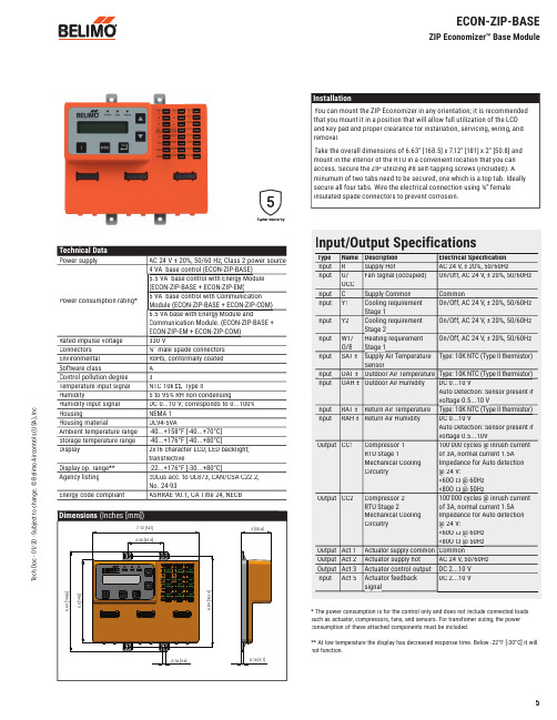
T e c h .D o c - 01/20 - S u b j e c t t o c h a n g e . © B e l i m o A i r c o n t r o l s (U S A ), I n c .Input/Output SpecificationsType Name Description Electrical Specifi cation Input RSupply HotAC 24 V, ± 20%, 50/60HzInputG/OCCFan Signal (occupied)On/Off, AC 24 V, ± 20%, 50/60Hz Input C Supply Common CommonInput Y1Cooling requirement Stage 1On/Off, AC 24 V, ± 20%, 50/60Hz Input Y2Cooling requirementStage 2On/Off, AC 24 V, ± 20%, 50/60Hz Input W1/O/B Heating requirement Stage 1On/Off, AC 24 V, ± 20%, 50/60Hz Input SAT ±Supply Air TemperatureSensorType: 10K NTC (Type II thermistor)Input OAT ±Outdoor Air Temperature Type: 10K NTC (Type II thermistor)InputOAH ±Outdoor Air HumidityDC 0...10 VAuto Detection: Sensor present if voltage 0.5...10 VInput RAT ±Return Air Temperature Type: 10K NTC (Type II thermistor)Input RAH ±Return Air Humidity DC 0...10 VAuto Detection: Sensor present if voltage 0.5 (10V)Output CC1Compressor 1RTU Stage 1Mechanical Cooling Circuitry 100'000 cycles @ inrush currentof 3A, normal current 1.5A Impedance for Auto detection @ 24 V:<60O Ω @ 60Hz <80O Ω @ 50HzOutputCC2Compressor 2RTU Stage 2Mechanical CoolingCircuitry100'000 cycles @ inrush currentof 3A, normal current 1.5A Impedance for Auto detection @ 24 V:<60O Ω @ 60Hz <80O Ω @ 50HzOutput Act 1Actuator supply common Common Output Act 2Actuator supply hot AC 24 V, 50/60Hz Output Act 3Actuator control output DC 2...10 V Input Act 5Actuator feedback signalDC 2...10 VInstallationYou can mount the ZIP Economizer in any orientation; it is recommended that you mount it in a position that will allow full utilization of the LCD and key pad and proper clearance for installation, servicing, wiring, and removal.Take the overall dimensions of 6.63" [168.5] x 7.12" [181] x 2" [50.8] and mount in the interior of the RTU in a convenient location that you can access. Secure the ZIP utilizing #8 self-tapping screws (included). A minumum of two tabs need to be secured, one which is a top tab. Ideally secure all four tabs. Wire the electrical connection using ¼” female insulated spade connectors to prevent corrosion.Technical DataPower supplyAC 24 V ± 20%, 50/60 Hz; Class 2 power source Power consumption rating*4 VA base control (ECON-ZIP-BASE)5.5 VA base control with Energy Module (ECON-ZIP-BASE + ECON-ZIP-EM)5 VA base control with Communication Module (ECON-ZIP-BASE + ECON-ZIP-COM)6.5 VA base with Energy Module andCommunication Module. (ECON-ZIP-BASE + ECON-ZIP-EM + ECON-ZIP-COM)Rated impulse voltage 330 VConnectors ¼” male spade connectors Environmental RoHS, conformally coated Software classA Control pollution degree 3Temperature input signal NTC 10k Ω, Type IIHumidity5 to 95% RH non-condensingHumidity input signal DC 0...10 V; corresponds to 0...100%HousingNEMA 1Housing materialUL94-5VAAmbient temperature range -40...+158°F [-40...+70°C]Storage temperature range -40...+176°F [-40...+80°C]Display2x16 character LCD; LED backlight; transflectiveDisplay op. range**-22...+176°F [-30...+80°C]Agency listing cULus acc. to UL873, CAN/CSA C22.2, No. 24-93Energy code compliantASHRAE 90.1, CA Title 24, NECBDimensions (Inches [mm])7.12 [181]2.42 [61.6]0.18 [4.6]6.04 [153.4]5.5 [140]6.63 [168.5]2 [50.8]0.16 [4.1]ECON-ZIP-BASEZIP Economizer™ Base Module* The power consumption is for the control only and does not include connected loads such as actuator, compressors, fans, and sensors. For transfomer sizing, the power consumption of these attached components must be included.** At low temperature the display has decreased response time. Below -22°F [-30°C] it will not function.T e c h .D o c - 01/20 - S u b j e c t t o c h a n g e . © B e l i m o A i r c o n t r o l s (U S A ), I n c .ECON-ZIP-BASEZIP Economizer™ Base Module Wiring DiagramsR CG OCC W1O/B Y1Y2ACT1ACT2ACT3ACT5R C R CG/OCC W1/O/B Y1Y2CC1CC2OAT+OAT-OAH+OAH-SAT+SAT-RAT+RAT-RAH+RAH--SR1 -Common2 + Hot3 Y Input, 2 to 10V 5 U Output, 2 to 10VACT 1ACT 2ACT 3ACT 5R CY1Y2ECON-ZIP-10K Supply Air TempSAT +SAT -OAT + OAT -CC1CC2OCC W1RTU Stage 1 Mechanical CoolingCircuitryRTU Stage 2 Mechanical CoolingCircuitryECON-ZIP-10K Outside Air TempTHERMOSTATRTU TERMINALECON-ZIP-BASE575251535659R CG OCCW1O/B Y1Y2ACT1ACT2ACT3ACT5R C R CG/OCC W1/O/B Y1Y2CC1CC2OAT+OAT-OAH+OAH-SAT+SAT-RAT+RAT-RAH+RAH--SR1 -Common2 + Hot3 Y Input, 2 to 10V 5 U Output, 2 to 10VACT 1ACT 2ACT 3ACT 5R CY1Y2ECON-ZIP-10K Supply Air Temp SAT +SAT -CC1CC2OCC W1RTU Stage 1 Mechanical CoolingCircuitry RTU Stage 2 Mechanical CoolingCircuitryECON-ZIP-TH Outside Air EnthalpyT (+)T (-)24 V (R)RH (+)RH (-)OAT + OAT -OAH + OAH - RECON-ZIP-BASETHERMOSTATRTU TERMINAL57505251535659When the thermostat is not equipped with occupancy control, "Fan On" output "G" shall be wired to the ECON-ZIP-BASE.W1 must be wired for Heat Pump operation if conventional thermostat is used in conjunction with Defrost Board. If Thermostat and RTU use O/B control reversing valve position, O/B must be wired to W1 on ECON-ZIP-BASE.Existing refrigeration safety devices may exist, consult RTU wiring diagram515253If RTU is not a Heat Pump using a conventional thermostat and it is desired to record heating operation hours, connect W1 to ECON-ZIP-BASE.56Actuators can be mounted in parallel with the ACT3 output from the ZIP Economizer. The ACT5 feedback input should be wired to the Outside Air damper actuator feedback wire.57Iso relay may be required with certain RTU manufacturers.59Power source should be the same as ECON-ZIP-BASE.50When the thermostat is not equipped with occupancy control, "Fan On" output "G" shall be wired to the ECON-ZIP-BASE.Existing refrigeration safety devices may exist, consult RTU wiring diagram5153If RTU is not a Heat Pump using a conventional thermostat and it is desired to record heating operation hours, connect W1 to ECON-ZIP-BASE.56W1 must be wired for Heat Pump operation if conventional thermostat is used in conjunction with Defrost Board. If Thermostat and RTU use O/B control reversing valve position, O/B must be wired to W1 on ECON-ZIP-BASE.52Actuators can be mounted in parallel with the ACT3 output from the ZIP Economizer. The ACT5 feedback input should be wired to the Outside Air damper actuator feedback wire.57Thermostat with two (2) stages of cooling required. Thermostats with mercury switches are not compatible with the ZIP Economizer.58Iso relay may be required with certain RTU manufacturers.59T e c h .D o c - 01/20 - S u b j e c t t o c h a n g e . © B e l i m o A i r c o n t r o l s (U S A ), I n c .R CG/OCCW1/O/BY1Y2ACT1ACT2ACT3ACT5R C R CG/OCC W1/O/B Y1Y2CC1CC2OAT+OAT-OAH+OAH-SAT+SAT-RAT+RAT-RAH+RAH--SR1 -Common2 + Hot3 Y Input, 2 to 10V 5 U Output, 2 to 10VACT 1ACT 2ACT 3ACT 5R CY1Y2ECON-ZIP-10K Supply Air Temp SAT +SAT -OAT + OAT -CC1CC2G/OCC W1/O/BRTU Stage 1 Mechanical CoolingCircuitry RTU Stage 2 Mechanical CoolingCircuitryECON-ZIP-TH Outside Air EnthalpyECON-ZIP-THRAT+T (+)T (-)24 V (R)RH (+)RH (-)RAT-RAH+RAH-RT (+)T (-)24 V (R)RH (+)RH (-)OAH + OAH - RECON-ZIP-BASETHERMOSTATRTU TERMINAL5859R CG/OCC W1/O/BY1Y2ACT1ACT2ACT3ACT5R C R CG/OCC W1/O/B Y1Y2CC1CC2OAT+OAT-OAH+OAH-SAT+SAT-RAT+RAT-RAH+RAH--SR1 -Common2 + Hot3 Y Input, 2 to 10V 5 U Output, 2 to 10VACT 1ACT 2ACT 3ACT 5R CY1Y2ECON-ZIP-10K Supply Air TempSAT +SAT -OAT + OAT -THERMOSTATRTU TERMINALCC1CC2G/OCC W1/O/BRTU Stage 1 Mechanical CoolingCircuitry RTU Stage 2 Mechanical CoolingCircuitryECON-ZIP-10K Outside Air TempECON-ZIP-10K Return Air TempRAT+ECON-ZIP-BASE57RAT-59Power source should be the same as ECON-ZIP-BASE.50When the thermostat is not equipped with occupancy control, "Fan On" output "G" shall be wired to the ECON-ZIP-BASE.Existing refrigeration safety devices may exist, consult RTU wiring diagram5153If RTU is not a Heat Pump using a conventional thermostat and it is desired to record heating operation hours, connect W1 to ECON-ZIP-BASE.56W1 must be wired for Heat Pump operation if conventional thermostat is used in conjunction with Defrost Board. If Thermostat and RTU use O/B control reversing valve position, O/B must be wired to W1 on ECON-ZIP-BASE.52Actuators can be mounted in parallel with the ACT3 output from the ZIP Economizer. The ACT5 feedback input should be wired to the Outside Air damper actuator feedback wire.57Thermostat with two (2) stages of cooling required. Thermostats with mercury switches are not compatible with the ZIP Economizer.58Iso relay may be required with certain RTU manufacturers.59Power source should be the same as ECON-ZIP-BASE.50When the thermostat is not equipped with occupancy control, "Fan On" output "G" shall be wired to the ECON-ZIP-BASE.Existing refrigeration safety devices may exist, consult RTU wiring diagram5153If RTU is not a Heat Pump using a conventional thermostat and it is desired to record heating operation hours, connect W1 to ECON-ZIP-BASE.56W1 must be wired for Heat Pump operation if conventional thermostat is used in conjunction with Defrost Board. If Thermostat and RTU use O/B control reversing valve position, O/B must be wired to W1 on ECON-ZIP-BASE.52Actuators can be mounted in parallel with the ACT3 output from the ZIP Economizer. The ACT5 feedback input should be wired to the Outside Air damper actuator feedback wire.57Thermostat with two (2) stages of cooling required. Thermostats with mercury switches are not compatible with the ZIP Economizer.58Iso relay may be required with certain RTU manufacturers.59ECON-ZIP-BASEZIP Economizer™ Base Module Wiring DiagramsT e c h .D o c - 01/20 - S u b j e c t t o c h a n g e . © B e l i m o A i r c o n t r o l s (U S A ), I n c .ZIP EconomizerQuick SetupMoves up through the menu on the same level. Will increase values by one increment at a time. When setting values holding key down willfast scrollMoves down through the menu on the same level. Will decrease values by one increment at a time. When setting values holding key down will fast scroll. Enter sub menu level. Start editing a setting. Store an entered value. esc Escape sub menu tonext higher level.Cancel current actions.iShow additional information on thecurrent menu Itemwhen “i” appears inlower right of display.Moves down through the menu on the same level.Will decrease values by one increment at a time. When setting values holding key down will fast scroll.Enter sub menu level.Start editing a setting. Store an entered value. esc Escape sub menu to next higher level.Cancel current actions.iShow additional information on the current menu Item when “i” appears in lower right of display.Functions1. “Monitor Live Conditions” is used to display settings and live values.2. “Settings” is used to parameterize the ZIP Economizer. (Note: Devices 1 is for CC1, CC2, EF, IF; Devices 2 is for OAH, RAH)3. “Present Devices” is used to verify that the ZIP Economizer's Auto Detected connections are terminated properly. If connected device is not shown, verify wiring. If wiring has continuity and device is verifi ed operational re-enter “Settings” and enable missing device by changing from “Auto” to “Available” or “Installed”.4. “Alarms” is used to view current and historical alarms and delete inadvertently caused alarms.5. “Service and Commissioning” submenu is used to operate the RTU in “Manual Mode” or to perform “Acceptance Test”. “Settings” must to be completed to access.6. “Status” is a display of the current operating mode. It can beaccessed by pressing ”esc”. The action of pressing any key will drop the user down from Status to the next level, so repeatedly pressing “esc” will toggle the display between Status and Monitor Live Conditions. (Note: If status “Setup incomplete” is displayed the RTU cooling operation will be disabled and additional parameters must be set to achieve “Setup complete”.)1. Shut off power to RTU before beginning installation.2. Note orientation, opening rotation, and spring return rotation of damper assembly. Mount Actuator to Outside Air and Return Damper assembly. To ensure tight outside air shutoff; while tightening actuator clamp push damper closed.3. Terminate required Inputs and Outputs(I/O): For the ZIPEconomizer to function correctly, the following I/O, at a minimum, are required to be terminated, wired, and functioning (R, C, Y1, Y2, G, CC1, OAT, SAT, ACT1, ACT2, ACT3, ACT5). See wiring diagrams.4. Sensor confi guation: The ZIP Economizer automatically detects sensors attached and automatically confi gures for single dry bulb, single enthalpy, differential dry bulb and differential enthalpy.“Settings” is the menu displayed when the ZIP Economizer is fi rstpowered. Press “OK” to parameterize required settings. Reference above Keypad Key defi nition instructions and navigate as needed.WARNING Live Electrical Components!During installation, testing, servicing and troubleshooting of this product, it may be necessary to work with live electrical components. H ave a qualifi ed licensed electrician or other individual who has been properly trained in handling live electrical components perform these t asks. Failure to follow all electrical safety precautions when exposed to live electrical components could result in death or serious injury.T e c h .D o c - 01/20 - S u b j e c t t o c h a n g e . © B e l i m o A i r c o n t r o l s (U S A ), I n c .1. ZIP Code US or Canada (sets the free cooling changeover high limit and temperature units F/C)a. When the Zip Code submenu is displayed enter “OK” to begin “US” Zip Code parameterization. If “Canada” Postal Code is desired press the up/down arrow to access.i. Press OK to access digit 1 (flashing) then use the up/down arrow to parameterize; enter OK when complete. Repeat until all digits are complete. If a mistake is made press “esc” andrepeat from beginning.ii. When all Zip Code or Postal Code digits are entered press “esc” to move up a level then press the up/down arrow to access next settings parameter.2. Vent Min Pos (Outdoor Air Damper Ventilation Minimum Position)a. When the “Vent Min Pos” submenu is displayed press “OK” toparameterize (flashing).b. Use the up/down arrow to parameterize, press “OK” whencomplete. The actuator will immediately drive the damper to the minimum position.3. Additional Parameters may require setting. The ZIP Economizer will auto-detect added Devices such as a CO2 sensor etc. When the ZIP Economizer detects a new device, it will prompt the user in the Status level; navigate to Settings and parameterize blank fi elds. If the devices are connected upon fi rst start up their settings will require parameterization then.4. When all parameters have been set, the ZIP Economizer will show “Setup Complete” if there are still parameters to set, there will be no action. You can verify by pushing esc until status level is reached and it will display “Setup Incomplete”. If this is the case, re-enter settings menu and use up down arrows to fi nd the parameter with blank fi elds and parameterize as described above. Note: you may enter parameters in any order - eg: Vent min Pos before ZIP Code - If the RTU is a heat pump or uses a 2 speed indoor fan, these paramaters should be enabled fi rst, otherwise the logic may go to Setup Complete prematurely.The ZIP Economizer has built in commissioning processes found in Acceptance Test.1. Economizer Test. Use “Economizer Test” to verify RTU Integrated Economizer operation. Navigate to the “Service and Commissioning” menu, press “OK”; press the down arrow to access “Acceptance Test”. Press OK again when “Economizer Test” appears. Press “OK” again to confi rm running test. Follow prompts during test. This test will open damper to 100%, enable power exhaust fan (if connected), enable 1st stage of Mechanical Cooling, reverse this process and then drive to Vent Min Position. When used with a Belimo actuator, the actuator will speed up to reduce test time.2. Manual Mode is used to override outputs after entering a “Timeout” duration.3. Damper Scaling. The test will re-scale the control signal range to maximum resolution (0...100%) over the calibrated (reduced) angle. When using a Belimo actuator, the actuator will speed up to reduce test time.Note: Failure to identify obstructions or improper setup of damper assembly may result in an improper scaling and operation of the damper.)Additional testing can be found later in this document.1. When all entries have been completed, the ZIP Economizer will switch to Status display and show “Setup Complete”, and will immediately show a “Damper scaling starts in 10secs” and will countdown to 0 (be aware, at 0 the damper will start to move at high speed ). A message will scroll saying “Damper scaling for better operation if obstruction is present rescale damper in commissioning menu”. (For detailed instructions on this – please see the section “Service and Commissioning” below. This will open damper to 100% (re-scale control signal if needed). (Note: failure to identify obstructions or improper setup of damper assembly may result in an improper scaling and operation of the damper.)Once scaling is complete, a message will appear saying “Damper scaling successful”. The ZIP will then show “maximum at80° = 100%” That message will show maximum rotation of the damper. This process ensures the damper is always operating and displayed from 0...100%.2. Once the message has appeared, the actuator immediately closes the damper and a countdown begins, until the unit starts to operate in Automatic Mode (be aware, when countdown complete, the RTU will respond to thermostat calls which may enable mechanical cooling).ZIP EconomizerQuick Setup。
- 1、下载文档前请自行甄别文档内容的完整性,平台不提供额外的编辑、内容补充、找答案等附加服务。
- 2、"仅部分预览"的文档,不可在线预览部分如存在完整性等问题,可反馈申请退款(可完整预览的文档不适用该条件!)。
- 3、如文档侵犯您的权益,请联系客服反馈,我们会尽快为您处理(人工客服工作时间:9:00-18:30)。
6.2 03.2015•S u b j e c t t o m o d i fi c a t i o n
Damper actuator for adjusting air control dampers in ventilation and air-conditioning systems for building services installations • Torque 4Nm
• Nominal voltage AC/DC 24V • Control: Open-close
(not made for 3-point applications)• Running time 2.5s
Electrical data
Nominal voltage
AC 24V, 50/60Hz / DC 24V
Nominal voltage range AC 19.2...28.8V / DC 21.6...28.8V Power consumption In operation At rest
For wire sizing
13W @ nominal torque 2W
23VA (I max. 20A @ 5ms)Connection
Cable 1m, 3 x 0.75mm ²
Functional data
Torque (nominal torque)Min. 4Nm @ nominal voltage
locked
Angle of rotation
Max. 95°, can be limited at both ends with adjustable mechanical end stops Angle of rotation limiting min. 30°Running time
2.5s / 90°
Automatic adjustment of
operating range to match the mechanical angle of rotation Manual triggering of the adaption by pressing the «Adaption» button
Sound power level 52dB(A)
Position indication Mechanical, pluggable
Negative torque
!
≤50% from nominal torque (with restrictions)*
Safety
Protection class III Safety extra-low voltage UL Class 2 Supply
Degree of protection IP54 in any mounting position NEMA 2, UL Enclosure Type 2EMC
CE according to 2004/108/EC
Certification
Certified to IEC/EN 60730-1 and IEC/EN 60730-2-14 cULus according to UL 60730-1A and UL 60730-2-14 and CAN/CSA E60730-1:02Mode of operation Type 1Rated impulse voltage 0.8kV Control pollution degree 3
Ambient temperature
–30...+40°C (no restrictions)!
+40...+50°C (with restrictions)*Non-operating temperature –40...+80°C
Ambient humidity 95% r.H., non-condensating Maintenance
Maintenance-free Dimensions / Weight
Dimensions See «Dimensions» Weight
Approx. 0.97kg
Dimensional drawings
Dimensions [mm]
* Option (accessory K-NA)
When using an auxiliary switch or feedback potentiometer.
Technical data
* Under these operating conditions, the lift cycle of actuator will be reduced. Please contact your Belimo representative for details
a t i o
n
Modulating damper actuator for adjusting air control dampers in ventilation and air-conditioning systems for building services installations • Torque 4Nm
• Nominal voltage AC/DC 24V
• Control: modulating DC (0)2...10V • Position feedback DC 2...10V • Running time 2.5s
Dimensional drawings
Dimensions [mm]
6.2 03.2015•S u b j e c t t o m o d i fi c a t i o n
Wiring diagrams: Open/Close actuators – parallel connection possible, please note the performance data Wiring diagrams: Modulating actuators – parallel connection possible, please note the performance data Wiring diagrams: Open/Close actuators—parallel connection possible, please note the performance data.
Wiring diagram: Modulating actuators—parallel connection possible, please note the performance data.
Direction of rotation
Position - signal voltage。