VERICUTv71_release_notes
Vericut 7.0教程 新功能
Vericut 7.0 新功能Vericut 7.0的增强功能亮点加强了项目树(Project Tree)功能,减少了弹出对话框的数量,我们只要通过导航就可以创建一个仿真项目。
Vericut 7.0在创建仿真项目方面与Vericut 6.2是有很大区别的。
●项目必须通过项目树来配置。
●以前版本中那些弹出对话框中的常用功能,都放置到项目树中。
●选定项目树中的任意节点,在项目树的底部都会出现此节点的配置菜单。
●在项目树中还增加了一种新的文件选择方法●在项目树配置菜单中的更改会直接应用,而不需要按“确定”、“应用”、“取消”等按钮。
●由于项目树中也可以显示机床组件,则取消了组件树。
现在的项目树能引导您使用项目树的各种功能完成一个项目中的所有的设置的配置,例如:●通过项目树从上到下的结构,可以完成项目树中所有的节点的配置。
●在创建和配置某一个设置的过程中,可以有选择的在项目树底部显示配置面板。
●配置面板中显示的设置操作都是配置项目时最常用的。
●配置面板中显示的设置功能是根据项目树中选定的各个节点而不同,是各节点特有的。
●在配置面板中的任何操作(填写的文字和数字、确认的选项、或点击的按钮)都会直接应用,不需要你按“确定”、“应用”等等。
●不常用的功能可以通过鼠标右键项目树中各个节点弹出的快捷菜单,或者通过左键单击菜单工具栏弹出的对话框来设定。
VERICUT在计算和动画仿真NC代码的运动轨迹时,采用了一种新的方法。
● 动画运动在所有的视图里都是等同的。
● 在不同的视图类型中刀具的显示是一样的。
● 对于所有的动作类型和视图类型,放慢和跳跃切削都是一样的。
● 碰撞公差和运动显示是相互独立的。
功能的增强刀轨和机床验证*VC增加了模拟自动倒圆、自动倒角的功能:approaching/departing, inside/outside, and CW/CCW.*工具条可以完全用户定制。
每个人可以根据自己的需要添加或去掉某些按钮,并且可以调整按钮的显示顺序。
[整理]VERICUT入门常见问题.
![[整理]VERICUT入门常见问题.](https://img.taocdn.com/s3/m/75b6b93754270722192e453610661ed9ad515582.png)
[整理]VERICUT入门常见问题.VERICUT入门常见问题[attach]46[/attach]Vericut 7.0 教材VERICUT入门常见问题作者:artcnc工作组问题1:为什么要进行机床模拟、程序仿真、程序优化?笔者曾亲眼所见一个例子:某大学的校办工厂的一个操作工人在操作机床时由于没有仔细的检查NC程序,造成了机床碰撞,导致刀具被撞断,机床主轴损坏,零件成批报废,这次事故的后果是很严重的,因为该机床是一台高精度机床五坐标加工中心,专门进行零件精加工,其经济附加值比较高,机床停止就是造成了经济损失,而且机床主轴损坏后的更换是一笔非常昂贵的费用,加工的零件又是火车机车上一个比较关键的零件,其加工难度大,加工周期长,是一个瓶颈零件,零件加工到此,已经完成了大部分的工序,零件报废的经济损失是很大的,并且由于零件的报废、机床的维修都耽误了零件的交付进度。
机床碰撞是很严重的事故,所有的工程技术人员或CNC编程人员,都应该意识到这一点,避免数控机床发生碰撞是我们的责任和义务。
怎样才能做好这一点呢?首先要做到的就是正确的设计工艺加工方案,正确无误的编制数控加工程序,并做到认真复查、仔细校对,除此之外,我们还需要借助一些软件来帮我们模拟机床运动,检查碰撞。
随着机床的复杂化、智能化和机械加工自动化,对于一些复杂的零件仅仅靠NC 编程已经不能完成零件的机械加工,机床的模拟仿真就像设计工艺方案、编写数控加工程序一样,在零件的加工过程中已经扮演越来越重要的角色,机床的模拟仿真、避免机床碰撞已经是机械加工中不可或缺的一部分。
[url]/doc/8918067565.html,[/url] [email]Artcnc@/doc/8918067565.html,[/email]Vericut 7.0 教材问题2:VERICUT的优秀用户其实,对于机床的模拟、程序的仿真和优化有很多知名的大大公司在这方面都做的很好。
第1章 Vericut功能概述

第1章Vericut功能概述1.1 本章要点和学习方法本章重点介绍Vericut常用的功能,同时对软件的菜单布局、常用功能进行介绍,通过仿真训练引导读者尽快入门。
本章是基础,初学者需要打开Vericut 7.3软件,根据书上的提示进行操作。
1.2 Vericut软件简介Vericut软件是美国CGTech公司出品的一款优秀的数控加工仿真软件,尤其在多轴加工方面功能强大、可靠性高,为广大多轴用户优化数控程序、有效利用设备提供了很大的帮助,应用这款软件可以提前预防撞刀、过切等加工事故的发生,因此在数控加工行业得到了广泛的应用。
1.3 Vericut的作用简单地说,Vericut软件可以对数控程序进行仿真,以检查其合理性和可行性,消除加工中可能出现的错误,提高加工效率。
1.4 Vericut的功能(1)机床运动模拟。
(2)数控程序加工仿真。
(3)零件加工结果分析。
(4)数控加工程序优化。
(5)车间文档制作,如工艺报告、测量报告。
(6)辅助分析及测量报告。
1.5 虚拟仿真和实际加工的关系(1)计算机里的“撞机”再严重都不怕,而实际加工中的撞机会导致严重的后果。
(2)虚拟加工是现代制造技术中最卓越的科研成果。
(3)虚拟加工是实际加工的前期检查及验证。
(4)如果虚拟加工出现错误,必须要分析原因及时纠错,否则会导致加工错误。
(5)要得到可靠的加工检验结果,其构建的机床模型、刀具、夹具、装夹方法以及数控程序都要和实际加工吻合,至少要做到与重要加工要素吻合。
1.6 Vericut 7.3界面介绍Vericut 7.3界面的菜单及工具栏很多,这里仅介绍最为常用且很重要的部分功能,另外部分功能还要在后续章节的实例特训中给予介绍。
1.6.1 Vericut 7.3软件的初始界面在桌面上双击Vericut 7.3的图标,或者从Windows界面的【开始】菜单中执行【所有程序】||命令,即可启动Vericut 7.3软件。
Vericut中文版

当我们建立好组件了以后,接下来就是要决定它的位置。按下 Position 后,会看到下面 的窗口。
图 1 Component Tree (c). 接下来点选 Base,所谓 Base,可以将其想象成机台中所有不会动的部份, 都可以称其为 Base。按下鼠标右键,选择 Component Attributes,就会出现 Model 的对话窗口。在 Type 里选择 Model File,然后再选择转存出来的 STL 档案,接 着在 Color 里,选择颜色。完成之后,按下 Add 钮就会增加到 Component Tree 里了。而就可以在绘图区里看到 Base 了,如图 2。
图 6 主轴之建构 (g). 再来要建构的是 X 轴,X 轴是与 Base 相关联的,所以对着 Base Append 一个 X Linear,再将其移动位置,完成后如图 7。
图 7 X 轴之建构 (h). 接着要建构夹具(Fixture),夹具是与 X 轴关联的,但是在高速加工机的 模型中,因为没有绘制虎钳之类的夹具,而是直接将工件置于 X 轴上,所以就直 接在 X 轴下 Append 一个 Fixture 并将原先有个夹具删除,再将其移动到正确的 位置,注意的是夹具的移动也是属于 Component 的移动。如果需要侦测刀具是否 会在切削过程中碰撞夹具的话,可以绘制虎钳来模拟。建构完成后如图 8。
对于我们建构一台加工机而言,最重要的就是其各组件的关联性与其位置了,其中又以 关联性为最重要的,所以我们在建构时需特别注意,以免发生各轴之间的移动问题。下图是 我们决定好各组件的位置及关联性后的完成图。
EZiPCC_v7_7_Release_Note_CHS
EZiPCC v7.7发布说明(内部参考)2010/1/15版权©2010 亿迅(中国)软件有限公司版权保护声明未经亿迅(中国)软件有限公司书面许可,本文档任何部分的内容不得被复制或抄袭用于任何目的。
目录1.概观 (3)2.功能介绍 (3)2.1.CTI基础平台 (4)2.1.1.IP PBX (4)2.1.2.IVR Server (4)2.1.3.语音流程图形化设计工具(Routing Designer) (6)2.1.4.CTI Server (7)2.1.5.Stat服务 (7)2.1.6.Configuration服务 (7)2.1.7.通信服务 (7)2.2.话务应用 (8)2.3.系统管理平台 (8)2.4.客服中心业务应用 (8)2.4.1.话术脚本设计工具(Agent Script Designer) (9)2.4.2.问卷设计工具(QForm Designer) (11)2.4.3.电话营销活动管理模块 (11)2.4.4.窗体应用模块 (12)2.4.5.业务应用范本 (12)3.发布声明 (13)3.1.发布版本号 (13)3.2.新增功能 (13)3.2.1.PBX & Admin Center (13)3.2.2.IVR & Routing Designer (13)3.2.3.Agent Desktop (14)3.3.调整功能 (14)3.3.1.PBX & Admin Center (14)3.3.2.IVR & Routing Designer (14)3.3.3.Fax (15)3.3.4.Agent Desktop (15)3.3.5.话术脚本设计工具(Agent Script Designer) (16)3.3.6.问卷管理 (17)3.3.7.电话营销活动管理模块 (17)3.3.8.窗体应用模块 (17)3.3.9.License 控制模块 (17)3.3.10.Sys Admin (18)3.3.11.JAVA JRE侦测与安装 (18)3.4.修正功能 (18)3.4.1.PBX (18)3.4.2.Admin Center (19)3.4.3.IVR & Routing Designer (19)3.4.4.Fax (20)3.4.5.Agent Desktop (20)3.4.6.话术脚本设计工具 (21)3.4.7.问卷管理 (21)3.4.8.电话营销活动管理模块 (22)3.4.9.窗体应用模块 (23)3.4.10.Sys Admin (23)4.相关文档 (24)1. 概观EZiPCC 是亿迅因应Web普及与IP技术成熟的趋势,运用IP软交换机,及亿迅在客服中心应用软件多年深耕水到渠成的基础下,提出的客服中心整体解决方案产品。
vericut 软件介绍
VERICUT仿真软件VERICUT是由美国CGTech公司开发的一款数控加工仿真软件件,是利用软件在计算机上虚拟制造过程,采用了先进的三维显示及虚拟现实技术,可以验证和检测NC程序可能存在的碰撞、干涉、过切、欠切、切削参数不合理等问题。
从1988年起,VERICUT就成为行业的标准,被广泛的应用于航空航天、兵器、船舶、电子、汽车、地面交通、模具、消费品、动力及重工业。
产品特点及优势:1. Vericut是基于实体的、基于特征的并记录历史的仿真,所以通过Vericut生成的具有历史和特征的切削模型,可以方便、准确、快速地分析尺寸,检测错误。
而一般软件不是基于特征的实体仿真,模拟后的这些加工特征已经丢失,这样缺点是切削模拟精度不高,模型数据量大,模拟速度不温度,会越来越慢,分析测量模型不方便。
2. Vericut仿真是和实际生产完全匹配的,是对整个生产流程的模拟。
一个零件的生产,从毛料到粗加工到半精加工再到精加工,切削模型可以在不同机床不同系统不同夹具中自动转移。
一般软件只是简单的单工位模拟,不支持零件整个生产流程的模拟,零件翻面或换机床模拟操作不方便。
3. Vericut 在程序模拟之前(预览程序),模拟过程中或模拟结束三个阶段都可以分析检测各种错误,包括:过切、碰撞、超程、旋转方向、极限切削参数(最大切削深度、最大切削宽度、最大切削速度、最大切削转速、最大材料去除率等)等。
而且程序窗口、图像窗口和错误信息栏窗口三个窗口相互关联,分析定位错误直接直观。
4. Vericut检查分析过切有曲面和实体两种方式,而且可以直接定位到特定程序特定程序行发生的过切,这样更方便更直观。
5. 模型输出。
VERICUT在模拟切削过程的任何阶段,都可以将具体加工特征(孔,槽,凸台,腹板,筋等)的切削模型输出,以不同的数据标准格式保存,如Step,IGS,ACIS,CATIA V5等格式。
Vericut是基于特征的模拟,可以输出具有加工特征的模型供后续操作。
VERICUT软件安装步骤V7.4.2
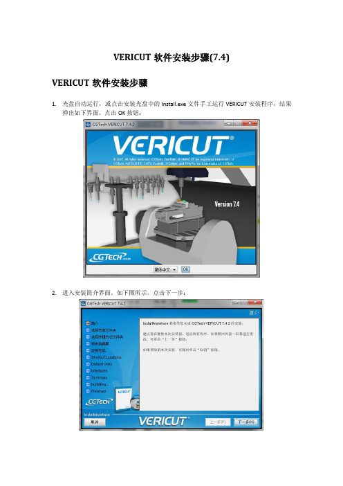
VERICUT软件安装步骤(7.4) VERICUT软件安装步骤1.光盘自动运行,或点击安装光盘中的Install.exe文件手工运行VERICUT安装程序,结果弹出如下界面。
点击OK按钮:2.进入安装简介界面。
如下图所示。
点击下一步:3.进入许可协议界面,确认选择“本人接受许可协议条款”项,点击下一步4.进入选择安装文件夹界面,选择软件安装的位置,点击下一步:5.进入选择安装类型界面。
默认选择第一个全部选项,点击下一步6.进入口令服务选择界面。
如果是服务器安装,则选第三个选择:在这台电脑安装口令服务。
如果是客户端安装,则选第一个选择:使用远程电脑的现有口令服务,并输入服务器电脑名或者服务器电脑IP地址7.选择安装软件快捷方式,请勾选第一项创建桌面快捷方式8.进入VERICUT软件模式选择界面。
默认选择正常VERICUT软件模式安装9.进入默认单位选择界面。
默认选择毫米单位。
点击下一步。
10.进入选择接口安装界面。
选择需要装的模型接口或CAM软件接口,点击下一步11.进入安装最后的确认界面。
确认无误后,点击安装按钮:12.安装完成界面。
如果在第6步选择的是第三项:在这台电脑安装口令服务,则勾选运行口令服务安装,点击下一步进入新的口令服务安装界面。
点击下一步。
13.VERICUT软件安装完成。
14.如果勾选了口令服务安装,则会自动弹出新的口令服务软件安装界面(也可以在安装光盘下双击运行license_server_install.exe手动启动此界面):15.进入口令服务软件安装简介界面:16.进入口令服务软件安装许可协议界面:17.选择口令服务软件安装路径:18.选择口令服务软件安装快捷方式:19.确认口令服务软件安装信息,然后点击安装:20.口令服务软件安装完成21.运行开始程序---CGTech口令服务---License Server Only---Configure License&Setup Server,进入口令安装DOS界面(也可以手动从软件安装路径C:\Program Files\CGTech\License Server下,双击运行setup_license_server.bat进入此界面)22.按任意键继续23.再按任意键,弹出创建VERICUT口令文件窗口。
vericut7.0破解方法
安装vericut7.0时遇到口令服务器找到,但是没有找到CGTech口令信息和无效的临时口令文件无法执行程序等问题的解决方法这是破解文件的原因(前提是严格按照安装步骤安装)。
1、必须将所有的安全卫士杀毒软件等防护软件退出,并将UAC设置为最低,主题元素为“windows经典”。
2、将下面的代码覆盖到原来的\cgtech70\windows\license\cgtech.if文件里的内容,复制并保存;然后单击“开始”---程序-- CGTech VERICUT 6.2----- License Server Only--- Configure License & Setup Server,根据提示会出现一个对话框,将刚复制的内容粘贴进去,别的不用管,关闭就可以了。
按照提示知道按任意键DOC框退出。
3、单击“开始”---程序-- CGTech VERICUT 6.2----- License Server Only----- start License server service。
4、单击“开始”---程序-- CGTech VERICUT 6.2----- License Server Only----- update License on running server。
(这步非常重要!)5、打开软件,如果出现什么系统时间不对(那个具体错误命令忘了,就是这个意思),转入下一步6、停止Vericut 的License 系统服务(服务名为“Sentinel RMS LicenseManager”)7、删除系统目录System32 下的文件“servdat.slm”8、删除注册表中“HKEY_LOCAL_MACHINE\SOFTWARE\Ntpad”键9、重新启动Vericut 的License 系统服务(即重复3、4步)另外,对于安装软件时出现“无效的临时口令文件无法执行程序”的问题,也可用这种方法解决。
- 1、下载文档前请自行甄别文档内容的完整性,平台不提供额外的编辑、内容补充、找答案等附加服务。
- 2、"仅部分预览"的文档,不可在线预览部分如存在完整性等问题,可反馈申请退款(可完整预览的文档不适用该条件!)。
- 3、如文档侵犯您的权益,请联系客服反馈,我们会尽快为您处理(人工客服工作时间:9:00-18:30)。
What's NEW in VERICUT 7.1 IMPORTANT! - Licensing is NOTincluded in software shipments. See"How to get a license" below fordetails.December 29, 2010Dear VERICUT® User:Thank you for your continued investment in VERICUT, an important part of your NC programming and machining process!The VERICUT 7.1’s NC program simulation, verification, and optimization technology is packed with new features making it more powerful and easier to use. This letterdescribes important changes in VERICUT 7.1. Take a moment to review what's new and improved in this release.Maintenance and Licensing InformationSoftware maintenance keeps you on the cutting edge - CGTech provides update software to customers with current software maintenance. Your continued maintenance ensures that you have the most advanced verification technology available. If your maintenance has expired, please contact your CGTech representative(/usa/cgtech/contact/).Sincerely,Bill HasenjaegerCGTech Product MarketingHow To Get a License - All users must complete and return the License Request Form in the CD booklet, or submit the application at/usa/support/license/. Licensing is sent via Email only.NOTE: This software requires a VERICUT 7.1 license.VERICUT 7.1Release NotesDecember 29, 2010VERICUT 7.1 EnhancementsHighlightsAs of V7.1, VERICUT is no longer supported on UNIX. A UNIX computer can still be used to run the VERICUT License Server program.Support is added for the simulation of 6-axis Cartesian arm industrial robots (Fanuc, Kuka, ABB, Kawasaki, Motorman, etc.). Support includes support for additional "external" axes such as a robot on a linear axis or a part on a rotisserie axis.A new feature, Initialization Files, is added to simplify the initialization of variables. An Initialization File is processed at the same time as the "Start of Processing" event. VERICUT supports three types of initialization files: Setup Initialization Files, Machine Initialization Files, and Control Initialization Files.A new feature is added for VERICUT collision checking: stopping the simulation at the "exact" collision point between the machine components. While simulating an NC block, VERICUT stops in mid-motion at each collision point. Clicking Step continues simulation to the next collision point (or to the end of the motion if no more collisions exist).A new feature, Import CAD Tool, is added to the Tool Manager enabling you to import CAD solid models of inserts and holders into VERICUT. Currently only CATV5 CatProduct and STEP AP 213 models are supported.Tool Manager is enhanced to enable the creation and display of coordinate systems, as well as use the coordinate systems to align tool components.An unlicensed VERICUT Reviewer tool is added and intended to be used in the shop by the machine operator. The VERICUT Reviewer enables you to quickly and easily view, replay a previously processed VERICUT Project file. The VERICUT Reviewer does not allow anything to be saved from the view-only session. The VERICUT Reviewer can be accessed both as a stand alone tool outside of VERICUT as well as inside of VERICUT.Enhancement DetailsCAM InterfacesThe CATIA V5_to_VERICUT Interface (CATV5) is enhanced to enable selecting a profile in CATIA and passing it through to VERICUT to be used as a Solid of Revolution (SOR).G-Code ProcessingA new Okuma control type is added to support Okuma block goto/labels defined as alpha-numeric. By setting the control to be of type "Okuma", the declaration of a subroutine, the declaration of a label, and then branching to a label will no longer produce incorrect "word not defined" error messages.The Siemens Sin840D control can be configured to read Siemens syntax MCD files as well as Fanuc syntax MCD files. The parameter R can be either a variable tag or a macro code. VERICUT is enhanced to support this dual function.New macro, SubroutineParsingOptions, is added to support the Siemens Sin840D control's ability to use an "any-character-file-name-block", such asS2R2_196_ROUGH_2-78_DP_SPF, as a subroutine call.New macros EnableShiftOffsets and DisableShiftOffsets are added, and existing macros EnableWorkShiftOffsets and DisableWorkShiftOffsets are updated to provide more control over Shift 1, 2 and 3 offsets.A new conditional, HeidCondLblWord, is added to support alpha-numeric Heidenhain Labels. This function looks at the following value to determine if the value is string or numeric, and adjusts the Word accordingly. This then allows for proper parsing.HeidCondLblWordOn a Heidenhain control, the LBL word can either be followed by a quoted string, ora number, or an expression which equates to a number. If the next (non space)character is a double quote, then this conditional function will change the word to be LBL_STRING, and the word type to be Macro. Otherwise, this function will change the word to be LBL_VALUE, and the word type to be Macro. These 2 new words must be defined in the control. The Word Sub Type will be picked up from thecorresponding entry in the table.Argument CurSubName is added to the SetDynamicVars macro to enable the tracking of the subroutine name/level that is current. This feature supports either numeric or text type variables. If the variable is not defined, it will default to a text type variable.The GLCondPWord2 conditional function is enhanced to define P as a variable if it is part of a LET TYPE II command to support G&L NPH8000M indexed parameters, PPnn, variable-variable reference.The RPCP logic, the Dynamic Work Offsets, and the WorkingPlane logic have all been modified to use the orientation of the Attach component rather then the stock component to determine the orientation. This allows for the fixture and stock to be rotated. NOTE: Previously, the DynamicWorkOffset macro used the flag set by the DynamicWorkOffsetsLocalCoord macro. Based on the above change, the DynamicWorkOffsetsLocalCoord macro is now obsolete. Calling this macro will now have absolutely no effect.New macro Heid_FeedRate is added to support Heidenhain specific feedrates. It divides the feedrate by ten when simulating in Inch and multiplies the OptiPath output by ten. New function ISVAR is added to support the Siemens Sin840D ISVAR command.New macro Ijk2AbcIgnoreLimits is added to support Siemens Sin840D commands like A3=/B3=/C3= IJK 5ax solution to not use Travel Limits.Support is added for the NUM G76 command (write in a file) in Num 1060 controls.G-Code Table logic is enhanced such that if the desired Table/Row is not found on the project side, VERICUT will automatically look for the desired Table/Row on the machine side.An error is now output when a shared component is moved by more than one subsystem.A new macro, LockAxisOnOff, is added to lock/unlock a specified axis. An error is output if a locked axis is moved.A new feature, Initialization Files, is added to simplify the initialization of variables. An Initialization File is a text, or subroutine, file used to initialize various types of variables used during simulation processing. An Initialization File is processed at the same time as the "Start of Processing" event. VERICUT supports three types of initialization files: Setup Initialization Files, Machine Initialization Files, and Control Initialization Files.A Warning message is now output when an E Num variable is not supported.Num System Variables are now displayed in the Variables window for NUM type controls. They are listed under the appropriate Subsystem name.VERICUT is enhanced to check the current feedrate against the Fast Feed setting regardless of whether Feed/Revolution (FPR) or Feed/Minute (FPM) is being programmed for turning operations. VERICUT uses the Spindle Speed to convert FPR to FPM before comparing the value with the Fast Feed setting.A new Conditional word, HeidCondLessThan, is added to support a Heidenhain 530 control using "LT" with "APPR LT" for a linear tangential approach move.A new feature, Update Each Block, is added to the Variables window: Utilities menu. This feature toggles on/off to specify whether or not the variables in the Tracking Variables list are updated as each block is processed.A new macro, MeasureSystem, is added to enable specifying the coordinate system that is to be used to transform the contact point generated by the Probe and Touch macros. The point data is transformed to the specified coordinate system before it is saved in the NC variables assigned by the Probe/Touch macro.The Machine Offsets window is enhanced to enable displaying the Working Plane Matrix.A new "Generic" sync method has now been added to support for Mazak type syncing with alternate syntax. With this method, the channel tags ("&F=/USER/PATH1/") are user defined.The RPCP, the Dynamic Work Offsets, and the WorkingPlane logic have all been enhanced to use the orientation of the Attach component rather then the stock component to determine the orientation. This allows for the fixture and stock to be rotated.Siemens functions CFTCP, CFC, CFIN are now supported in the library Sin840D contol.Support is added for Siemens Sin840D Grooving Cycle 93 commands CONTPRON, EXECUTE, EXECTAB and INTERSEC.New macros ToolChangeAlphaMachineSubroutine and ToolChangeMachineSubroutine are added.When the ToolChangeMachineSubroutine macro is called (with M6 for example), VERICUT will search for a subroutine named "ToolChange" in all subroutine lists (Project Tree, Machine Settings window, Advanced Control Options window, in that order). As soon as a subroutine named "ToolChange" is found, then the subroutine will be executed.The ToolChangeAlphaMachineSubroutine macro is identical to theToolChangeMachineSubroutine macro, except that it uses the Tool ID set by the macro ToolCodeAlpha. When this macro is called (with M6 for example),VERICUT will search for a subroutine named "ToolChange" in all subroutine lists (Project Tree, Machine Settings window, Advanced Control Options window, in that order). As soon as a subroutine named "ToolChange" is found, then the subroutine will be executed.New macro, RotaryAxisLock, is added to support ORIVECT on an ACB type machine (AC on the tool side, and B on the part side). RotaryAxisLock is used to lock rotary component for ijk2ABC conversion only. Type 99 conversion is enhanced to ignore any locked rotary axes but apply its current positions to support these types of machines. Macro Heid_PolarIncAngle is enhanced to support polar linear interpolation.New macro ReferencePointDirect is added to support OKUMA Machine Reference Point commands.A new function, Sign, is added to support the Heidenhain 530 "SGN" command.Machine SimulationMachine Simulation now uses the Near Miss value when checking for collisions between tool and stock.Machine Simulation now does collision checking between two cut stocks, including using the Near Miss value for situations such as when the stock comes from the main spindle and is cut off for additional operations on the sub-spindle.A new feature is added for VERICUT collision checking: stopping the simulation at the "exact" collision point between the machine components. The new feature is turnedon/off using the new Stop At Collision check box on the Start/Stop panel.The new logic is applied ONLY to the Machine Simulation collision checking, and ONLY to machine components other than the STOCK component. It is not applied to the holder/stock and tool/fixture collision checks done from the material removal logic. While simulating an NC block, VERICUT stops in mid-motion at each collision point. Clicking Step continues simulation to the next collision point (or to the end of the motion if no more collisions exist).A new Subroutines tab is added to the Machine Settings window to enable saving Machine subroutines in the Machine File.Near Miss checking now ignores the shank portion of the tool. Collisions involving the shank portion of the tool are still reported.Tool ManagerThe ability to align tool components using coordinate systems is added.The ability to create and display coordinate systems in the Tool Manager is added.A new feature is added to the Tool Manager, File menu > Import > CAD Tool displays the CAD Geometry window enabling you to import CAD solid models of inserts and holders into VERICUT. Currently only CATV5 and STEP models are supported.The Set Spin Center feature has been implemented in Tool Manager's Tool Display right mouse button menu, and can be viewed and turned on/off using the Tool Manager View Orient window.A new feature, Shift Component Z, in the tool component right mouse button menu enables you to quickly shift the component in the Z direction. The window that displays also supports simple math expressions, such as 1+1 and will shift by 2.VERICUT is enhanced to enable switching between a "primary" and an "alternate" cutter shape, in order to support tools such as back-boring tools. See "Create and Use Tools with Alternate Cutters", in the VERICUT Project Tree section of VERICUT Help for complete information.Support is added for referencing tap, knife, probe, and water jet cutter tools and assemblies.A Recent Files option is added to the Tool Manager File menu providing a list of recently used tool library files.The prompt "Do you want to delete the selected tool record?" is now displayed to confirm deletion when deleting a tool record in Tool Manager using the keyboard "Delete" key.VerificationThe following enhancements are added to the Project Tree:• A shortcut Toolbar is added to enable you to quickly go to a particular Project Tree branch. Hold the cursor over the icons to see what branch the icon goes to.•Model file names are now shown in parenthesis for all models that have model files associated with them.•General purpose Undo/Redo buttons are added to the top of the Project Tree.•Double clicking on an NC Programs, or NC Subroutines, branch now displays the appropriate file selection window.•An Add NC Program File option is added to the NC Programs branch right mouse button menu.•An Add NC Subroutine File option is added to the NC Subroutines branch right mouse button menu.•The NC program that is currently being processed is now displayed in blue text and is highlighted with a blue background.• A Collapse All Children option is added to all Project Tree branch right mouse button menus that previously only contained the Expand All Children option.•Models can now be renamed give them descriptive names like "clamp""headstock", "jaw1", etc. The underlying file name of the model file is notchanged.•The parameters for model Types: Block, Cone, Cylinder are now displayed.An unlicensed VERICUT Reviewer option is added and is intended for use in the shop by the machine operator. The VERICUT Reviewer enables you to quickly and easily view, replay a previously processed VERICUT Project file. The input to the VERICUT Reviewer is a VERICUT Review file (.vcreview). The VERICUT Review file contains all of the information required to replay the toolpath and machine simulation that was created in VERICUT. VERICUT Reviewer does not allow anything to be saved from the view-only session. VERICUT Reviewer can be accessed inside of VERICUT and also accessed as a stand alone tool outside of VERICUT.A new feature, Assembly, in the Open model file selection window enables you to extract all the individual components of a STEP file and store them in their own model definitions. If Assembly is toggled "on" (checked) a separate model will be created for each component in the STEP file. When toggled "off" (unchecked) all components are used to create a single model. This feature currently only supports STEP models.Drag & Drop functionality is added to the View Toolbar window (View menu > Toolbar), the NC Program file selection window (double click on the NC Programs branch in the Project Tree) and the Variables window (Project menu > G-Code > Variables).The features of the Word/Address window and the features of the Advanced Control Options window: Events tab are combined in a new G-Code Processing window (Configuration menu > G-Code Processing).A new Hide Menu feature enables you to hide individual items from a menu pull-down list, hide an entire menu from the Menu Bar, or even hide the entire Menu Bar if you choose. See "Customizing the Menu Bar" in the Getting Started section of VERICUT Help for complete information.The Status window is enhanced to enable viewing cutting conditions while stepping through the NC Program. The Record Cutting Conditions feature in the File menu > Properties window must be toggled "on" for the values to be displayed in the Status window when OptiPath is not active. This feature is only valid for jobs that could normally be optimized using OptiPath.Starting a new project now opens a dialog that prompts you for new project settings and enables you to specify the name of the new project. VERICUT now prompts you to save the project file if you close it without doing so.The VERICUT Log File tool summary table now displays the length of the tool that extends from the holder as "Cutter Stick Out". In the case where there is no holder, such as with an APT tool from an NC file, the length of the cutter is displayed instead. VERICUT is enhanced to support keyboard shortcuts that mimic Windows text-editing. It now supports up/down/left/right arrow keys, home, end, page up, and page down with control and/or shift modifier keys. See "NC program Editor", in the VERICUT Project Tree section of VERICUT Help for details.The ability to reverse the Profile view around the Z-axis and/or the X-axis is added. Indicators like those used in the Call Stack window are added to the NC Program window (Info > NC Program) to indicate "sync" status.VERICUT now ignores cutter/fixture collisions when "OK to Cut Into Fixture" is toggled "on", the tool is in "rapid" mode, and the tool retracts from the fixture along the tool axis.Debug messages output during a "Scan" pass are enhanced to include the line#, filename, subroutine, and subsystem.The error message output when trying to open an IP file created with another version of VERICUT is enhanced to show the VERICUT version that the IP file was created in.A 2D coordinate system can now be displayed in a Profile view.The MDI window now keeps settings for the duration of the current VERICUT session. The subsystem, axis, and resolution settings are stored for the current VERICUT session. If you open an existing project, or create a new project, the settings will be initialized.Saving IP files or saving the project files does not keep the previous settings when opened in another VERICUT session.Right mouse button menus are enhanced to provide a scrolling capability for menus containing a large number of items.NC Program Review is enhanced to update the Status window while stepping forward and backward.NC Program Review is enhanced so that a single click on error will set the "Current" location.AutoSave > View Capture > Auto Error is enhanced to enable specifying the number of images to save for a specific event (Start of File, Tool Change, etc.).The Spin Center markers and CSYS rotation markers are now visible in OpenGL views.MiscellaneousSubroutine controls like the Step/Subroutine Options found in the VERICUT main window that enable you to specify how you want VERICUT to handle subroutines is added to the MDI window enabling you to "step over", "step into", or "step out" of subroutines.When an error occurs in an NC block in the MDI window, the error message to the Logger now reflects the block in the MDI window and not the "current" block in the NC program.The following enhancements are added to VERICUT Reports:•The ability to create links to a file or web address is added.• A graphical representation of the output for a VERICUT report template is added to the Report Template edit window to assist in determining which report template feature produces what output in the report.•VERICUT Reports now supports nested tables, and pictures in tables, which can also be used for table cell merging.•An option (Text > Process Data > Setup Name) is added to add Setup Name to VERICUT reports.Helical milling material removal is enhanced by creating by creating a "true helix" motion type.The OPTI Status light now displays yellow when a VERICUT-OPTIPATH ON/OFF comment command suspends optimization and green when a VERICUT-OPTIPATHON/OFF comment command re-activates optimization.Diameter value is added to hole measurement information in X-Caliper.The old Using VERICUT topics are starting to be updated and incorporated in the appropriate sections of VERICUT Help.Heidenhain functions INT and FRAC are now supported in the library Hei530 control.NC Program Preview is enhanced so that gouges detected by Constant Gouge Check are now graphically selectable for interrogation.Problems Resolved in V7.1CAM InterfacesRight-clicking on an NX7.5 operation and selecting "ToolPath" > "Verify" now displays the NX Toolpath Visualization dialog box instead of the NX_to_VERICUT Interface window.Tools in NX parts created in pre-NX 7.5 versions are now successfully transferred from NX 7.5 through the NX_to_VERICUT Interface to VERICUT.When using the ProE_to_VERICUT Interface with a Template file that uses an encrypted machine file, the Stock, Fixture and Design can now be picked either by search or from graphical pick from the Window. You can also now set the "From" component when trying to set up the Work Offsets.The Cut Stock orientation is now correct when using multiple setups with theProE_to_VERICUT Interface.The ProE_to_VERICUT Interface no longer ignores the proev_v7.0_user.prefs file settings after closing and then re-opening the interface.G-Code ProcessingComponent visibility is now correct when using macro SetComponentVisibility ORV: 0 before and ORV: 3 after motion.Values for G57 Work Offset now are correctly displayed as FRAME ARRAY values in the Variables window.By setting the control to be the new type "Okuma", the declaration of a subroutine, the declaration of a label, and the branching to a label will no longer produce incorrect "word not defined" error messages.The "W" offset is now correctly updated when the part rotates when associated with relational offsets, dynamic work offsets, and non XYZ components.Appropriate error messages are now output for Siemens REPEAT commands when a label is misspelled or missing.The Siemens CYCLE 95, VARI parameter (9th param.) now works correctly for Transverse Roughing.False "Holder ... exceeded near miss tolerance ..." errors are no longer output for a specific holder during circular motions.Incorrect values are no longer returned when the names of the variables on the call to the sub are the same as the variable names used in the sub declaration, except that the variables in the call to a sub are listed in a different order.The correct IJK vectors are now calculated when a specific PROC is used with the ORIVECT command.Invalid "Update the 6.x control file to 7.0...." warning messages are no longer output when doing a Save All with encrypted control files. This has also been corrected for encrypted machine files.A Fanuc G72 Cycle Turn Rough Facing cycle now processes correctly for a specific project file.A Num 1060T G64 Rough Face Turn cycle now processes correctly for a specific project file.A specific Type=Special, SubType=Begin Data, word format used in a specific multiple setup project file now processes correctly.A problem causing a B0 command, in a specific project file with B-axis EIA, Shortest at 360, to move 360 degrees when it should not move at all is fixed.Machine SimulationModels attached to a motion component attached to a Spindle component now spin correctly.A new broaching method in V7.1 is implemented to replace failure prone work-arounds used in previous versions to simulate broaching.Spindle direction checks are now correct for instances where any part of the insert crosses the turning centerline.Spindle direction checks are now correct for instances where a turning stock is cut with a milling tool.Assigning a value to a variable using a subroutine, for a specific project file, now produces the correct motion as it did in earlier VERICUT releases.The radius is now formed correctly when cutting with a specific groove tool that uses a concave insert.An MDI Move to Pick Location no longer causes the Design model to become invisible. Processing no longer continues after machine animation stops for a specific project file. When the AlternateTool macro is "on" and if no alternate tool is indicated, VERICUT now displays the primary tool.Invalid collision errors are no longer output when simulating a specific project file with the Animation Slider set at 100% or in the Skip Motion range.The MDI window now keeps settings (SubSystem ID, Axis, and Jog Distance) for the current VERICUT session. If you open another project, or create a new project, the settings will be initialized. Also, VERICUT does not keep the previous settings after saving an IP file or saving the project file since those actions are considered to be opening another session.The MDI window no longer goes dim/gray after a Collision or Travel Limit error condition.VERICUT now outputs an error if the specified block skip switch is invalid.OptiPathThe Status window now shows the correct feedrate while optimizing.Using Circle Feedrate = Programmed, Breakup, etc. in OptiPath, no longer results in the I and J values being incorrectly changed during optimization.Chip Thickness is now displayed in the Status window during optimizing with OptiPath.A new macro, Heid_SpindleFormat, is added to provide the ability to include the Tool Number in a TOOL CALL command in the OptiPath output as required by certain Heidenhain conversational controls.A new macro, Heid_FeedrateFormat, is added to provide the ability to not include R and M codes in the command line for the initial tool in the OptiPath output as required by certain Heidenhain conversational controls.OptiPath now outputs the correct number of decimal places when optimizing a CATIA APT file.A new macro, OptiNotExceedProgFeed, is added to enable the option of not exceeding the programmed feedrate in the OptiPath output.The OptiPath Time shown at the end of OptiPath processing and the OptiPath Time reported from running the Optimized NC Program are now consistent.Tool ManagerCutter Diameter is now correctly output to VERICUT Reports.Turret Setup window > Position > Assemble tab: Mate/Align Offset no longer resets to zero.Modifying a Driven Point, using the Insert Cutter window: Tool Component tab, no longer causes the Driven Point ID to change.The Gage Point is now updated correctly after editing a holder when Automatic Gage Offset Z is turned on.。