工程热力学第三版答案【英文】第11章
工程热力学课后答案--华自强张忠进(第三版)pdf下载H11

第十一章 致冷循环11-1 设有一制冷装置按逆向卡诺循环工作,冷库温度为-5 ℃,环境温度为20 ℃,求制冷系数的数值。
又若利用该机器作热泵,由-5 ℃的环境取热而向20 ℃的室内供热,求其供热系数。
解 已知 K 2682735,K 2932732021=+−==+=T T 致冷系数 72.10268293268212=−=−=T T T ε 若用作热泵, 且 T 1=293 K ,T 2=268 K则致热系数 72.11268293293211=−=−=T T T ζ11-2 有一台空气压缩制冷装置,冷藏库温度为-10 ℃,空气冷却器中冷却水温度为15 ℃,空气的最高压力为0.5 MPa ,最低压力为0.1 MPa ,试求制冷系数、单位质量工质的制冷量及装置消耗的净功。
解 冷库温度 K ; 263273104=+−=T 冷却水温度 K 288273103=+=T 空气最高压力 23MPa 5.0p p ==空气最低压力 14MPa 1.0p p ==制冷系数 ()1)1.05.0(11)(14.14.0112−=−=−κκεp p =1.71 单位质量工质的致冷量:()])([)(1343104102κκ−−=−=p pT T c T T c q p p·170· 制冷循环kJ/kg 49.81])5.01.0(288263[004.14.14.0=×−×=装置消耗的净功: kJ/kg 6.4771.149.8120===εq w11-3 有一台空气压缩制冷装置,冷藏库温度为-10 ℃,冷却器中冷却水温度为20 ℃,空气的最高压力为0.4 MPa ,最低压力为0.1MPa 。
若装置的制冷量为150 kW ,试求带动制冷装置所需的功率、冷却水带走的热量、装置中空气的流量以及膨胀机和压气机的功率。
解 T 1=263 K ;T 3=293 K ;p 1=p 4=0.1 MPa ;p 2=p 3=0.4 MPa 已知装置的致冷量 Q 2=150 kW 则装置循环的致冷系数()058.21)1.04.0(11)(14.14.0132=−=−=−κκεp p 装置所需的功率: kW 89.72058.21502===εQ P &冷却水带走的热量:kW 89.222289.721502=+=+=P Q Q &&单位质量工质的致冷量:()h/kgkW 36018.0kJ/kg 10.66])4.01.0(293263[004.1])([)(4.1/4.013431412⋅==−==−=−−κκp p T T c T T c q po po 所以空气的流量为:kg/h 981501836.015022m ===q Q q制冷循环·171·膨胀机的功率为:()kW218kJ/h 7848])4.01.0(1[293004.19815])([)(4.14.013433m 43m m ==−×××=−=−==−κκp pT T c q T T c q w q P po po e e压气机的功率为:()kW84.290kJ/h 10047.1]1.04.01[263004.19815])([)(64.14.011211m 21m m =×−=⎟⎠⎞⎜⎝⎛−×××=−=−==−κκp pT T c q T T c q w q P po po c c11-4 按上题所述条件,若压气机绝热效率为0.8,膨胀机效率为0.85,试求装置消耗的功率及制冷系数。
工程热力学课后作业答案(第十一章)第五版 .
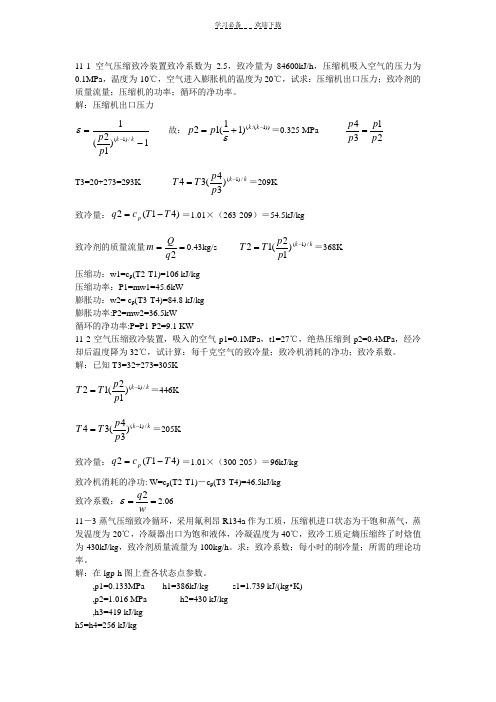
11-1空气压缩致冷装置致冷系数为2.5,致冷量为84600kJ/h ,压缩机吸入空气的压力为0.1MPa ,温度为-10℃,空气进入膨胀机的温度为20℃,试求:压缩机出口压力;致冷剂的质量流量;压缩机的功率;循环的净功率。
解:压缩机出口压力1)12(1/)1(-=-k k p p ε 故:))1/(()11(12-+=k k p p ε=0.325 MPa 2134p p p p = T3=20+273=293K k k p p T T /)1()34(34-==209K 致冷量:)41(2T T c q p -==1.01×(263-209)=54.5kJ/kg 致冷剂的质量流量==2q Q m 0.43kg/s k k p p T T /)1()12(12-==368K 压缩功:w1=c p (T2-T1)=106 kJ/kg压缩功率:P1=mw1=45.6kW膨胀功:w2= c p (T3-T4)=84.8 kJ/kg膨胀功率:P2=mw2=36.5kW循环的净功率:P=P1-P2=9.1 KW11-2空气压缩致冷装置,吸入的空气p1=0.1MPa ,t1=27℃,绝热压缩到p2=0.4MPa ,经冷却后温度降为32℃,试计算:每千克空气的致冷量;致冷机消耗的净功;致冷系数。
解:已知T3=32+273=305Kk k p p T T /)1()12(12-==446K k k p p T T /)1()34(34-==205K 致冷量:)41(2T T c q p -==1.01×(300-205)=96kJ/kg致冷机消耗的净功: W=c p (T2-T1)-c p (T3-T4)=46.5kJ/kg 致冷系数:==wq 2ε 2.06 11-3蒸气压缩致冷循环,采用氟利昂R134a 作为工质,压缩机进口状态为干饱和蒸气,蒸发温度为-20℃,冷凝器出口为饱和液体,冷凝温度为40℃,致冷工质定熵压缩终了时焓值为430kJ/kg ,致冷剂质量流量为100kg/h 。
工程热力学思考题及答案 第十一章
逆损失,由于工质性质不同,不可逆因素和不可逆程度是各不相同的,因此其热效率与工质性质有
关。
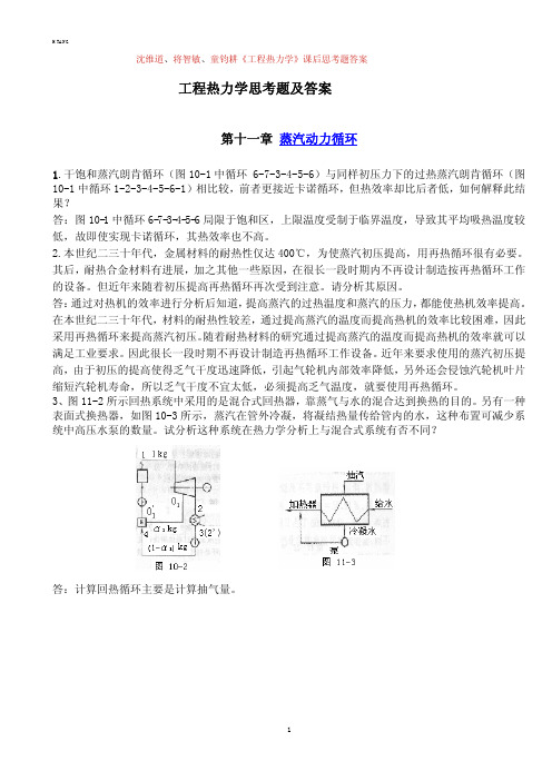
5.蒸汽动力循环中,在动力机中膨胀作功后的乏汽被排入冷凝器中,向冷却水放出大量的热量 q2, 如果将乏汽直接送入汽锅中使其再吸热变为新蒸汽,不是可以避免在冷凝器中放走大量热量,从而
减少对新汽的加热量 q1 大大提高热效率吗?这样想法对不对?为什么? 答:这样的想法是不对的。因为从热力学第二定律来讲一个非自发过程的进行必定要有一个自发过
承受较高燃气温度,燃气温度通常可高达 1800-2300K,而蒸汽循环蒸汽过热器外面是高温燃气里 面是蒸汽,所以过热器壁面温度必定高于蒸汽温度,这与柴油机是不同的,蒸汽循环的最高蒸汽温
度很少超过 600K.。因此蒸汽循环的热效率较低。
2
H TANG
7.应用热泵来供给中等温度(例如 100℃上下)的热量是比直接利用高温热源的热量来得济,因此有 人设想将乏汽在冷凝器中放出热量的一部分用热泵提高温度,用以加热低温段(100℃以下)的锅炉 给水,这样虽然需要增添热泵设备。但却可以取消低温段的抽汽回热,使抽汽回热设备得以简化, 而对循环热效率也能有所补益。这样的想法在理论上是否正确? 答:这种想法是不正确的。回热循环是是通过减少了温差传热不可逆因素,从而使热效率提高,使 该循环向卡诺循环靠近了一步。而该题中的想法恰恰是又增加了 温差传热不可逆因素。因此对效 率提高是没有好处的。 8.热量利用系数ξ 说明了全部热量的利用程度,为什么又说它不能完善地衡量循环的经济性? 答:热量利用系数说明了全部热量的利用程度,但是不能完善的衡量循环的经济性。能量分为可用 能与不可用能,能量的品位是不同的。在实际工程应用中用的是可用能。可用能在各个部分各个过 程的损失是不能用热量利用系数来说明的。 9.总结一下气体动力循环和蒸汽动力循环提高循环热效率的共同原则。 答:提高循环热效率的共同原则是:提高工质的平均吸热温度。
工程热力学第三版电子教案第11章自我测验题

第十一章自我测验题1、298K,101300Pa时有下列放热反应,指明反应热效应中哪些可称为标准生成焓(l);(2);(3);(4)o2、反应的热效应Qp>0,达平衡时,问下列情况下平衡是否被破坏?Kp是否变化?反应向何方向进行?(1)增加压力;(2)减少二氧化氮的分压力;(3)增加氧气的分压力;(4)升温;(5)增加二氧化氮的浓度;(6)加人催化剂。
3、某一反应的标准吉布斯函数变化大于0,能否说明该反应不能自发进行?为什么?4、碳的气化反应,试问:(1)达平衡时有人说,有人则说,究竟哪个对?(2)这时,,还是?5、确定气态丁烷在298K和101325Pa下的定压燃烧反应热效应。
假定生成物中的水为液相,且各物质的标准生成焓为:,,。
6、求下列反应在101300Pa及600K下的热效应已知有关参数及各气体的摩尔热容为:,7、计算丙烷在过量空气量为20%下完全燃烧时的空气燃料比。
空气中氮、氧的物质的量之比为3.76。
已知丙烷在空气量为理论值时完全燃烧的方程为:8、丙烷燃烧后的干燃气摩尔分数为:二氧化碳11.5%,氧气2.7%,一氧化碳0.7%,氮气85.1%。
试确定空燃比,过量空气系数,并写出此反应方程。
9、在101300Pa下测得四氧化二氮在60℃时有50%离解成二氧化氮,计算反应的K p10、已知气相反应,在某温度时的平衡常数为29,求同一温度下:(1)反应的平衡常数;(2)反应的平衡常数。
11、在1立方分米的容器内应放入多少mol的PCl5才可得到100mol的Cl2?已知在250℃时的平衡常数为1.78。
第十一章自测题答案1、反应(2)的反应热效应为二氧化碳的标准生成焓反应(4)的反应热效应为水蒸气的标准生成焓2、(1)平衡被破坏,Kp不变,反应向正方向进行;(2)平衡被破坏,Kp不变,反应向正方向进行;(3)平衡被破坏,Kp不变,反应向正方向进行;(4)平衡被破坏,Kp增大,反应向正方向进行;(5)平衡被破坏,Kp不变,反应向反方向进行;(6)平衡被破坏,Kp增大,反应向正方向进行;3、不能。
工程热力学高教第三版课后习题第十一章答案
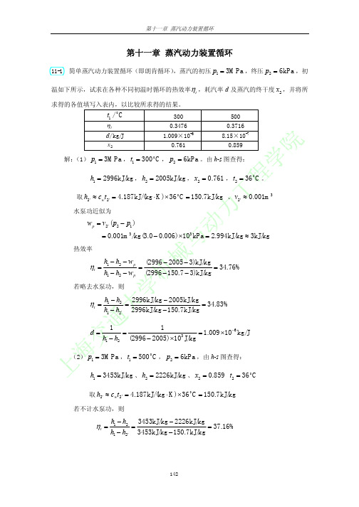
(2) p1 = 3MPa , t1 = 500 C , p2 = 6kPa ,由 h-s 图查得:
h1 = 3453kJ/kg 、 h2 = 2226kJ/kg 、 x2 = 0.859 t2 = 36 o C
取 h2′ ≈ cwt2' = 4.187kJ/(kg ⋅ K) × 36 C = 150.7kJ/kg
o
若不计水泵功,则
ηt =
h1 − h2 3453kJ/kg − 2226kJ/kg = = 37.16% h1 − h2′ 3453kJ/kg − 150.7kJ/kg
142
第十一章 蒸汽动力装置循环
d=
1 1 = = 8.15 × 10⁻⁷ kg/J 3 h1 − h2 (3453 − 2226) × 10 J/kg
热效率
ηt =
h1 − h2 − wp h1 − h2 − wp
=
(2996 − 2005 − 3)kJ/kg = 34.76% (2996 − 150.7 − 3)kJ/kg
若略去水泵功,则
ηt =
d=
h1 − h2 2996kJ/kg − 2005kJ/kg = = 34.83% h1 − h2′ 2996kJ/kg − 150.7kJ/kg 1 1 = = 1.009 × 10⁻⁶ kg/J 3 h1 − h2 (2996 − 2005) ×10 J/kg
143
第十一章 蒸汽动力装置循环
解: (1)由 p1 = 12.0MPa 、 t1 = 450 o C 及再热压力 pb = 2.4MPa ,由 h-s 图查得
h1 = 3212kJ/kg、s1 = 6.302kJ/(kg ⋅ K)、hb = 2819kJ/kg 、 ha = 3243kJ/kg 、 h2 = 2116kJ/kg 、 x 2 = 0.820 p2 = 0.004MPa 、 s1 = sc = sb = 6.302kJ/(kg ⋅ K) , sc ' = 0.4221kJ/(kg ⋅ K) 、 sc " = 8.4725kJ/(kg ⋅ K)
工程热力学思考题答案,第十一章

第十一章 制冷循环1、家用冰箱的使用说明书上指出,冰箱应放置在通风处,并距墙壁适当距离,以及不要把冰箱温度设置过低,为什么?答:为了维持冰箱的低温,需要将热量不断地传输到高温热源(环境大气),如果冰箱传输到环境大气中的热量不能及时散去,会使高温热源温度升高,从而使制冷系数降低,所以为了维持较低的稳定的高温热源温度,应将冰箱放置在通风处,并距墙壁适当距离。
在一定环境温度下,冷库温度愈低,制冷系数愈小,因此为取得良好的经济效益,没有必要把冷库的温度定的超乎需要的低。
2、为什么压缩空气制冷循环不采用逆向卡诺循环?答:由于空气定温加热与定温放热不易实现,故不能按逆向卡诺循环运行。
在压缩空气制冷循环中,用两个定压过程来代替逆向卡诺循环的两个定温过程。
3、压缩蒸气制冷循环采用节流阀来代替膨胀机,压缩空气制冷循环就是否也可以采用这种方法?为什么?答:压缩空气制冷循环不能采用节流阀来代替膨胀机。
工质在节流阀中的过程就是不可逆绝热过程,不可逆绝热节流熵增大,所以不但减少了制冷量也损失了可逆绝热膨胀可以带来的功量。
而压缩蒸气制冷循环在膨胀过程中,因为工质的干度很小,所以能得到的膨胀功也极小。
而增加一台膨胀机,既增加了系统的投资,又降低了系统工作的可靠性。
因此,为了装置的简化及运行的可靠性等实际原因采用节流阀作绝热节流。
4、压缩空气制冷循环的制冷系数、循环压缩比、循环制冷量三者之间的关系如何?答:压缩空气制冷循环的制冷系数为:()()142314-----o o net k o q q h h w q q h h h h ε===(a) (b) 压缩空气制冷循环状态参数图空气视为理想气体,且比热容为定值,则:()()142314T T T T T T ε-=--- 循环压缩比为:21p p π=过程1-2与3-4都就是定熵过程,因而有:1322114k k T T P T P T -⎛⎫== ⎪⎝⎭ 代入制冷系数表达式可得:111k k επ-=- 由此式可知,制冷系数与增压比有关。
工程热力学第三版答案【英文】第10章

10-8Heat rejected decreases; everything else increases.The pump work remains the same, the moisture content decreases, everything else increases.The boiler exit pressure will be (a) lower than the boiler inlet pressure in actual cycles, and (b) the same as the boiler inlet pressure in ideal cycles.10-16A simple ideal Rankine cycle with water as the working fluid operates between the specified pressure limits. The rates of heat addition and rejection, and the thermal efficiency of the cycle are to be determined.Assumptions 1 Steady operating conditions exist. 2 Kinetic and potential energy changes are negligible.Analysis From the steam tables (Tables A-4E, A-5E, and A-6E),Btu/lbm81.11140.240.109Btu/lbm40.2ft psia 5.404Btu 1 psia )3800)(/lbm ft 01630.0()(/lbmft 01630.0Btu/lbm40.109in p,1233121in p,3psia 3 @1psia 3 @1=+=+==⎪⎪⎭⎫⎝⎛⋅-=-=====w h h P P w h h f f v v vBtu/lbm 24.975)8.1012)(8549.0(40.1098549.06849.12009.06413.1 psia 3RBtu/lbm 6413.1Btu/lbm0.1456F 900psia 80044443443333=+=+==-=-=⎭⎬⎫==⋅==⎭⎬⎫︒==fgf fg fh x h h s s s x s s P s h T PKnowing the power output from the turbine the mass flow rate of steam in the cycle is determined fromlbm/s 450.3kJ 1Btu 0.94782)Btu/lbm 24.975(1456.0kJ/s 1750)(43out T,43out T,=⎪⎭⎫ ⎝⎛-=-=−→−-=h h W m h h m WThe rates of heat addition and rejection areBtu/s2987Btu/s 4637=-=-==-=-=Btu/lbm )40.109.24lbm/s)(975 450.3()(Btu/lbm )81.1110.6lbm/s)(145 450.3()(14out 23inh h m Q h h m Qand the thermal efficiency of the cycle is35.6%==-=-=3559.04637298711inout thQ Q η10-24A single-flash geothermal power plant uses hot geothermal water at 230ºC as the heatsource. The mass flow rate of steam through the turbine, the isentropic efficiency of the turbine, the power output from the turbine, and the thermal efficiency of the plant are to be determined.Assumptions 1 Steady operating conditions exist. 2 Kinetic and potential energy changes are negligible.Analysis (a ) We use properties of water for geothermal water (Tables A-4 through A-6)kJ/kg 14.990kP a 500 14.9900C 23022122111=-=⎭⎬⎫====⎭⎬⎫=︒=fg f h h h x h h P h x T The mass flow rate of steam through the turbine is===kg/s) 230)(1661.0(123m x m (b ) Turbine:kJ/kg 7.2344)1.2392)(90.0(81.19190.0kPa 10kJ/kg 3.2160kPa 10K kJ/kg 8207.6kJ/kg1.27481kPa 500444443443333=+=+=⎭⎬⎫===⎭⎬⎫==⋅==⎭⎬⎫==fg f s h x h h x P h s s P s h x P0.686=--=--=3.21601.27487.23441.27484343s T h h h h η (c ) The power output from the turbine iskW 15,410=-=-=kJ/kg )7.23448.1kJ/kg)(274 38.20()(433out T,h h mW (d ) We use saturated liquid state at the standard temperature for dead state enthalpykJ/kg 83.1040C 25000=⎭⎬⎫=︒=h x TkW 622,203kJ/kg )83.104.14kJ/kg)(990 230()(011in=-=-=h h m E7.6%====0.0757622,203410,15inout T,thE W η10-36An ideal reheat Rankine with water as the working fluid is considered. The temperatures at the inlet of both turbines, and the thermal efficiency of the cycle are to be determined. Assumptions 1 Steady operating conditions exist. 2 Kinetic and potential energy changes are negligible.Analysis From the steam tables (Tables A-4, A-5, and A-6),kJ/kg87.19806.781.191kJ/kg06.7m kPa 1kJ 1 kPa )107000)(/kg m 001010.0()(/kgm 001010.0kJ/kg81.191in p,1233121in p,3kPa 10 @1kPa 10 @1=+=+==⎪⎭⎫ ⎝⎛⋅-=-=====w h h P P w h h f f v v vC373.3︒==⎭⎬⎫==⋅=+=+==+=+=⎭⎬⎫==33433444444kJ/kg5.3085kP a 7000K kJ/kg 3385.6)6160.4)(93.0(0457.2kJ/kg0.2625)5.2047)(93.0(87.720 93.0kP a 800T h s s P s x s s h x h h x P fg f fg fC416.2︒==⎭⎬⎫==⋅=+=+==+=+=⎭⎬⎫==55655666666kJ/kg0.3302kP a 800K kJ/kg 6239.7)4996.7)(93.0(6492.0kJ/kg 4.2416)1.2392)(93.0(81.191 90.0kP a 10T h s s P s x s s h x h h x P fg f fg fThus, kJ/kg6.222481.1914.2416kJ/kg 6.35630.26250.330287.1985.3085)()(16out 4523in =-=-==-+-=-+-=h h q h h h h qand37.6%==-=-=3757.06.35636.222411in out th q q η10-38A steam power plant that operates on a reheat Rankine cycle is considered. The condenser pressure, the net power output, and the thermal efficiency are to be determined.Assumptions 1 Steady operating conditions exist. 2 Kinetic and potential energy changes are negligible.Analysis (a()()()()()()3)(Eq. 2.335885.02.33582) (Eq. ?1) (Eq.95.0?K kJ/kg 2815.7kJ/kg2.3358C 450 MP a 2kJ/kg3.30271.29485.347685.05.3476kJ/kg 1.2948MP a 2K kJ/kg 6317.6kJ/kg5.3476C 550 MP a 5.12665566565656666655554334434343443333s s T sT s s T sT s s h h h h h h h h h h s s P h x P s h T P h h h h h h h h h s s P s h T P --=--=−→−--==⎭⎬⎫===⎭⎬⎫==⋅==⎭⎬⎫︒===--=--=→--==⎭⎬⎫==⋅==⎭⎬⎫︒==ηηηη The pressure at state 6 may be determined by a trial-error approach from the steam tables or by using EES from the above three equations:P 6 = 9.73 kPa , h 6 = 2463.3 kJ/kg,(b ) Then,()()()()kJ/kg59.20302.1457.189kJ/kg14.020.90/m kP a 1kJ 1kP a 73.912,500/kg m 0.00101//kgm 001010.0kJ/kg57.189in ,123121in ,3kPa 10 @1kPa 73.9 @1=+=+==⎪⎪⎭⎫⎝⎛⋅-=-=====p pp f f w h h P P w h h ηv v v Cycle analysis:()()kW 10,242==-==-=-==-+-=-+-=kg 2273.7)kJ/-.8kg/s)(3603 7.7()(kJ/kg7.227357.1893.2463kJ/kg 8.36033.24632.335859.2035.3476out in net16out 4523in q q m W h h q h h h h q (c ) The thermal efficiency is36.9%==-=-=369.0kJ/kg3603.8kJ/kg2273.711in out th q q η。
工程热力学第三版答案【英文】第9章

9-13The three processes of an air-standard cycle are described. The cycle is to be shown on the P-v and T-s diagrams, and the back work ratio and the thermal efficiency are to be determined.Assumptions 1 The air-standard assumptions are applicable. 2 Kinetic and potential energy changes are negligible. 3 Air is an ideal gas with constant specific heats. Properties The properties of air are given as R = 0.287 kJ/kg.K, c p = 1.005 kJ/kg.K, c v = 0.718 kJ/kg·K, and k = 1.4.Analysis (a) The P -v and T -s diagrams of the cycle are shown in the figures. (b) The temperature at state 2 is K 2100kP a100kP a 700K) 300(1212===P P T TK 210023==T TDuring process 1-3, we havekJ/kg516.600)K 21K)(300kJ/kg 287.0()()(3131113,13=-⋅-=--=--=-=⎰-T T R P Pd w in V V vDuring process 2-3, we havekJ/kg8.1172n7K)(2100)Kl kJ/kg 287.0(7ln 7ln ln22233232,32=⋅======⎰⎰-RT RT RT d RTPd w out V VV V v Vv The back work ratio is then0.440===--kJ/kg8.1172kJ/kg6.516,32,13outin bw w w rHeat input is determined from an energybalance on the cycle during process 1-3,kJ/kg2465kJ/kg 1172.8300)K)(2100kJ/kg 718.0()(,3213,3231,3131,32,31=+-⋅=+-=+∆=-∆=--------outv outin out in w T T c w u q u w qThe net work output issvkJ/kg 2.6566.5168.1172,13,32=-=-=--in out net w w w(c) The thermal efficiency is then26.6%====266.0kJ2465kJ656.2in net th q w η9-21An air-standard cycle executed in a piston-cylinder system is composed of threespecified processes. The cycle is to be sketcehed on the P -v and T -s diagrams; the heat and work interactions and the thermal efficiency of the cycle are to bedetermined; and an expression for thermal efficiency as functions of compression ratio and specific heat ratio is to be obtained.Assumptions 1 The air-standard assumptions are applicable. 2 Kinetic and potential energy changes are negligible. 3 Air is an ideal gas with constant specific heats. Properties The properties of air are given as R = 0.3 kJ/kg·K and c v = 0.3 kJ/kg·K. Analysis (a) The P -v and T -s diagrams of the cycle are shown in the figures. (b) Noting that1.4297.00.1KkJ/kg 0.13.07.0===⋅=+=+=vv c c k R c c p pProcess 1-2: Isentropic compressionK 4.584)5)(K 293(429.01112112===⎪⎪⎭⎫ ⎝⎛=--k k r T T T vvkJ/kg 204.0=-⋅=-=-K )2934.584)(K kJ/kg 7.0()(12in 2,1T T c w v0=-21qFrom ideal gas relation,2922)5)(4.584(3212323==−→−===T r T T v v v v Process 2-3: Constant pressure heat additionkJ/kg701.3=-⋅=-=-==⎰-K )4.5842922)(K kJ/kg 3.0()()(2323232out 3,2T T R P Pd w v v vskJ/kg2338=-⋅=-=∆=∆+=----K )4.5842922)(K kJ/kg 1()(233232,32in 3,2T T c h u w q p outProcess 3-1: Constant volume heat rejectionkJ/kg 1840.3=⋅=-=∆=--K 293)-K)(2922kJ/kg 7.0()(1331out 1,3T T c u q v0=-13w(c) Net work isK kJ/kg 3.4970.2043.701in 2,1out 3,2net ⋅=-=-=--w w wThe thermal efficiency is then21.3%====213.0kJ2338kJ497.3in net th q w η9-32The two isentropic processes in an Otto cycle are replaced with polytropic processes.The heat added to and rejected from this cycle, and the cycle’s thermal efficiency are to be determined.Assumptions 1 The air-standard assumptions are applicable. 2 Kinetic and potential energy changes are negligible. 3 Air is an ideal gas with constant specific heats. Properties The properties of air at room temperature are R = 0.287 kPa·m 3/kg·K, c p = 1.005 kJ/kg·K, c v = 0.718 kJ/kg·K, and k = 1.4 (Table A-2a). Analysis The temperature at the end of the compression isK 4.537K)(8) 288(13.11112112===⎪⎪⎭⎫ ⎝⎛=---n n r T T T vvAnd the temperature at the end of the expansion isK 4.78981K) 1473(113.11314334=⎪⎭⎫⎝⎛=⎪⎭⎫ ⎝⎛=⎪⎪⎭⎫ ⎝⎛=---n n r T T T vvThe integral of the work expression for the polytropic compression giveskJ/kg 6.238)18(13.1K) K)(288kJ/kg 287.0(1113.1121121=--⋅=⎥⎥⎦⎤⎢⎢⎣⎡-⎪⎪⎭⎫ ⎝⎛-=---n n RT w vvSimilarly, the work produced during the expansion iskJ/kg 0.65418113.1K) K)(1473kJ/kg 287.0(1113.1143343=⎥⎥⎦⎤⎢⎢⎣⎡-⎪⎭⎫⎝⎛-⋅-=⎥⎥⎦⎤⎢⎢⎣⎡-⎪⎪⎭⎫ ⎝⎛--=---n n RT w vv Application of the first law to each of the four processes giveskJ/kg 53.59K )2884.537)(K kJ/kg 718.0(kJ/kg 6.238)(122121=-⋅-=--=--T T c w q v kJ/kg 8.671K )4.5371473)(K kJ/kg 718.0()(2332=-⋅=-=-T T c q vkJ/kg 2.163K )4.7891473)(K kJ/kg 718.0(kJ/kg 0.654)(434343=-⋅-=--=--T T c w q vkJ/kg 0.360K )2884.789)(K kJ/kg 718.0()(1414=-⋅=-=-T T c q vThe head added and rejected from the cycle arekJ/kg419.5kJ/kg 835.0=+=+==+=+=----0.36053.592.1638.6711421out 4332in q q q q q qThe thermal efficiency of this cycle is then0.498=-=-=0.8355.41911in out th q q η9-37An ideal Otto cycle with air as the working fluid has a compression ratio of 8. Theamount of heat transferred to the air during the heat addition process, the thermal efficiency, and the thermal efficiency of a Carnot cycle operating between the same temperature limits are to be determined. Assumptions 1 The air-standard assumptions are applicable. 2 Kinetic and potential energy changes are negligible. 3 Air is an ideal gas with variable specific heats.Properties The properties of air are given in Table A-17E. Analysis (a) Process 1-2: isentropic compression.32.144Btu/lbm92.04R 540111==−→−=r u T v()Btu/lbm 11.28204.1832.144811212222=−→−====u r r r r v v v v v Process 2-3: v = constant heat addition.Btu/lbm241.42=-=-===−→−=28.21170.452419.2Btu/lbm452.70R 240023333u u q u T in r vvP(b) Process 3-4: isentropic expansion.()()Btu/lbm 205.5435.19419.28434334=−→−====u r r r r v v v v v Process 4-1: v = constant heat rejection.Btu/lbm 50.11304.9254.20514out =-=-=u u q53.0%=-=-=Btu/lbm241.42Btu/lbm113.5011in out th q q η (c) The thermal efficiency of a Carnot cycle operating between the same temperature limits is 77.5%=-=-=R2400R54011C th,H L T T η9-40The expressions for the maximum gas temperature and pressure of an ideal Otto cycleare to be determined when the compression ratio is doubled.Assumptions 1 The air-standard assumptions are applicable. 2 Kinetic and potential energy changes are negligible. 3 Air is an ideal gas with constant specific heats. Analysis The temperature at the end of the compression varies with the compression ratio as1112112--=⎪⎪⎭⎫⎝⎛=k k r T T T v vsince T 1 is fixed. The temperature rise during thecombustion remains constant since the amount of heat addition is fixed. Then, the maximum cycle temperature is given by11in 2in 3//-+=+=k r T c q T c q T v vThe smallest gas specific volume during the cycle isr13v v =When this is combined with the maximum temperature, the maximum pressure is given by ()11in 1333/-+==k r T c qRrRT P v v v9-47An ideal diesel cycle has a compression ratio of 20 and a cutoff ratio of 1.3. The maximum temperature of the air and the rate of heat addition are to be determined. Assumptions 1 The air-standard assumptions are applicable. 2 Kinetic and potential energy changes are negligible. 3 Air is an ideal gas with constant specific heats. Properties The properties of air at room temperature are c p = 1.005 kJ/kg·K, c v = 0.718 kJ/kg·K, R = 0.287 kJ/kg·K, and k = 1.4 (Table A-2a). Analysis()K 6.95420K) 288(14.11112112===⎪⎪⎭⎫ ⎝⎛=---k k r T T T vvK 1241===⎪⎪⎭⎫ ⎝⎛=K)(1.3) 6.954(22323c r T T T vv Combining the first law as applied to the various processes with the process equations gives6812.0)13.1(4.113.12011)1(1114.111.41th =---=---=--c k c k r k r r ηAccording to the definition of the thermal efficiency,kW 367===0.6812kW 250th net inηW Q9-59An ideal dual cycle has a compression ratio of 15 and cutoff ratio of 1.4. The net work,heat addition, and the thermal efficiency are to be determined.Assumptions 1 The air-standard assumptions are applicable. 2 Kinetic and potential energy changes are negligible. 3 Air is an ideal gas with constant specific heats. Properties The properties of air at room temperature are R = 0.3704 psia·ft 3/lbm.R (Table A-1E), c p = 0.240 Btu/lbm·R, c v = 0.171 Btu/lbm·R, and k = 1.4 (Table A-2Ea).Analysis Working around the cycle, the germane properties at the various states are()R 158015R) 535(14.11112112===⎪⎪⎭⎫ ⎝⎛=---k k r T T T vvout()psia 2.62915psia) 2.14(4.112112===⎪⎪⎭⎫ ⎝⎛=k kr P P P vvpsia 1.692psia) 2.629)(1.1(23====P r P P p xR 1738psia 629.2psia 692.1R) 1580(22=⎪⎪⎭⎫ ⎝⎛=⎪⎪⎭⎫ ⎝⎛=PP T T xxR 2433R)(1.4) 1738(33===⎪⎪⎭⎫⎝⎛=c x xx r T T T vvR 2.942151.4R) 2433(14.11314334=⎪⎭⎫⎝⎛=⎪⎪⎭⎫ ⎝⎛=⎪⎪⎭⎫ ⎝⎛=---k c k rr T T T vvApplying the first law to each of the processes givesBtu/lbm 7.178R )5351580)(R Btu/lbm 171.0()(1221=-⋅=-=-T T c w v Btu/lbm 02.27R )15801738)(R Btu/lbm 171.0()(22=-⋅=-=-T T c q x x vBtu/lbm 8.166R )17382433)(R Btu/lbm 240.0()(33=-⋅=-=-x p x T T c qB t u /l b 96.47R )17382433)(R Btu/lbm 171.0(Btu/lbm 8.166)(333=-⋅-=--=--x x x T T c q w vBtu/lbm 9.254R )2.9422433)(R Btu/lbm 171.0()(4343=-⋅=-=-T T c w vThe net work of the cycle isBtu/lbm 124.2=-+=-+=---7.17896.479.25421343net w w w w x and the net heat addition isBtu/lbm 193.8=+=+=--8.16602.2732in x x q q q Hence, the thermal efficiency is0.641===Btu/lbm193.8Btu/lbm124.2in net th q w η9-61An expression for cutoff ratio of an ideal diesel cycle is to be developed.Assumptions 1 The air-standard assumptions are applicable. 2 Kinetic and potentialenergy changes are negligible. 3 Air is an ideal gas with constant specific heats. Analysis Employing the isentropic process equations,112-=k rT Toutwhile the ideal gas law gives1123T r r r T T k c c -==When the first law and the closed system work integral is applied to the constant pressure heat addition, the result is)()(111123in T r T r r c T T c q k k c p p ---=-=When this is solved for cutoff ratio, the result is11in1T r c q r k p c -+=9-81A simple ideal Brayton cycle with air as the working fluid has a pressure ratio of 10. The air temperature at the compressor exit, the back work ratio, and the thermal efficiency are to be determined.Assumptions 1 Steady operating conditions exist. 2 The air-standard assumptions are applicable. 3 Kinetic and potential energy changes are negligible. 4 Air is an ideal gas with variable specific heats.Properties The properties of air are given in Table A-17E. Analysis (a ) Noting that process 1-2 is isentropic,T h P r 11112147=−→−==520R124.27Btu /lbm .()()Btu/lbm 240.11 147.122147.110221212==−→−===h T P P P P r r R 996.5(b ) Process 3-4 is isentropic, and thus()Btu/lbm38.88283.26571.504Btu/lbm115.8427.12411.240Btu/lbm 265.834.170.1741010.174Btu/lbm 504.71R 200043out T,12inC,43433343=-=-==-=-==−→−=⎪⎭⎫⎝⎛====−→−=h h w h h w h P P P P P h T r r rThen the back-work ratio becomess200052048.5%===Btu/lbm238.88Btu/lbm115.84outT,in C,bw w w r(c ) 46.5%====-=-==-=-=Btu/lbm264.60Btu/lbm123.04Btu/lbm123.0484.11588.238Btu/lbm264.6011.24071.504inout net,th in C,out T,out net,23in q w w w w h h q η9-87A simple ideal Brayton cycle with air as the working fluid has a pressure ratio of 10.The air temperature at the compressor exit, the back work ratio, and the thermal efficiency are to be determined.Assumptions 1 Steady operating conditions exist. 2 The air-standard assumptions are applicable. 3 Kinetic and potential energy changes are negligible. 4 Air is an ideal gas with variable specific heats.Properties The properties of air are given in Table A-17E. Analysis (a ) Noting that process 1-2 is isentropic,T h P r 11112147=−→−==520R124.27Btu /lbm .()()Btu/lbm 240.11 147.122147.110221212==−→−===h T P P P P r r R 996.5(b ) Process 3-4 is isentropic, and thus()Btu/lbm38.88283.26571.504Btu/lbm115.8427.12411.240Btu/lbm 265.834.170.1741010.174Btu/lbm 504.71R 200043out T,12inC,43433343=-=-==-=-==−→−=⎪⎭⎫⎝⎛====−→−=h h w h h w h P P P P P h T r r rThen the back-work ratio becomes48.5%===Btu/lbm238.88Btu/lbm115.84outT,in C,bw w w rs2000520(c ) 46.5%====-=-==-=-=Btu/lbm264.60Btu/lbm123.04Btu/lbm123.0484.11588.238Btu/lbm264.6011.24071.504inout net,th in C,out T,out net,23in q w w w w h h q η(d) The expression for the cycle thermal efficiency is obtained as follows:⎪⎭⎫ ⎝⎛---⎪⎭⎫ ⎝⎛-=⎪⎭⎫⎝⎛---=⎪⎪⎭⎫ ⎝⎛---=-⎪⎪⎭⎫ ⎝⎛--=---=----=-==-----------1111111111111111111231223in in 2,1out 3,2in net th 11)1(11111)1(11)1(1)1(1)()()()()(k k p k p k p k k v p k k p k v p p v r r k k r r k c R r T T r k c R r r T c r T T r T c c R r T r rT c T r T c c RT T c T T c T T R q w w q w η since 111kc c c c c c R p v p v p p -=-=-=。
- 1、下载文档前请自行甄别文档内容的完整性,平台不提供额外的编辑、内容补充、找答案等附加服务。
- 2、"仅部分预览"的文档,不可在线预览部分如存在完整性等问题,可反馈申请退款(可完整预览的文档不适用该条件!)。
- 3、如文档侵犯您的权益,请联系客服反馈,我们会尽快为您处理(人工客服工作时间:9:00-18:30)。
11-13An ideal vapor-compression refrigeration cycle with refrigerant-134a as the working fluid is considered. The rate of heat removal from the refrigerated space, the power input to the compressor, the rate of heat rejection to the environment, and the COP are to be determined.Assumptions 1 Steady operating conditions exist. 2 Kinetic and potential energy changes are negligible.Analysis (a ) In an ideal vapor-compression refrigeration cycle, the compression process is isentropic, the refrigerant enters the compressor as a saturated vapor at the evaporator pressure, and leaves the condenser as saturated liquid at the condenser pressure. From the refrigerant tables (Tables A-12 and A-13),()()throttlingkJ/kg 82.88kJ/kg82.88liquid sat.MP a 7.0C 95.34kJ/kg 50.273MP a 7.0K kJ/kg 94779.0kJ/kg97.236 vapor sat.kP a 12034MPa 7.0 @ 3322122kPa 120 @ 1kPa 120 @ 11=≅==⎭⎬⎫=︒==⎭⎬⎫==⋅====⎭⎬⎫=h h h h P T h s s P s s h h P f g gThen the rate of heat removal from therefrigerated space and the power input to the compressor are determined fromand()()()()()()kW 1.83kW 7.41=-=-==-=-=kJ/kg 236.97273.50kg/s 0.05kJ/kg 82.8897.236kg/s 0.0512in41h h m W h h m Q L(b ) The rate of heat rejection to the environment is determined fromkW 9.23=+=+=83.141.7inW Q Q L H (c ) The COP of the refrigerator is determined from its definition,4.06===kW 1.83kW7.41COP inR W Q L11-15An ideal vapor-compression refrigeration cycle with refrigerant-134a as the working fluid is considered. The throttling valve in the cycle is replaced by an isentropic turbine. The percentage increase in the COP and in the rate of heat removal from the refrigerated space due to this replacement are to be determined.sAssumptions 1 Steady operating conditions exist. 2 Kinetic and potential energy changes are negligible.Analysis If the throttling valve in the previous problem is replaced by an isentropic turbine, we would have s 4s = s 3 = s f @ 0.7 MPa = 0.33230 kJ/kg·K and the enthalpy at the turbine exit would be()()()kJ/kg58.8248.2142802.049.222802.085503.009275.033230.0kPa120 @44kPa120 @34=+=+==-=⎪⎪⎭⎫⎝⎛-=fgs f s fg fs h x h h s s s xThen,()()()kW 7.72kJ/kg 82.58236.97kg/s 0.0541=-=-=s Lh h m Q and23.4kW 1.83kW 7.72COP inR ===W Q LThen the percentage increase in Qand COP becomes4.2%4.2%=-=∆==-=∆=06.406.423.4COP COP COP in Increase 41.741.772.7in Increase R R R L L L Q Q Q11-23A vapor-compression refrigeration cycle with refrigerant-134a as the working fluid isconsidered. The amount of cooling, the work input, and the COP are to bedetermined. Also, the same parameters are to be determined if the cycle operated on the ideal vapor-compression refrigeration cycle between the same temperature limits. Assumptions 1 Steady operating conditions exist. 2 Kinetic and potential energy changes are negligible. Analysis (a) The expansion process through the expansionsvalve is isenthalpic: h 4 = h 3. Then,kJ/kg 159.3=-=-=19.24349.40241h h q L kJ/kg 8.21019.24300.45432=-=-=h h q H kJ/kg 51.51=-=-=49.40200.45412in h h w3.093===kJ/kg51.51kJ/kg3.159COP in w q L (c) Ideal vapor-compression refrigeration cycle solution:kJ/kg 149.2=-=-=80.24904.39941h h q LkJ/kg 190.980.24971.44032=-=-=h h q H kJ/kg 41.67=-=-=04.39971.44012in h h w3.582===kJ/kg67.41kJ/kg 2.149COP in w q LDiscussion In the ideal operation, the refrigeration load decreases by 6.3% and the work input by 19.1% while the COP increases by 15.8%.11-75A regenerative gas refrigeration cycle using air as the working fluid is considered. The effectiveness of the regenerator, the rate of heat removal from the refrigerated space, the COP of the cycle, and the refrigeration load and the COP if this system operated on the simple gas refrigeration cycle are to be determined.Assumptions 1 Steady operating conditions exist. 2 Kinetic and potential energy changes are negligible. 3 Air is an ideal gas with constant specific heats.Properties The properties of air at room temperature are c p = 1.005 kJ/kg·K and k = 1.4 (Table A-2).Analysis (a ) From the isentropic relations, ()()()K 4.4325K 2.2734.1/4.0k/1k 1212==⎪⎪⎭⎫ ⎝⎛=-PP T T sK5.4722.2732.2734.43280.02212121212=−→−--=--=--=T T T T TT h h h h s s C ηThe temperature at state 4 can be determined by solvingsthe following two equations simultaneously:()4.1/4.04k/1k 454551⎪⎭⎫ ⎝⎛=⎪⎪⎭⎫ ⎝⎛=-T PP T T sss T T T T h h h h 54454542.19385.0--=→--=ηUsing EES, we obtain T 4 = 281.3 K.An energy balance on the regenerator may be written asor,()()K3.2463.2812.3082.273431661436143=+-=+-=-=-−→−-=-T T T T T T T T T T c m T T c m p pThe effectiveness of the regenerator is0.434=--=--=--=3.2462.3083.2812.30863436343regen T T T T h h h h ε (b ) The refrigeration load iskW 21.36=-=-=K )2.19346.3kJ/kg.K)(2 5kg/s)(1.00 4.0()(56T T c m Q p L(c ) The turbine and compressor powers and the COP of the cycle are kW 13.80K )2.27372.5kJ/kg.K)(4 5kg/s)(1.00 4.0()(12in C,=-=-=T T c mW p kW 43.35kJ/kg )2.19381.3kJ/kg.K)(2 5kg/s)(1.00 4.0()(54out T,=-=-=T T c m W p0.478=-=-==43.3513.8036.21COP outT,in C,innet,W W Q WQ LL0︒C35︒-80︒(d ) The simple gas refrigeration cycle analysis is as follows:()()K 6.19451K 2.30814.1/4.0k/1k 34=⎪⎭⎫⎝⎛=⎪⎭⎫ ⎝⎛=-r T T sK6.2116.1942.3082.30885.0444343=−→−--=−→−--=T T T T T T s T η kW24.74=-=-=kJ/kg )6.21173.2kJ/kg.K)(2 5kg/s)(1.00 4.0()(41T T c m Q p L[]kW32.41kJ/kg )6.211(308.2)2.273(472.5kJ/kg.K)5kg/s)(1.00 4.0()()(4312in net,=---=---=T T c m T T c mW p p 0.599===32.4174.24COP innet,WQ Ls35︒。