IME08电感式接近传感器选型手册(中文版)
电感式接近开关传感器的选型及使用、调试方法

电感式接近开关传感器的选型及使用、调试方法
电感式接近开关是一种常用的非接触式传感器,可以实现对金属物体的接近检测。
以下是选型和使用、调试方法的一些建议:
1. 选型:
需要确定需要检测的物体是金属还是非金属,因为电感式接近开关只能检测金属物体。
根据需要检测的物体的特性,确定需要的探测距离。
一般来说,探测距离越大,传感器的价格也会越高。
根据工作环境的特点,选择适合的传感器外壳材料,如塑料或不锈钢等。
2. 使用:
安装传感器时,需要保持传感器与物体之间的适当距离,通常由传感器的技术参数给出。
注册信号输出的方式(通常是开关型信号或模拟信号),并根据需要连接相应的电路和设备。
当物体靠近传感器时,传感器会产生一个信号,激活相应的设备。
3. 调试方法:
使用万用表或示波器等工具,检查传感器的供电电压是否正常,并确保传感器的电气连接正确无误。
逐渐调整传感器与物体之间的距离,观察传感器的信号变化,确保距离调整在合适的范围内。
如果传感器的探测距离无法满足要求,可以尝试更换探测距离更长的传感器。
如果传感器的信号不稳定或误触发,可以尝试增加滤波电路,或者调整传感器的灵敏度来解决问题。
以上是电感式接近开关传感器的选型及使用、调试方法的一些建议,具体操作还需根据具体传感器的技术参数和使用说明进行。
sickIME电感式接近开关

产品选型IME 电感式接近开关德国西克传感器欢迎来到全球传感器系统供应商基地SENSICK — 先进、强大的传感器技术的代名词。
SENSICK 自动化解决方案是优化和改进生产过程的理想选择。
今天,SICK 公司已在40多个国家建立了分支机构,拥有5000多名雇员,是世界上著名的传感器生产商之一。
现今,企业要发展,必须注重过程而不是功能;必须排除不灵活的工作过程,全面优化价值的生产过程。
因此,必须要有一个整体的,而不是单纯地解决某一问题的自动化解决方案。
作为全球自动化、安全技术、环境监测系统和自动识别系统等传感器领域的佼佼者,SICK 公司致力于发展工业过程的现代化和合理化。
优化全部生产过程作为一个有 60 多年传感器技术经验的公司,SICK 熟知工业生产各部分,可以为工业生产各个领域提供最优化的解决方案。
我们遍布全球的客户的成功经验都向我们传递了这样的一条信息:SICK 传感器的产品质量和产品的长期使用寿命是无可比拟的。
这是研发、生产、销售和服务的完全质量管理的结果。
质量永远是 SICK 公司的中心目标,每一个员工都把追求高质量作为他们的工作目标。
质量是关键SICK ——德国总部SICK —存在于很多行业 汽车行业食品处理、饮料和烟草工业 包装、印刷工业 物流和仓储系统 电子半导体工业 工业流程 环境测量 及其它很多行业产品范围工业用光电开关接近开关及磁性气缸开关 超声波传感器视觉传感器 旋转编码器 激光距离检测系统 光电安全保护装置 环境检测系统 自动化辨读系统 交通管理及监控系统2245标准型齐平安装 6 标准型非齐平安装 8 短小型齐平安装 10 短小型非齐平安装 12 增强型齐平安装,M8接头 14增强型齐平安装,M12接头 16增强型非齐平安装,M8接头 18增强短小型齐平安装 22增强型非齐平安装,M12接头 20 增强短小型非齐平安装 24标准型齐平安装 26 标准型非齐平安装 28 短小型齐平安装 30 短小型非齐平安装 32 增强型齐平安装 34 增强型非齐平安装 36 增强短小型齐平安装 38 增强短小型非齐平安装 40标准型齐平安装42标准型非齐平安装44短小型齐平安装46短小型非齐平安装48增强型齐平安装50增强型非齐平安装52增强短小型齐平安装54增强短小型非齐平安装56标准型齐平安装58标准型非齐平安装60短小型齐平安装62短小型非齐平安装64增强型齐平安装66增强型非齐平安装68增强短小型齐平安装70增强短小型非齐平安装72PVC连接电缆74无卤PUR连接电缆763安装支架78电感式接近开关由LC 振荡电路、信号触发器和开关放大器组成。
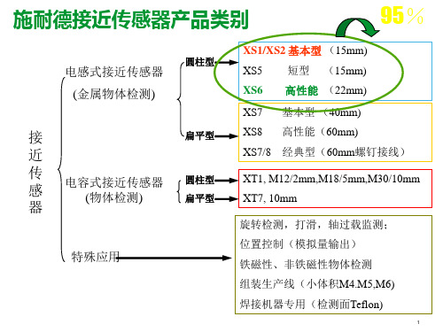
施耐德传感器及安全产品介绍课件
光纤设计
XUX
XUD A2
+ 显示
金属/塑料
金属/塑料
塑料 可选继电器输出
塑料 螺钉接线
自学习模式
26
光电传感器-新XUM卖点及目标行业
产品优势
同类产品中检测距离最长:对射式15m,反射式5m,漫反射式1m NO/NC可调 抗光干扰强度高:自然光40,000LUX/白炽灯10,000LUX 节能增效--同样供电条件下,可使用2倍数量的传感器 防相互干扰:几个传感器可近距离安装同时使用 极具竞争力的价格优势 输出状态指示灯在接收器的前表面,进一步改善安装的统一性 耐环境性能高:-30 到60 ℃的工作温度,防护等级IP67
参数性能。并且注意传感器的输出逻辑形式。
11
XSAV失速保护传感器 性能对比
12
重点产品线XS6*-产品介绍
以最优异的性能满足苛刻的使用要求
➢检测距离:埋入式 2.5-15mm;非埋入式 2.5-22mm;
➢电缆材料:PVR 耐化学腐蚀,耐磨及不宜老化,完全符合阻燃标准 NFC 32-070;
➢电源: DC 10~58V; AC20~264V; ➢输出方式: DC 3线/AC&DC 2线; ➢开关容量:200mA DC;300mA AC;
钢滚轮直动式
XCKJ167H29C WLD2 ZR335-11Z SZL-WL-E TZ5102/TZ5103
直动式
XCKJ10559H29C WLCL Z4V10H335-11Z SZL-WL-C TZ5107
35
限位开关重点产品XCKM-产品介绍
中重载应用
注塑机、纺织机械、印刷机械、物料搬运机械 机床,木工机械,生产线 …
经典型 XCK-J
JUMO MIDAS C08 OEM 压力传感器 数据表 401002说明书
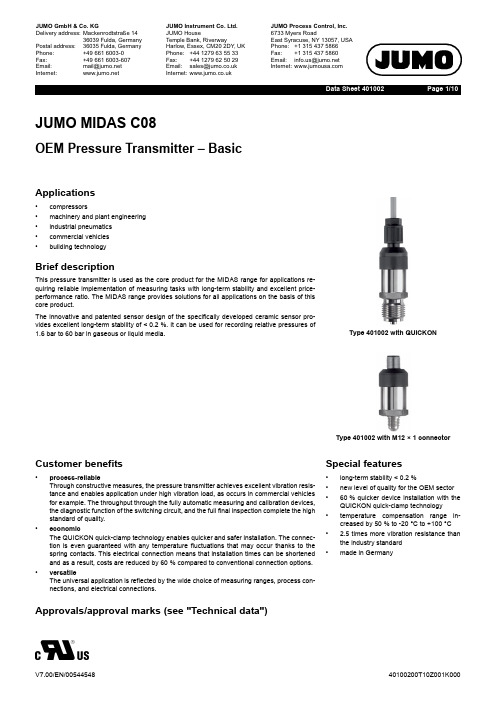
Page 1/10Data Sheet 401002JUMO MIDAS C08OEM Pressure Transmitter – BasicApplications•compressors•machinery and plant engineering •industrial pneumatics •commercial vehicles •building technologyBrief descriptionThis pressure transmitter is used as the core product for the MIDAS range for applications re-quiring reliable implementation of measuring tasks with long-term stability and excellent price-performance ratio. The MIDAS range provides solutions for all applications on the basis of this core product.The innovative and patented sensor design of the specifically developed ceramic sensor pro-vides excellent long-term stability of <0.2%. It can be used for recording relative pressures of 1.6bar to 60bar in gaseous or liquid media.Type 401002 with QUICKONType 401002 with M12×1 connectorCustomer benefits•process-reliableThrough constructive measures, the pressure transmitter achieves excellent vibration resis-tance and enables application under high vibration load, as occurs in commercial vehicles for example. The throughput through the fully automatic measuring and calibration devices,the diagnostic function of the switching circuit, and the full final inspection complete the high standard of quality.•economicThe QUICKON quick-clamp technology enables quicker and safer installation. The connec-tion is even guaranteed with any temperature fluctuations that may occur thanks to the spring contacts. This electrical connection means that installation times can be shortened and as a result, costs are reduced by 60 % compared to conventional connection options.•versatileThe universal application is reflected by the wide choice of measuring ranges, process con-nections, and electrical connections.Special features•long-term stability <0.2%•new level of quality for the OEM sector •60% quicker device installation with the QUICKON quick-clamp technology •temperature compensation range in-creased by 50 % to -20°C to +100°C • 2.5 times more vibration resistance than the industry standard •made in GermanyApprovals/approval marks (see "Technical data")Page 2/10Data Sheet 401002Technical dataGeneral InformationMeasuring range and accuracyReference conditions DIN 16086 and DIN EN 60770SensorMeasuring principle Thick film on ceramic bodies (piezo-resistive)Admissible load changes >10million, 0to 100% measuring range Mounting position AnyCalibration positionDevice upright, process connection at the bottom Measuring rangeLinearity a Accuracy at Long-term stability b Overload capacity c Burst pressure 20°C d -10to +85°C e -20to +100°C e % MSP f% MSP % MSP % MSP % MSP per year bar bar 0to 1.6bar relative pressure 0.250.50.6510.26120to 2.5bar relative pressure 6120to 4bar relative pressure 0.350.512250to 6bar relative pressure 12250to 10bar relative pressure 20380to 16bar relative pressure 50750to 25bar relative pressure 50750to 40bar relative pressure 1202000to 60bar relative pressure 120200-1to +0.6bar relative pressure 0.50.65612-1to +1.5bar relative pressure 612-1to +3bar relative pressure 0.350.51225-1to +5bar relative pressure 1225-1to +9bar relative pressure 2038-1to +15bar relative pressure 5075-1to +24bar relative pressure5075a Linearity according to limit point settingb Reference conditions EN 61298-1c All pressure transmitters are vacuum-proof.d Includes: linearity, hysteresis, repeatability, deviation of measuring range initial value and measuring range end valuee Includes: linearity, hysteresis, repeatability, deviation of measuring range initial value and measuring range end value, thermal effect on mea-suring range start and measuring span fMSP = Measuring spanPage 3/10Data Sheet 401002OutputMechanical featuresAnalog output a Current 4to 20mA, two-wire (output 405)VoltageDC 0.5to 4.5V, three-wire,ratiometric 10to 90% of the voltage supply (output 412)DC 0to 10V, three-wire (output 415)DC 1to 5V, three-wire (output 418)DC 1to 6V, three-wire (output 420)Step response T 90≤2msBurden CurrentR L ≤(U B -8V)÷0.02A (Ω) at 4to 20mA, two-wire (output 405)Voltage(burden connected to "0V/S-")R L ≥5k Ω at DC 0.5to 4.5V, three-wire (output 412)R L ≥10k Ω at DC 0to 10V, three-wire (output 415)R L ≥10k Ω at DC 1to 5V, three-wire (output 418)R L ≥10k Ω at DC 1to 6V, three-wire (output 420)aFurther outputs are available upon request.MaterialProcess connection Stainless steel 304for push-in fitting(process connection 383)Brass, nickel-plated Seal 600 (internal a )EPDM Seal 601 (internal a)FKM, standard Seal 602 (internal a )CR Seal 604 (internal a )FFKM Seal 609 (internal a )NBR for G 1/4 (process connection 521)(external a )FKMSensor Ceramic Al 2O 3 96%HousingStainless steel 304Attached cable(electrical connection 11)PBT-GF30, PVC QUICKON(electrical connection 23)PBT-GF30Round plug M12×1 (electrical connection 36)PBT-GF30, stainless steel 303L Bayonet connector(electrical connection 53)PBT-GF30Cable socket(electrical connection 61)PBT-GF30, PA, siliconeWeight70g with G 1/4 (process connection 502)aEnsure the medium durability of the seal material!Page 4/10Data Sheet 401002Environmental influencesMedium temperature for electrical connection Attached cable -20to +125°C Round plug M12×1-20to +125°C Bayonet connector -20to +125°C Cable socket -20to +125°CAmbient temperature for electrical connection Attached cable-20to +100°CAt ambient temperature of -30°C restricted function. Only use when stationary. Risk of cable break.Round plug M12×1-20to +100°C Bayonet connector -20to +100°C Cable socket -20to +100°C Storage temperature for electrical connection Attached cable -30to +100°C Round plug M12×1-40to +100°C Bayonet connector -40to +100°C Cable socket -40to +100°CAdmissible humidity Operation 100% rel. humidity including condensation on the device outer case Storage90% rel. humidity without condensationAdmissible mechanical load Vibration resistance 50g for 10to 2000Hz, according to IEC 60068-2-6Shock resistance50g for 3ms, 100g for 2ms, according to IEC 60068-2-27Electromagnetic compatibility according to EN 61326-2-3Interference emission Class B aInterference immunity Industrial requirement Protection typefor electrical connection according to EN 60529Attached cable IP67QUICKON b IP67Round plug M12×1cIP67Bayonet connector c IP67Cable socket c, dIP65a The product is suitable for industrial use as well as for households and small businesses.b Connecting cable diameter, minimum 3.5mm, maximum 6mmc The protection type is only achieved with a suitable mounted counter piece.dConnecting cable diameter, minimum 6mm, maximum 8mmPage 5/10Data Sheet 401002Auxiliary powerApprovals/approval marksVoltage supply U B a4to 20mA, two-wire (output 405)DC 8to 30V, rated voltage supply DC 24V DC 0.5to 4.5V, three-wire (output 412)DC 3to 5.25V, rated voltage supply DC 5V,ratiometric output 10to 90% of the voltage supply DC 0to 10V, three-wire (output 415)DC 11.5to 30V, rated voltage supply DC 24V DC 1to 5V, three-wire (output 418)DC 8to 30V, rated voltage supply DC 24V DC 1to 6V, three-wire (output 420)DC 8to 30V, rated voltage supply DC 24V Current consumption incl. load 4to 20mA, two-wire (output 405)≤25mA DC 0.5to 4.5V, three-wire (output 412)≤3mA DC 0to 10V, three-wire (output 415)≤3mA DC 1to 5V, three-wire (output 418)≤3mA DC 1to 6V, three-wire (output 420)≤3mA Reverse voltage protection Yes Electrical circuit SELVRequirementsThe device must be equipped with an electrical circuit that meets the requirements of EN 61010-1 with regardto "Limited-energy circuits".aResidual ripple: the voltage peaks must not exceed or fall below the specified voltage supply values!Approval mark Testing agency Certificate/certification num-ber Inspection basisValid forc UL usUnderwriters LaboratoriesE201387UL 61010-1 (3. Ed.),CAN/CSA-22.2No.61010-1(3. Ed.)Only in connection with extra code 061;observe order detailsPage 6/10Data Sheet 401002DimensionsElectrical connectionPage 7/10Data Sheet 401002Process connectionØ8mm*Extra code 630 pressure channel Ø8mmPage 8/10Data Sheet 401002Connection diagramThe connection diagram in the data sheet provides preliminary information about the connection options. For the electrical connection, only use the installation instructions or the operating manual. The knowledge and the correct technical compliance with the safety information and warnings contained in these documents are mandatory for mounting, electrical connection, and startup as well as for safety during operation.Cable socketnection.Color coding: connecting cable round plug M12×11 BN Brown2 WH White3 BU Blue4 BKBlackThe color coding is only valid for A-coded standard cables!Page 9/10Data Sheet 401002Order details(1)Basic type401002/000JUMO MIDAS C08 – OEM pressure transmitter – basic401002/999JUMO MIDAS C08 – OEM pressure transmitter – basic, special version (2)Input4550to 1.6bar relative pressure 4560to 2.5bar relative pressure 4570to 4bar relative pressure 4580to 6bar relative pressure 4590to 10bar relative pressure 4600to 16bar relative pressure 4610to 25bar relative pressure 4620to 40bar relative pressure 4630to 60bar relative pressure 479-1to +0.6bar relative pressure 480-1to +1.5bar relative pressure 481-1to +3bar relative pressure 482-1to +5bar relative pressure 483-1to +9bar relative pressure 484-1to +15bar relative pressure 485-1to +24bar relative pressure999Special measuring range for relative pressure (3)Output4054to 20mA, two-wire4120. 5to 4.5V, three-wire, ratiometric 4150to 10V, three-wire 4181to 5V, three-wire 4201to 6V, three-wire (4)Process connection383Push-in fitting for pipe/hose 6×4DN 6502G 1/4 DIN EN 837504G 1/2 DIN EN 8375111/4-18 NPT DIN EN 837521G 1/4 DIN 547Rp 1/8 inside 5627/16-20 UNF(5)Process connection material 20CrNi (stainless steel)(6)Material seal 600EPDM 601FKM a 602CR 604FFKM 609NBR999Special materialPage 10/10Data Sheet 401002Accessories(7)Electrical connection 11Attached cable b 23Quickon36Round plug M12×153Bayonet connector DIN 7258561Cable socket DIN EN 175301-803, Form A (8)Extra codes 000None 061UL approval c591Choke in the pressure channel 624Oil and grease free 630Enlarged pressure channel d 876Test reporta Standardb The standard cable length is 2m. Further lengths are available upon request.c The UL approval stipulates use of the pressure transmitter indoors. In addition, process connection 383 as well as seals 609 and 999 are not possible. Special measuring ranges (input) are not allowed to exceed the 60 bar limit.dAn enlarged pressure channel of diameter Ø8mm is only available with process connection 1/4-18 NPT (process connection 511), G 1/4 (pro-cess connection 521) and the seal FKM (seal material 601).(1)(2)(3)(4)(5)(6)(7)(8)Order code ------/ , ...aOrder example401002/000-460-412-504-20-600-36/591aList extra codes in sequence, separated by commas.Minimum order volume for manufacturing devices: 5 pieces Minimum order volume for warehouse devices:1 pieceItemDescriptionPart no.Cable box, straightThe PVC connecting cable is 2m in length and has a 4-pin, straight M12×1 connector with gold-plated contacts on the device side.00404585Cable box, angledThe PVC connecting cable is 2m in length and has a 4-pin, angled M12×1 connector with gold-plated contacts on the device side.00409334。
埃斯利姆兹菲尔德传感器选型指南说明书
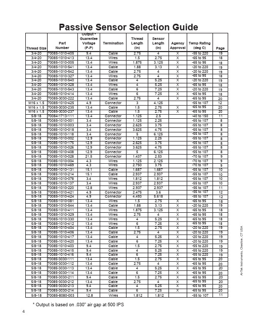
AS U T C ,e r i h s e h C ,s t n e m u r t s n I k e T -I A Passive Sensor Selection GuideThread Size Part Number Output *Guarentee Voltage (P-P)Termination Thread Length (in)Sensor Length (in)Agency Approval Temp Rating (deg C)Page 3/4-2070085-1010-4059.4Cable 2.754X-55 to 2203/4-2070085-1010-41313.4Wires 1.5 2.75X -65 to 953/4-2070085-1010-00513.4Wires 1.875 3.125X -65 to 953/4-2070085-1010-54113.4Cable 1.88 3.13X -20 to 2203/4-2070085-1010-54213.4Cable 2.754X -20 to 2203/4-2070085-1010-32713.4Wires 2.754X -65 to 953/4-2070085-1010-54013.4Cable 4 5.25X -20 to 2203/4-2070085-1010-32813.4Wires 4 5.25X -65 to 953/4-2070085-1010-54313.4Cable 67.25X -20 to 2203/4-2070085-1010-41413.4Wires 67.25X -65 to 953/4-2070085-3030-22213.4Cable 2.754X -65 to 95M16 x 1.570085-1010-425 4.9Connector 3 4.125 -55 to 107M16 x 1.570085-3030-23513.4Cable 1.5 2.75X -65 to 95M16 x 1.570085-3030-23713.4Cable 1.5 2.75X-65 to 955/8-1870084-1713-11113.4Connector 1.125 2.5 -40 to 1505/8-1870085-1010-001 3.4Connector 1.125 2.25 -55 to 1075/8-1870085-1010-003 3.4Connector 2.625 3.75 -55 to 1075/8-1870085-1010-018 3.4Connector 3.625 4.75 -55 to 1075/8-1870085-1010-118 3.4Connector 5 6.125 -55 to 1075/8-1870085-1010-00212.9Connector 1.125 2.25 -55 to 1075/8-1870085-1010-17512.9Connector 2.625 3.75 -55 to 1075/8-1870085-1010-02612.9Connector 3.625 4.75 -55 to 1075/8-1870085-1010-40812.9Connector 5 6.125 -55 to 1075/8-1870085-1010-02821.5Connector 1.437 2.53 -70 to 1075/8-1870085-1010-004 4.3Wires 1.125 2.125 -70 to 1075/8-1870085-1010-469 4.3Wires 2.750 3.75 -70 to 1075/8-1870085-1010-13115.1Cable 1.687 1.687 -55 to 1075/8-1870085-1010-21415.1Cable 2.937 2.937 -55 to 1075/8-1870085-1010-078 3.4Wires 1.812 1.812 -55 to 1075/8-1870085-1010-137 3.4Wires 2.937 2.937 -55 to 1075/8-1870085-1010-22012.8Wires 2.937 2.937 -55 to 1075/8-1870085-1010-421 4.9Connector 2.475 3.6 -55 to 1075/8-1870085-1010-424 4.9Connector 4.493 5.618 -55 to 1075/8-1870085-1010-08113.4Wires 1.5 2.75X -65 to 955/8-1870085-1010-54413.4Cable 1.88 3.13X -20 to 2205/8-1870085-1010-41113.4Wires 1.875 3.125X -65 to 955/8-1870085-1010-32913.4Wires 2.754X -65 to 955/8-1870085-1010-33013.4Wires 4 5.25X -65 to 955/8-1870085-1010-41213.4Wires 67.25X -65 to 955/8-1870085-1010-40413.4Cable 1.5 2.75X -20 to 2205/8-1870085-1010-40613.4Cable 2.754X -20 to 2205/8-1870085-1010-41713.4Cable 4 5.25X -20 to 2205/8-1870085-1010-42013.4Cable 67.25X -20 to 2205/8-1870085-1010-4039.4Cable 1.5 2.75X -55 to 2205/8-1870085-1010-4159.4Cable 4 5.25X -55 to 2205/8-1870085-1010-4169.4Cable 67.25X -55 to 2205/8-1870085-3030-11113.4Cable 1.5 2.75X -65 to 955/8-1870085-3030-11213.4Cable 2.754X -65 to 955/8-1870085-3030-11313.4Cable 4 5.25X -65 to 955/8-1870085-3030-11413.4Cable 67.25X -65 to 955/8-1870085-3030-2119.4Cable 1.5 2.75X -65 to 955/8-1870085-3030-21213.4Cable 2.754X -65 to 955/8-1870085-3030-2139.4Cable 4 5.25X -65 to 955/8-1870085-3030-2149.4Cable 67.25X-65 to 9545/8-1870085-8080-00312.8Wires1.8121.812-55 to 107* Output is based on .030" air gap at 500 IPS191818191918191819182012202011888888889991010101011121218191818181819191919191919202020202020202011A I -T e k I n s t r u m e n t s ,C h e s h i r e ,C T U S A5Magnetic Sensor SelectionThe following information is supplied for assistance in selecting the proper sensors for yourp articular applications. One of the fundamental questions to be answered is, “Will there be enough sensor output voltage at the lowest operating speed?”The sensor output voltage depends on:• Surface Speed - speed target passes pole piece • Gap - distance between target and pole pieceThe load impedance, with relation to the internal impedance of the sensor, dictates the amount of sensor output voltage that will be seen by that load. Magnetic sensors are designed with thel owest practical impedance consistent with providing maximum output. The load impedance should be high in relation to the impedance of the sensor to minimize the voltage drop across the coil and to deliver the maximum output to the load.Most of the output voltages listed in this catalog are based on a load impedance of 100k ohms.To use a generality, the load impedance should be 10 times that of the sensor.In order to assist you in selecting your sensor, Al-Tek Instruments has developed an output vs.speed curve for each sensor family. By looking at the application extremes of highest speed/lowest gap and lowest speed/highest gap, the full variation of sensor output can easily be determined. We also specify each family in two ways: Standard - minimum output voltage at 1000 IPS, 0.005 in.gap. Guarantee Point - minimum output voltage at 500 IPS, 0.030 in. gap. Sensors with .187” dia.pole piece are tested with an 8 D.P . gear, 100k ohms load; .106” dia. & smaller pole piece sensors are tested with a 20 D.P . gear, 100k ohms load. Sensors with connectors also use a 250 pf capaci-tor shunted across the load.1. Dimension of tooth 4 Pole piece diameter top surface2. Tooth height5. Air gapA I -T e k I n s t r u m e n t s ,C h e s h i r e ,C T U S A6。
电感式接近开关传感器的选型及使用调试方法

电感式接近开关传感器的选型及使用调试方法一、电感式接近开关的选型1.工作频率:电感式接近开关一般有低频和高频两种。
低频电感式接近开关适用于静态测量,高频电感式接近开关适用于动态测量。
2.工作距离:电感式接近开关的工作距离是指传感器与被测金属物体之间的最大距离。
根据具体应用需求选择合适的工作距离。
3.输出信号:电感式接近开关的输出信号可以是模拟信号或数字信号。
模拟信号一般是指传感器输出的电流或电压,数字信号一般是指传感器输出的开关量。
4.材料和环境要求:根据具体工作环境选择合适的电感式接近开关。
要考虑温度、湿度、腐蚀性等因素对传感器的影响。
二、电感式接近开关的使用方法1.安装位置:电感式接近开关应安装在被测金属物体附近。
距离传感器的安装位置应根据具体测量要求选择,一般要考虑金属物体的形状、大小和位置等因素。
2.连接方法:将电感式接近开关与测量系统连接,可以使用导线或连接器进行连接。
注意接线的正确性,确保连接牢固可靠。
3.调节灵敏度:电感式接近开关一般具有灵敏度调节装置,可根据具体测量要求进行灵敏度调节。
一般来说,灵敏度越高,工作距离越近。
4.补偿温度:电感式接近开关的输出信号可能受到温度的影响,需要进行温度补偿。
可以使用温度补偿电路或选择具有温度补偿功能的传感器。
三、电感式接近开关的调试方法1.调试高频电感式接近开关:先将传感器与测量系统连接好,打开电源。
通过调节灵敏度装置,使传感器能够准确地感应到金属物体的位置。
可使用示波器等测试工具观察输出信号的波形,确保信号稳定和准确。
2.调试低频电感式接近开关:将传感器与测量系统连接好,打开电源。
使用测量仪器(如万用表)测量输出信号的电流或电压值,根据实际需求进行灵敏度调节。
3.调试温度补偿功能:根据传感器的使用说明书,连接温度补偿电路或调节传感器上的温度补偿装置。
通过改变传感器的工作温度,观察输出信号的变化,判断是否达到温度补偿的效果。
通过以上选型、使用和调试方法,可以正确选择、使用和调试电感式接近开关传感器。
电感式接近开关传感器的选型及使用、调试方法
电感式接近开关传感器的选型及使用、调试方法正文:一、介绍电感式接近开关传感器是一种常用的非接触式传感器,可用于检测金属物体的接近情况。
本文将介绍电感式接近开关传感器的选型、使用以及调试方法,以帮助用户正确选择、安装和调试该类型传感器。
二、选型1:工作原理电感式接近开关传感器通过检测金属物体引起的电感变化来实现物体的接近检测。
在工作时,传感器发射高频电磁信号,当金属物体靠近传感器时,物体会对电磁信号产生干扰,从而导致电感的变化。
传感器通过检测电感的变化来判断物体的接近情况。
2:选型要点在选择电感式接近开关传感器时,需要考虑以下几个要点:- 检测距离:传感器的检测距离应满足实际应用需求,过远或过近都会影响检测的精度。
- 工作频率:传感器的工作频率应与应用场景相匹配,以保证传感器的检测能力。
- 输出类型:传感器通常提供模拟输出或数字输出,根据实际需求选择适合的输出类型。
- 环境适应性:传感器应具备较好的抗干扰能力,能够适应恶劣的环境条件。
三、使用方法1:安装在安装电感式接近开关传感器时,需要注意以下几点:- 传感器与金属物体之间的距离应满足传感器的检测要求。
- 传感器的安装位置应远离强磁场、强电场以及其他可能干扰传感器工作的设备。
- 传感器应与相关设备的接线正确连接,确保正常工作。
2:接线根据传感器的接口类型和输出类型,将传感器正确接入目标设备。
- 模拟输出:将传感器的模拟输出接入目标设备的模拟输入端口。
- 数字输出:将传感器的数字输出接入目标设备的数字输入端口。
3:调试在完成安装和接线后,需要对传感器进行调试,确保其正常工作:- 应用合适的金属物体靠近传感器,观察传感器的输出信号变化情况。
- 根据实际需要,调整传感器的灵敏度和工作距离,以满足具体应用的要求。
四、附件本文档附带以下附件供参考:- 传感器选型表格:包含常见电感式接近开关传感器的技术参数和特性,供用户参考选型。
- 传感器安装示意图:展示了传感器的安装方法和注意事项。
电感式接近开关传感器的选型及使用调试方法
电感式接近开关传感器的选型及使用调试方法电感式接近开关传感器是一种常用于检测金属物体的接近或远离的传感器。
它利用电磁感应原理来实现物体接近或远离的检测,并将信号转化为电信号输出。
这种传感器具有结构简单、稳定可靠、响应速度快等优点,被广泛应用于工业自动化控制系统中。
选型方面,需要根据具体的应用场景和需求来选择合适的电感式接近开关传感器。
以下是一些常见的选型考虑因素:1.检测距离:根据需要检测的物体与传感器之间的距离,选择具有适当检测距离的传感器。
2.工作频率:不同的电感式接近开关传感器具有不同的工作频率范围。
需要根据具体应用场景来选择适当的工作频率。
3.输出类型:传感器的输出类型可以是模拟输出或数字输出。
根据实际需要来选择合适类型的传感器。
4.环境要求:考虑工作环境的温度、湿度、防护等级等要求,选择适应该环境的传感器。
在使用电感式接近开关传感器时,需要注意以下几点:1.安装位置:将传感器正确安装在需要检测物体的位置,确保与物体之间的距离符合传感器的检测范围。
2.供电电源:将传感器接入适当的电源电压,一般为直流电源。
3.输出接口:根据传感器的输出类型,选择合适的接口来接收传感器的输出信号。
4.参数设置:一些传感器可能具有一些可调参数,如灵敏度、反向保护等,需要根据具体需要进行设置。
在调试过程中1.测试物体:使用合适的金属物体作为测试物体,可以通过将物体靠近或离开传感器来观察传感器的响应情况。
2.调节灵敏度:如果传感器的灵敏度可以调节,可以根据实际需求来调节灵敏度,使得传感器可以准确检测到目标物体的接近或离开。
3.监测输出信号:使用示波器或其他合适的设备监测传感器的输出信号,观察信号的波形、稳定性等。
4.调整位置:如果传感器在特定位置无法正常工作,可以调整传感器的位置,试图找到合适的位置。
5.参考厂家文档:根据传感器的厂家文档,了解传感器的使用方法和注意事项,以便更好地进行调试。
以上是关于电感式接近开关传感器的选型、使用和调试方法的介绍。
电感式接近开关传感器的选型及使用、调试方法
电感式接近开关传感器的选型及使用、调试方法电感式接近开关传感器的选型及使用、调试方法1. 电感式接近开关传感器简介电感式接近开关传感器是一种常见的非接触式传感器,其工作原理是通过探测金属物体的磁场变化来实现对物体接近状态的检测。
该传感器广泛应用于各种自动化控制系统中,如机械、电子、汽车等领域。
2. 电感式接近开关传感器的选型在选择适合的电感式接近开关传感器时,需要考虑以下几个因素:2.1 工作距离工作距离是指传感器能够探测到物体的最大距离。
根据具体的应用需求,选择合适的工作距离可以确保传感器能够正常工作。
2.2 环境温度环境温度是指传感器所处环境的工作温度范围。
根据实际应用情况,选择耐高温或耐低温的传感器可以保证其在各种环境条件下的可靠性。
2.3 尺寸和安装方式传感器的尺寸和安装方式需与安装空间相适应。
需要考虑的因素包括传感器的大小、安装孔的尺寸以及安装固定方式等。
2.4 输出类型根据具体应用需求,传感器的输出类型可能为开关量信号(如继电器输出)、模拟量信号(如电压、电流输出)或数字信号(如RS485通信)。
根据系统接收信号的方式,选择合适的输出类型非常重要。
3. 电感式接近开关传感器的使用方法3.1 安装在安装电感式接近开关传感器之前,应确保目标物体符合传感器的检测要求,并正确安装传感器到所需位置。
安装时需要注意以下几点:- 确保传感器与目标物体之间的距离符合传感器的工作距离要求。
- 避免传感器与其他金属物体产生干扰,确保传感器可以准确探测目标物体。
- 使用适当的固定装置,确保传感器稳固地安装在所需位置上。
3.2 连接将传感器的输出端与控制系统连接,根据传感器的输出类型选择正确的连接方式。
常见的连接方式包括继电器接线、电压或电流输入接口、RS485通信接口等。
在连接时需要注意以下几点:- 确保连接线的质量良好,避免因连接线故障导致信号不正常。
- 遵循正确的接线方法,防止接线错误导致的故障。
- 根据传感器的规格书或技术说明书,正确设置控制系统的参数。
Micro Detectors C18 型号的近距离传感器说明书
Proximity SensorCatalogueCod. CAT3EC11265301Datasheet - C18 - English - Ed.01/2012M18 cylindrical capacitive Sensor C182/3C18SeriesProductscapacitivecylindricalcapacitivecylindricalDC or AC supply voltage High noise immunityShielded and unshielded models Adjustable sensitivity Plastic housingfeaturesapprovalsprotection degreeIP674/5C18 capacitive Proximity Sensors are made in a M18 polyester threaded housing. Their high techno-logy can grant a high noise immunity.Output indication is activated through yellow LED. SCR output is normally closed or normally open. 2 mt. long cable or M12 plug models are available. All sensors have an IP67 protection degree.M18 cylindrical capacitive Sensor C18pack contentfurther commercial and technical documents availableDatasheet (Italian: CAT3ICQ1264301 and Spanish: CAT3SCQ1264501)High resolution picturesApplication notes:- position detection of buckets, dumpers, loadersin diggers (English: CAT3E001262001, Italian: CAT3I001261901 & Spanish: CAT3S001262101)- detection of food in automatic mangers (English: CAT3E001262301, Italian: CAT3I001262201, & Spanish: CAT3S001262401)- water level detection in whirlpool baths (English: CAT3E001262601, Italian: CAT3I001262501 & Spanish: CAT3S001262701)- soaps and waxes level in automatic washing systems (English: CAT3E001262901, Italian: CAT3I001262801, & Spanish: CAT3S001263001)- water level detection in automatic washing systems (English: CAT3E001263201, Italian: CAT3I001263101 & Spanish: CAT3S001263301)- goods detectioninside boxes (English: CAT3E001263501, Italian: CAT3I001263401 & Spanish: CAT3S001263601)- freeze-dried products detection in vending machines (English: CAT3E001263801, Italian: CAT3I001263701 & Spanish: CAT3S001263901)- photovoltaic panles presence and position detection (English: CAT3E001264101, Italian: CAT3I001264001 & Spanish: CAT3S001264201)ProductsInstruction manual (English + Italian): CAT8BCT1259401-custom models already testedminimum quantity that can be ordered1 piececapacitivecylindricalcode descriptionavailable models6/7C18P/**-1*C18P/**-2*technical speci fi cationsaccording to IEC EN 60947-5-2 and IEC EN 60947-5-7Productscapacitivecylindricalø 18trimmermmC18*/**-*E (plug exit)C18*/**-*A (cable exit)LEDø 188(*)52.346.525671.515.5ø 10ø 5.282,000trimmerLED 8(*)52.345.522.8669.314.28ø 18plugexitplug exit(*)unshielded modelsProximity SensorsCatalogueCAT3EC11265301 DATASHEET C18 ENGLISH ED.01/2012All information written in this catalogue are subject to modifications without notice.They don’t represent any obligation for M.D. Micro DetectorsAny variation will be implemented in this catalogue and its electronic version, available on the corresponding page of M.D. Micro Detectors website:。
- 1、下载文档前请自行甄别文档内容的完整性,平台不提供额外的编辑、内容补充、找答案等附加服务。
- 2、"仅部分预览"的文档,不可在线预览部分如存在完整性等问题,可反馈申请退款(可完整预览的文档不适用该条件!)。
- 3、如文档侵犯您的权益,请联系客服反馈,我们会尽快为您处理(人工客服工作时间:9:00-18:30)。
IME08-IME08-1B5NOZTOS IME08-1B5NOZW2S IME08-1B5NSZTOS IME08-1B5NSZW2S IME08-1B5POZTOS IME08-1B5POZW2S IME08-1B5PSZTOS IME08-1B5PSZW2S
1 040 8501 040 8521 040 8461 040 8481 040 8421 040 8441 040 8381 040 840
1B5NO ZT0S 1B5NO ZW2S 1B5NS ZT0S 1B5NS ZW2S 1B5PO ZT0S 1B5PO ZW2S 1B5PS ZT0S 1B5PS ZW2S
钢铁(ST37)不锈钢(V2A )铝(实心)铜(Cu )
1约为0.8约为0.45约为0.4
下列为参考数值,实际中因型号的不同而不同修正因素
订货号
订货资料型号
技术资料
5)螺纹直径x 螺距(mm )6)
短路保护(脉冲)
1)
在I 最大时a 2)
无荷载
3)
S r
4)符合标准EN60529
219
工业传感器工
业传感器
IME08-2N5NOZT0S IME08-5NOZW2S2N IME08-5NSZT0S2N IME08-5NSZW2S2N IME08-5POZT0S2N IME08-5POZW2S2N IME08-5PSZT0S2N IME08-5PSZW2S2N
1 040 8661 040 8681 040 8621 040 8641 040 8581 040 8601 040 8541 040 856
IME08-2N5N 0ZT0S 2N5NO ZW2S 2N5NS ZT0S 2N5NS ZW2S 2N5PO ZT0S 2N5PO ZW2S 2N5PS ZT0S 2N5PS ZW2S
技术资料
5)螺纹直径x 螺距(mm )6)
短路保护(脉冲)
1)
在I 最大时a 2)
无荷载
3)
S r
4)符合标准
EN60529
钢铁(ST37)不锈钢(V2A )铝(实心)铜(Cu )
1约为0.8约为0.45约为0.4
下列为参考数值,实际中因型号的不同而不同修正因素
订货号
订货资料型号
221
工业传感器工
业传感器
IME08-IME08-02BNOZT0S 1 040 882IME08-NOZW2S02B 1 040 884IME08-NSZT0S02B 1 040 878IME08-NSZW2S02B 1 040 880IME08-POZT0S02B 1 040 874IME08-POZW2S02B 1 040 876IME08-PSZT0S02B 1 040 870IME08-PSZW2S02B
1 040 872
02BNO ZT0S 02BNO ZW2S 02BNS ZT0S 02BNS ZW2S 02BPO ZT0S 02BPO ZW2S 02BPS ZT0S 02BPS
ZW2S
技术资料
钢铁(ST37)不锈钢(V2A )铝(实心)铜(Cu )
1约为0.8约为0.45约为0.4
下列为参考数值,实际中因型号的不同而不同修正因素
订货号
订货资料型号
5)螺纹直径x 螺距(mm )6)
短路保护(脉冲)
1)
在I 最大时a 2)
无荷载
3)
S r
4)符合标准EN60529
223
工业传感器工
业传感器
IME08-IME08-04NNOZT0S 1 040 898IME08-NOZW2S04N 1 040 900IME08-NSZT0S04N 1 040 894IME08-NSZW2S04N 1 040 896IME08-POZT0S04N 1 040 890IME08-POZW2S04N 1 040 892IME08-PSZT0S04N 1 040 886IME08-PSZW2S04N
1 040 888
04NNO ZT0S 04NNO ZW2S 04NNS ZT0S 04NNS ZW2S 04NPO ZT0S 04NPO ZW2S 04NPS ZT0S 04NPS
ZW2S
技术资料
钢铁(ST37)不锈钢(V2A )铝(实心)铜(Cu )
1约为0.8约为0.45约为0.4
下列为参考数值,实际中因型号的不同而不同修正因素
订货号
订货资料型号
5)螺纹直径x 螺距(mm )6)
短路保护(脉冲)
1)
在I 最大时a 2)
无荷载
3)
S r
4)符合标准EN60529
225
工业传感器工
业传感器。