simufact.forming实例分析教程(锻造)
simufact.Forming10.0新功能介绍
S i m u f a c t .f o r m i n g 10.0simufact.forming 10.0u总览u改进前处理功能u 新功能菜单u 更加灵活的定义u改进后处理功能u改进并行计算能力u改进模具应力分析功能u改进钣金成形模块u改进机构运动模块u 环轧设备运动u 开坯锻设备运动u改进网格划分功能uGP-GUI 界面u 帮助u 改进实例分析u 新用户帮助手册S i m u f a c t .f o r m i n g 10.0总览S i m u f a c t .f o r m i n g 10.0General remarksu Simufact.forming 10.0 基于§MSC 软件Marc2010和Dytran2010 §Windows 界面支持更多功能§GP-GUI 基于Mentat2010§CAD 导入基于CADfix-Version 8.0 ServicePack 1支持最新的CAD 软件版本§全新的图形界面§新的安装和文件结构§Windows 32bit and 64bit (XP , Windows 7)Linux64 (no Forming-GUI)S i m u f a c t .f o r m i n g 10.0Installationu 所有的设定都储存在一个INI 文件~USER/ AppData\Roaming\Simufact /simufact.forming_10.0.ini ØWill allow to copy the installation to other computerØUsers can use the same settingsØThe INI-file will be written when you start the first time the GUI u Ini-File can directly be copied for other users u Whole installation can be copied or mirrored without a new setupon other computersS i m u f a c t .f o r m i n g 10.0Default Unit-Systemu Default UNIT-System after the installation is Si-mm-UnitAll examples are based on this systemUnit-System can be reset by usingS i m u f a c t.f o r m i n g 10.0u Add stl-Import for CAD Preview/Import with CAD-repair functionalitybased on CADFixu Latest Version from CADFix 8.0 Service Pack1 are implemented CADFix InterfaceIntelligent model quality diagnostics and repair Automatical defeaturingAutomaticalrepair Support Assemblies Native Interfaces CA TIA V5/R20CA TIA V4/ 4.1.X, 4.2.X Pro/Engineer Wildfire 4SolidWorks 2009Unigraphics NX7Inventor 2010Neutral Interfaces ACIS R20IGES 5.3STEP AP203 & AP214Parasolid V22VDASF 2.0STLS i m u f a c t .f o r m i n g 10.0Improved View CapabilitiesS i m u f a c t .f o r m i n g 10.0u Improved predefined view concept u 3 different View and Zoom settings can be stored 1.Global for all GUI ’s which are opened from the user 2.Stored for the current project 3.Stored for each processàThis option allows to define more flexible the view and zoomfactor for a more easy post processing and for variationsS i m u f a c t .f o r m i n g 10.0u New global setting for edge angle for outline view Edge angle = 5 deg Edge angle = 30 degS i m u f a c t .f o r m i n g 10.0u New option to control Cache for Graphicusupport huge models u Reduce out-of-memory problemsOFF : All results will not hold in the memory ON : All results are hold in th memory.Current:current used memory Clear: Clear all result information in memory Clear cache between animation steps:Results are removed from memory after each animation stepSimufact.forming1.u New option to activate filters in process and inventory windowu This allows the user to show or hide objects andprocesses very easy and concentrate on the things he want to do§eg. hide all used geometriesS i m u f a c t .f o r m i n g 10.0u Define number of entries for the “open project list ” (default: 4)S i m u f a c t .f o r m i n g 10.0uNew Cutting function with u There is a new option to decided which part should be cut 1.All components (default)2.All except workpiece 3.Only workpieceS i m u f a c t .f o r m i n g 10.0Improved Preprocessing CapabilitiesS i m u f a c t .f o r m i n g 10.0uStore comment for the projectS i m u f a c t .f o r m i n g 10.0uImproved support for default settings for process types uSettings are stored in ~InstallDir/sfForming/setting/processtype.ini u Following parameters can be predefined by the user§Default Solver and dimension, cold/or hot used for the Process§Predefined names for the tools depending on Solver and hot/cold §Number of tools used for the Process depending on Solver and hot/cold§ElementSize depending on Solver §Number of Outputresults §New: Convergence control for FE §Control parameter for forming control FE/FV §Meshertype §Ambient temperatureS i m u f a c t .f o r m i n g 10.0u Names for most objects are based on the type now including theprocess type and solver information (FE/FV)u Temperature of the die and workpiece are added to the name by defaultuNew ICON to open model view windowSim u f a c t .f o r m i n g 10.0u New Interface to Thermoprof from ABP Induction§Import temperature field based on the inductive heatingcalculation from ThermoprofSi m u f a c t .f o r m i n g 10.0u New Interface to ProCast Casting simulation softwareu Import geometry and blow whole distributionS i m u f a c t .f o r m i n g 10.0Improved Preprocessing Capabilities/Modelu Basic geometry body Cylinder are created symmetric tothe axisS i m u f a c t .f o r m i n g 10.0Improved Preprocessing CapabilitiesuEnlarge geometry in one direction to close gaps §Sometime you have small gaps in your process which are not useful for the simulation §You can enlarge it easy by using enlarge option and substitute the geometry which the new enlarged geometry geometry-EEnlarged filename is: *-ES i m u f a c t .f o r m i n g 10.0u Redesign of Positioner menuu The user can directly choosebetween Standard (with gravity)Positioner and Translation onlyu Add menu also for right mouseclickS i m u f a c t .f o r m i n g 10.0u New Function to rotate part based on the coordinate systemuRight mouse click on part 1.Relative to current position 2.absoluteS i m u f a c t .f o r m i n g 10.0uNew Interface to JMatPro §JMatPro will provide material data based on the chemical composition for a huge range and a lot of materials §This allows more material sensitive simulations § A lot of information are available also for later use (TTT etc)§JMatPro will have an export function to simufact at the endof the yearS i m u f a c t .f o r m i n g 10.0uUnits are taken from predefined settings (default mm and mm/sec) for the definition of presses u All presses which are available for FV Solver are alsoavailable for FE-Solver with all functionalities§Screw press §Counter blow Hammer §Scotch Yoke Driveu Hammer and Screw press are improved, so that the elastic effect from the dies can be taken into account uNew: Velocity table based on the diameter of a ring. This allows full flexibility for ring rolling applications uNew: Force velocity controlled press uNew: radial press with table driven velocity of the upper die (only for FE-Solver)u Presses can be mixed for FE solver (eg. CrankPress+Table)S i m u f a c t .f o r m i n g 10.0uHammer and Screw press §Support for FE and FV all functionalities §Counterblow §including efficiency factor constant variable variable with clutch §New feature to support spring effect of the dies (advanced settings)uScotch Yoke drive Press §Support for FE and FVSimufact.forming1.u New: Force velocity controlled press§Can be defined by using a table based on force/velocity§Velocity direction is controlled in forming menu§stroke has to be defined as well§Can be used similar to hydraulic pressResult from simulation:S i m u f a c t .f o r m i n g 10.0u New: radial press with table driven velocity of the upper die§Rotation path are defined based on a circle or rosette path §Can be combined with other pressesS i m u f a c t .f o r m i n g 10.0u Move friction or heat object to the processu all unassigned objects will get this friction/heatS i m u f a c t .f o r m i n g 10.0uThe die types are improved for the use with the FE-solver to make it more flexible uYou will find now:ØDie Spring ØDie Insert ØGeneric Spring ØDie Spring: The stiffness and/or Force can be defined depending on the time or displacementS i m u f a c t .f o r m i n g 10.0ØDie Insert: redefined to make it more easy to use and fully flexible. The movement can be:§Free §Fixed §Coupled with a Press (table based)§Or coupled with a generic springS i m u f a c t .f o r m i n g 10.0ØGeneric spring: a generic spring can be defined in all 3 translation directions (global or local coordinate system)and in the rotation direction as a torsion spring ØStiffness or force can be defined depending on displacement or force ØThe generic spring should be use together with a die insertS i m u f a c t .f o r m i n g 10.0Improved Preprocessing Capabilities/Contact tableu Contact tableu New: Initial stress free projection (the contact is calculated at thebeginning without a stress calculation), this is needed if you have initial penetration based on the discretization and you want to bring the parts in contact, often used if parts are glued togetherü.S i m u f a c t .f o r m i n g 10.0u Particleumost element variables can be selected for pathplotS i m u f a c t .f o r m i n g 10.0u The forming dialog is rewritten based on the new conceptwith short descriptionsuThe direction can be defined via arrows u Stroke or Time (depends on the presstype) can be setindependent from the time in the table to simulate only a part firstS i m u f a c t .f o r m i n g 10.0New terminate criteriau New terminate criteria for FE•max force for press as sumall forces of the diesof the press are cumulated§and/ormax force for each bodyand one directionS i m u f a c t .f o r m i n g 10.0u New features for sub stage dialog to support morecomplex processes very easyS i m u f a c t .f o r m i n g 10.0u You can deactivate a tool which are not used for thecalculation of the positioning of the workpiece in the first stepØEg. The blankholder is a fixed tool and have to bedeactivate for the positioning of the workpieceS i m u f a c t .f o r m i n g 10.0uYou can trim during the forming process with additional trimming tools ØYou can trim after different strokes with different tools ØIf they are not defined with a press, then they are used only for the trimming operation This allows you to form the part, trim it with a different tool and to go on with the forming processS i m u f a c t .f o r m i n g 10.0Trimmer (Cutter-1)CutterForming until 60 mm Trimming with Cutter-1Forming up to 70 mmuForming-Trimming-Forming in one runS i m u f a c t .f o r m i n g 10.u You can simulate a forward and backward motion withthe same press to have a whole cycleØYou can add a movement of a predefined press only forthe backward movementS i m u f a c t .f o r m i n g 10.0uForming process can be done in one whole cycle with forward and backward movement, kinematic for counterpunch can be deactivated for forming forward part u This is helpful for cold forming and sheet forming application where a deformations are also taken into a count in thebackward motion partS i m u f a c t .f o r m i n g 10.0 1.You can define a max. thickness for potsprocessing, so that the legend are scaled automatically, you can change this later as well 2.You can define max. distance for “Distance to Die ” Postvariabel (same as for FV), as a max Threshold 3.For 3D axissymmetric problem you can define radial&tangential results, so that you will get the vectors/tensors also in a cylindrical coordinate system 4.You can define own nodal and/or element variables which you can output by using subroutines. The names can be defined individuallyS i m u f a c t .f o r m i n g 10.0u New step size control based on the max displacementØThis can be defined also by default from the solver ØIt makes a simulation more robust, but needs generallymore stepsS i m u f a c t .f o r m i n g 10.0uSupport new solver ØThe solvers are improved ØMultiplethreading (parallel solving) are supported from ØMultifrontal Sparse solver ØCASI Solver (very fast)ØParadiso Solver ØNew: Mumps SolverØSome have a new option to speed up the solution time inthe interfaces when using DDM parallel optionS i m u f a c t .f o r m i n g 10.0u Support UsersubroutineØUser can select own subroutine and build an own version ØNeed a valid fortran licenseIntel(R) Fortran Compiler Version 10.1Requires:Microsoft(c) Visual Studio 2005 Service Pack 1Microsoft(c) Platform SDK for Windows Server 2003 SP1S i m u f a c t .f o r m i n g 10.0uThe parallel menu is redesigned and will support all parallel options ØWorkpiece only Øwill use multiple domains with remeshing of the workpiece Øonly the workpiece can be a meshed body ØMultiple bodies without remeshing Øwill use multiple domains for all meshed bodies Øwithout remeshing ØMultiple bodies with remeshing Øeach meshed body is assigned to one domain Øremeshing possibleS i m u f a c t .f o r m i n g 10.0u Starting with simufact.forming 10.0 a report can be generated in XML-format about the processuIncludes all information about the process u and the simulation parameteru informations are linkedu preview is included in the GUI。
塑性成形仿真软件simufact.forming_12.0 新功能
重新设计旋转对话框
更直观 前后旋转按钮 支持多次旋转 支持绕自定义旋转轴旋转 ( rolling) 绕特殊旋转轴旋转 (定义点)
Copyright © simufact engineering gmbh
分别定义对称面与固定面
拆分对称面/固定面定义对话框 颜色区分对称面的内外面 → 更易判断对称面内外面
Copyright © simufact engineering gmbh
CAD 导入更新
CAD接口更新至: CADfix version 9.0 SP1
(/support/cadfix/index.htm)
Support Assemblies
Copyright © simufact engineering gmbh
用户自定义网格划分
在多工况项目中可以选择原始网格来源:
创建新网格 导入上一步工序的结果网格 使用与几何模型相关联的外部生成网格 从网格文件导入用户自定义网格
进程树中可以直观看到原始网格来源:
手动创建的网格:
从上一步工序导入的结果网格:
CAD 导入
Copyright © simufact engineering gmbh
CAD 预览 (高质量面片)
改进 CAD文件导入 保证几何精度质量的情况下减少网格数量(扩大因子 expansion factor)
使用该选项减少面的数量,数值越大,面越少.
200 000 单元 Version 11.0
Copyright © simufact engineering gmbh
重新设计成形控制菜单
改进成形控制菜单结构 清楚显示停止准则(接触、力) 在首要界面清晰显示重要/常用参数(eg:并行计算)
simufact_forming_15.0安装教程

Simufact Forming 15破解版是由MSC公司推出的一款专业工业锻造过程仿真分析软件,软件基于模块化的架构方式,包含了丰富实用的功能模块,比如simufact material、simufact monitor、simufact demos、simufact remote、forming hub、rolling、hot forging等,每个模块都拥有对应的功能,可以满足不同工程人员的需求,新版本添加了全新的功能,包括设计和优化感应加热过程、扩展了模拟热处理工艺功能等,有需要的用户快快下载吧。
Simufact Forming 15安装教程1、下载后解压,主程序的格式是iso,再次解压,然后进入MAGNiTUDE文件夹,双击“MSC_Calc_20180531.exe”,输入Y生成许可文件2、接着双击“msc_licensing_11.13.1_windows64.exe”安装行可管理工具3、继续next直到安装完成就可以了4、完成后回到主目录,双击“Setup.exe”进入到Simufact Forming 15的安装向导界面,语言选择简体中文5、点击next出现协议,点击OK6、然后next选择刚刚生成的许可证文件7、继续下一步选择一下软件的安装目标文件夹,默认为“C:\Program Files”8、接着选择要安装的组件,默认已经全选了,不想要的可以将勾去掉9、点击安装就会开始Simufact Forming 15的安装了Simufact Forming功能1、Simufact Forming的图形用户界面(GUI)专为金属成型模拟而设计2、所有相关的辅助过程,例如预加热和中间加热,去毛刺和冷却过程都可以模拟与现实生活密切相关。
3、无论应用程序是什么,GUI都可以为2D和3D模拟提供单一界面。
依赖于应用程序的GUI 元素由应用程序模块提供,并无缝集成到GUI中。
这保证了短暂的初始培训阶段4、数据库存储所有模型组件和过程属性,允许重复使用所有先前的输入5、从所有常见格式导入CAD,导入整个程序集6、通过我们的合作伙伴ITI TranscenData的集成程序CADfix®自动纠正错误的CAD几何图形7、精心预定义的边界条件和自动化使用户能够生成仿真模型并在短时间内评估结果8、综合材料数据库,包含约750种材料的数据集9、模具应力模拟可以直接与成形模拟结合进行,也可以在后处理过程中进行解耦10、用于链接多阶段过程的阶段控制11、可以在任意数量的成形阶段上向前和向后跟踪后处理颗粒12、例行检查变量时,例行评估可以自动输入报告13、用于自我培训的示例和教程的综合数据库14、灵活的许可模式15、中央工作站和集群的高效远程功能simufact forming 15新功能1、设计和优化感应加热过程Simufact Forming帮助设计工程师深入了解感应加热过程。
基于simufact.forming软件的车轮旋压模拟分析
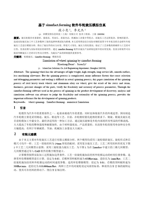
基于simufact.forming软件车轮旋压模拟仿真段小亮1,李光杰1(1.西模发特信息科技(上海)有限公司技术工程部,上海 200336)摘要:旋压轮毂具有重量轻、强度高、寿命长、表面光洁,机械加工余量少等优点。
而旋压工艺过程复杂,影响因素多,造成实际旋压加工中工艺参数和工装的选择和调试较为困难,本文采用理论结合实际对钢质重型卡车车轮及铝合金轿车车轮旋压工艺进行模拟分析,得出了旋压件的应力应变、厚度尺寸变化、旋压力变化情况,验证了工艺参数的准确性与工艺的可行性,仿真结果与实际有较好的相符性。
通过simufact.forming软件在旋压产品研制过程中的应用发现,仿真分析软件可以提前判断旋压工艺的可行性及合理性,为旋压产品的研制提供重要参考。
关键词:轮毂旋压;Simufact.forming;模拟仿真Simulation of wheel spinning by simufact.formingXiaoliang.Duan1,Jason.Li1(1.ManuSim Solutions Co,.Ltd Engineering department, Shanghai 200336)Abstract:The spinning wheel has the advantages of light weight, high strength, long service life, smooth surface, less machining allowance. But the spinning process is complicated, many influence factors that cause selection and debugging parameters and tooling is difficult in actual spinning process, this paper simulation of the spinning process of steel heavy truck wheels and aluminum alloy car wheel, give the result of the stress and strain, thickness, pressure changes of the parts, verify the feasibility and accuracy of process parameters, Through the simufact.forming software used in the process of spinning in the product development of discovery, analysis and simulation software can advance to judge the feasibility and rationality of the spinning process, provides the important reference for the development of spinning products.Keywords:wheel spinning;Simufact.forming;numerical Simulation1引言轮毂作为汽车中的重要部件之一,起着承载着汽车的重量,同时也体现着汽车的外观造型。
多工步锻造仿真分析
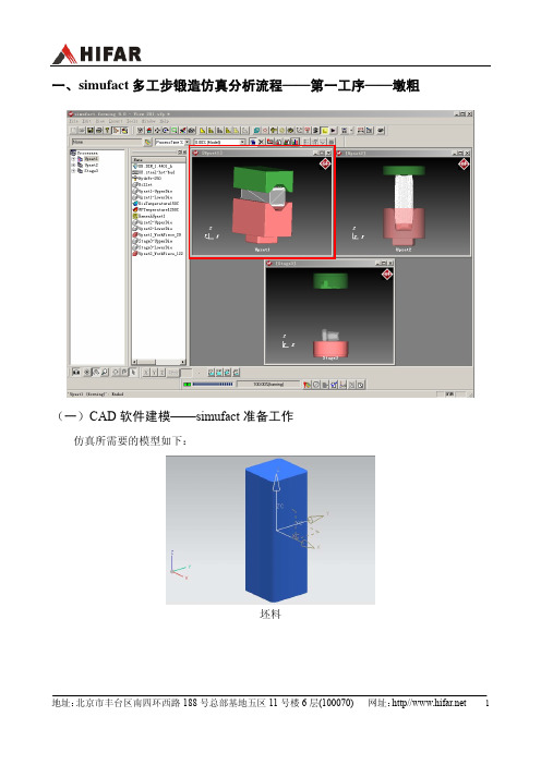
一、simufact多工步锻造仿真分析流程——第一工序——墩粗(一)CAD软件建模——simufact准备工作仿真所需要的模型如下:坯料上模下模(二)simufact墩粗工艺仿真流程在Simufact 中整个锻件的锻造过程按下述求解步骤进行:1)生成开式模锻的分析项目2)导入工件及模具几何模型3)工件及模具位置定义4)定义工件及模具材料5)定义模具运动方式6)定义模具和工件的热参数7)定义摩擦系数8)工件网格划分9)工艺分析条件设置10)分析11)分析结果后处理具体分析过程如下:1)生成开式模锻的分析项目a)点击桌面sfForming 9.0快捷方式启动simufact软件,或者Windows开始菜单中击simufact forming 9.0。
(Windows 开始菜单simufact forming 9.0启动方式) b)选择并按下File→New Project菜单。
c)弹出分析项目向导对话框,按下图进行设置:d)设置完成后,按下“OK”按钮,生成开式模锻工艺仿真分析项目,整个sfForming窗体如下图所示:e)设定单位,点击菜单栏tools-option。
2)导入工件及模具几何模型a)在simufact界面的目标存放区域点击鼠标右键,弹出菜单,选择并按下“Model→Fromfile”菜单。
b)弹出对话框,选择用于墩粗工艺仿真的stl格式模型文件,在导入模型时注意选择合适的单位(m/cm/mm/ft/in)。
3)工件及模具位置定义a)将目标存放区域刚刚导入的上模Upper拖到对应的Process——“UpperDie”(上模)分支上,如下图所示:b)将目标存放区域导入的下模lower拖到对应的Process——“LowerDie”(下模)分支上,如下图所示:c)将目标存放区域导入的工件模型Preform拖到对应的Process——“WorkPiece”(工件)分支上,如下图所示:d)导入模型后,simufact界面显示如下:e)模型定位将整个模型绕x轴旋转90°,保证z轴为上模的运动方向。
simufact.forming中文手册教程

SuperForge2005使用手册内容:参数设置,试验分析,结果分析编制:王 毅部门:工程部时间:2005.7.28~2005.8.10目录一、计算机配置及相关参数设置和结果简介-----------------------------11.计算机配置情况:-----------------------------------------------12.软件主要参数设置说明-------------------------------------------13.软件运行结果的说明---------------------------------------------2二、SUPERFORGE2005操作步骤详解------------------------------------31.生成STL模型文件------------------------------------------------32.在S UPER F ORGE环境下设置各参数-------------------------------------53.参数调入设计树-------------------------------------------------84.运行-----------------------------------------------------------95.结果显示-------------------------------------------------------9三、关键参数设置试验及分析----------------------------------------101.STL文件精度的设置--------------------------------------------102.模具类型的设置------------------------------------------------123.网格长度的设置------------------------------------------------144.摩擦系数的设置------------------------------------------------165.水压机速度设置------------------------------------------------186.材料的定义----------------------------------------------------20四、结果显示与分析------------------------------------------------221.接触应力(C ONTACT P RESSURE)-------------------------------------222.其他结果说明--------------------------------------------------25 结论--------------------------------------------------------------27一、计算机配置及相关参数设置和结果简介SuperForge2005试用过程是在2004使用的一定经验之上进行的,对于我司的产品的一些参数,大体上已经有一定的积累,记录如下:1. 计算机配置情况:CPU:奔腾D520(64位2.66主频)内存:2G显卡:ATI X700主板:Intel 915G硬盘:120G(SATA)2. 软件主要参数设置说明按照我司产品的整个制作过程,对软件运行的整体参数按步骤作如下设置:①模具的类型选择:Backward Extrusion (或者closed die)②输入模具及锻件文件为STL格式(具体制作过程见附录)Model->From fileSTL文件在制作时会因为误差和角度的不同,在本文中,若不作特殊说明则:“粗”是指误差为0.0557mm,角度为30°的STL文件;“良”是指误差为0.0215mm,角度为10°的STL文件;“精”是指误差为0.0023mm,角度为0.5°的STL文件。
SimuFact.Forming 多工步连续分析设置详解
CAE联盟论坛精品讲座系列
SimuFact.Forming 多工步连续分析设置详解
主讲人 阿毅CAE联盟论坛—总版主
背景介绍:
目前进行锻压、挤压分析的4大主流的商用软件:Deform、Simufact.Forming(原MSC.SuperForge)、Forge、Qform中,都可以进行2D/3D分析,但是如果是多工步分析,Deform只能进行手动切换,就是算完第一步然后人工手动再调入第二步的模型,以此类推,如果是计算很慢,那么晚上没有人值班时,不得不停止计算,浪费了很多计算资源;Simufact.Forming在这一点上很好,有一个StageControl功能,可以非常方便的对多工步进行连续分析,在分析过程中,不再需要人工对模型进行处理,遇到大型计算时,能够有效利用晚上的时间,进行连续分析,非常实用;下面对其过程进行详细说明;
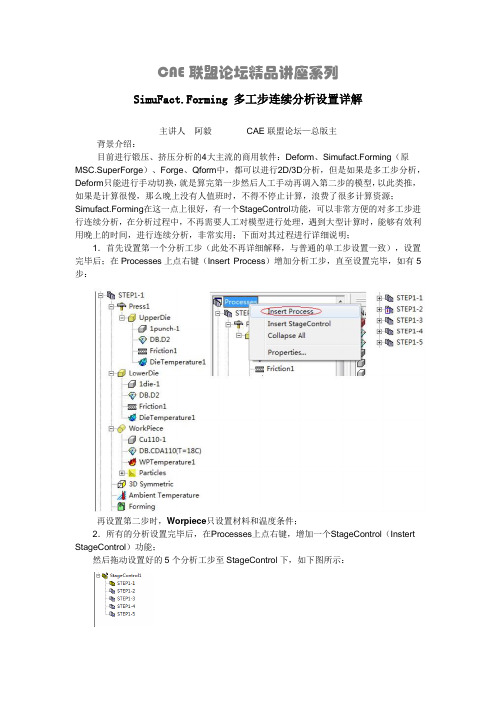
1.首先设置第一个分析工步(此处不再详细解释,与普通的单工步设置一致),设置完毕后;在Processes上点右键(Insert Process)增加分析工步,直至设置完毕,如有5步:
再设置第二步时,Worpiece只设置材料和温度条件;
2.所有的分析设置完毕后,在Processes上点右键,增加一个StageControl(Instert StageControl)功能;
然后拖动设置好的5个分析工步至StageControl下,如下图所示:
默认情况下,STEP1计算完毕后,会自动的将Workpiect工件自动的设置到STEP2中,如果还需要DIE,请在step2以下工步上点右键,选择所需要的模具
所有设置完毕后,在Stage Control上点右键,进行多工步计算;。
锻造仿真软件simufact.forming公司介绍
锻造仿真软件simufact.forming公司介绍先进和便捷的⾦属成形仿真系统 ——simufactSimufact软件介绍内容usimufact发展历程u⾦属塑性成形模拟技术 u usimufact功能介绍软件应⽤实例⼀、产品发展历程Simufact Engineering Gmbhu u u u u u usimufact是世界知名的CAE公司,总部位于德国成⽴于1995年,软件开发团队不断发展与壮⼤ 1995年成为MSC和MARC公司的商业合作伙伴致⼒于⾦属成形和制造⼯艺仿真不断加强与⼤学和⾏业组织的合作⽬前已成为四个国际⾦属加⼯协会的会员超过10年的软件开发、销售、培训以及客户⽀持经验Balve Marburg FuldaHamburgKasselSimufact 发展历程Release nubering:1.02.03.04.05.06.07.08.01996MARC/ Autoforge 1.21998 1999 2000 2001 2002 2003MSC.SuperForm 2002 MSC.SuperForm 2003 MSC.SuperForm 20042005 2006 2007simufact.forming Release 8.0MARC/ Autoforge 2.2 MSC/ Autoforge 2.3 MSC/ Autoforge 3.1MSC.Manufacturing 2005Superforge x.y Superforge u.vMSC.SuperForge 2004 MSC.SuperForge 2003MSC.SuperForge 2002MARC/ MSC MARC/ MSC Merger Mergerrenaming renaming Autoforge AutoforgeMSC.Manufacturing MSC.Manufacturinglicense license combining combining产品核⼼技术Simulating Manufacturingreal integrated solution of … MSC.SuperForm MSC.Marc MSC.SuperForge MSC.Dytran产品模块l l l l l l l l⾦属成形⼯艺模拟环境机械连接⼯艺仿真模块焊接⼯艺仿真模块材料数据库模拟结果分析⼯模具载荷分析⽹格划分模块机构运动模块⾦属成形模拟是simufact的最主要模块 (锻造、轧制、拉拔、挤压、冲压)Simufact 软件适⽤的领域u⾦属成形⼯艺分析包括锻造、轧制、旋压、挤压、拉拔、剪切等体积成形⼯艺和板料成形⼯艺,同时也可以进⾏变形和传热的耦合分析,例如热成形或温成形⼯艺、以及材料的加热和冷却过程。
- 1、下载文档前请自行甄别文档内容的完整性,平台不提供额外的编辑、内容补充、找答案等附加服务。
- 2、"仅部分预览"的文档,不可在线预览部分如存在完整性等问题,可反馈申请退款(可完整预览的文档不适用该条件!)。
- 3、如文档侵犯您的权益,请联系客服反馈,我们会尽快为您处理(人工客服工作时间:9:00-18:30)。
simufact.forming9.0
—实例分析教程
锻造
段小亮2010年1月北京
e-mail:simuate@
1. 创建一个新的工艺仿真
通过开始菜单或桌面快捷方式打开simufact.forming软件。
在软件界面点击File下拉菜单中的New Project,或者通过快捷键Ctrl+N来创建一个新的工艺仿真。
或者通过点击新建图标来创建一个新的工艺仿真。
点击后会弹出如下Process Properties对话框:
这里可以设置仿真相关参数:锻造类型(热/冷)、仿真类型(2D/3D)、和求解器(有限元/有限体积)。
当选择完工艺类型后,系统将自动定义相关参数。
下面可以选择模具数量。
操作步骤:
左侧选择工艺类型为Open Die(开式模锻),修改锻造类型为Hot
保留缺省设置(3D和FV)
点击ok确认
2. 仿真建模
确认后,你可以看到simufact.forming软件已经自动设置好了仿真所需要的相关参数。
在左侧可以看到仿真所需要的进程树,右侧为预览窗口。
鼠标左键缓慢双击要修改名称的进程树,或者通过右键单击选择Rename可以修改名称。
3 导入几何模型
导入模具和坯料的几何模型有两种方式:
1、在菜单栏点击Insert —Model —Form file/CAD import
2、下图所示第二个空白区(备品区)点击鼠标右键Model —Form file/CAD
import
解释:
Form file:一般导入通用有限元格式,如STL、BDF、DA T、ARC、T16、WRL 和DXF。
CAD import:可以直接打开proe、catia、ug、SolidWorks等默认格式文件,无需转换。
选择Form file导入STL格式文件,例子中要用到的文件我上传到附件中了。
在弹出的对话框中选中如下三个文件:Lower.stl、Billet.stl、Upper.stl,点击“打开”
选择单位为:mm
在备品区用鼠标左键拖动Lower、Billet、Upper到左侧进程树对应模具和坯料中
拖动后在右侧图形区会出现图示几何模型。
点击切换鼠标功能按钮,切换鼠标功能,点击按钮,将鼠标功能切换
为移动功能,点击,限定只能沿Z轴移动。
在进程树中选中upperdie(上模)。
在右侧图形区,按住鼠标左键拖动上模和下模分开。
拖拉完毕后,再次点击切换鼠标功能按钮,切换鼠标功能。
在进程树workpiece上点击鼠标右键选择Align BoundingBox。
在弹出的对话框中间选择LowerDie,意为:使坯料向下模以一定方式靠近。
点击上部和下部Center按钮,选择坯料和下模的参考点均为中心点,使坯料的中心点和下模的中心点重合。
点击ok。
点击切换鼠标功能按钮,切换鼠标功能,点击按钮,将鼠标功能切换
为移动功能,点击,限定只能沿Z轴移动。
在进程树中选中workpiece(坯料)。
在右侧图形区,按住鼠标左键拖动坯料至上模和下模中间位置。
同理,使用拖拉方式,将坯料限定在X方向移动,在进程树中选中上模,
点击工具栏透明图标,隐藏上模。
使其移动到如下图所示位置。
在进程树中选中workpiece,点击菜单栏Tools,在下拉菜单中选择Positioner。
在弹出的坯料位置自动确定对话框中,选择坯料自由下落方向为Z,点击向下的箭头。
坯料自动落到下模上面。
如图所示。
4 定义材料
模具材料的定义:如果不定义模具材料,缺省设置为H13模具钢,同样在备品区点击鼠标右键,出现如下图菜单,选择Material-Library
在材料数据库中选择Steel—DIN_1.7131 (16MnCrS5),点击Load,所选材料出现在右侧备品区。
点击Close关闭材料数据库对话框。
将备品区所选DIN_1.7131材料通过鼠标左键拖拽到左侧进程树Workpiece 下方。
5 定义压力机
右键在备品区单击,选择Press —Manual,弹出如下对话框,选择Crank press (曲柄压力机)并定义相关参数如下图所示:
然后将所定义的压力机press1在备品区通过鼠标拖拽到进程树中。
然后再将上模拖拽到press1下面
6 定义摩擦
在备品区点击鼠标右键,或者通过Insert —Friction —Manual插入摩擦类型,选择Coulomb Friction and Plastic Shear Friction,定义摩擦因子等相关参数图如下图所示,然后点击OK。
将定义好的摩擦通过鼠标拖拽到进程树中的上模和下模上。
如图
7 定义温度
在进程树中用鼠标左键双击Ambient Temperature设定温度为50℃。
在备品区点击右键或者点击菜单Insert —Heat —Die —Manual设置模具温度,相关参数设定如下:
同样Heat —WorkPiece设置坯料温度,相关设置如下:
将模具温度和坯料温度拖拽到左侧进程树对应处,如下图所示:
8 其它控制参数设置
点击菜单栏Tools,在下拉菜单中选择Define Point。
弹出定义点的对话框。
用鼠标在右侧图形区选中上模模面上的一点。
点击定义点对话框中的Add (添加下一点),在右侧图形区选中下模模面上一点,再点击Add,点击Close 退出。
在进程树中左键双击Forming,出现如下工艺过程相关参数定义对话框。
点击按钮,使用前面定义的两点确定压力机行程。
在弹出的对话框中,分别选择前面定义的两个点,在Distance at 100% stroke
处输入2。
意为:压力机达到最大行程时,两个点之间的距离,这里也就是上下模之间的距离。
点击ok返回。
其它设置采取默认设置,点击Start按钮可查看模具运动是否正确,如果正确,点击确定后退出。
在Element Sizes菜单中可以调整坯料在通过优先体积法计算时,单元的边长。
如下图所示,入选中Show FV in Pre,则在右侧图形区可以看到所划分外表面单元的大小。
下面两个图是分别选择单元尺寸为10和5时所划分的单元格对比。
在仿真中,我们根据实际需要选择单元大小。
9 提交运行
点击确定。
返回主页面。
点击下方运行工具栏运行图标弹出工作提交对话框,点击yes即可开始计算。