4-20mA输出电流传感器BA系列说明书
Baela温控器说明书翻译

Baelz自动化控制器第一页操作指南微处理器——基于控制器ucelsitron baelz 6490/baelz 6590通用型三位——步控制器带有特殊的PID逐级控制器计算工业控制器操作简单使用者定义操作级过程参数与设定值数字显示PI和PID控制结构两位控制3位控制Pt100,电流和电压信号的测量输入手动/自动转换紧凑设计96㎜×96㎜×135㎜2个可调的设定值遥控设定值设定值斜线上升通过数字输入进行控制串行接口强大的自我优化数据保护的半导体记忆插入式接线端保护级别Front 1P65紧凑设计 48㎜×96㎜×140㎜目录第二页1.功能简介2.操作与设置2.1在自动模式下设定值2.2手动模式下打开/关闭执行元件2.3参数/结构级分支2.4第二操作级分支(使用者定义操作级)2.5设定参数/结构点3.参数化/结构级3.1优化:自动决定有利的控制参数3.2比例带Pb3.2.3位控制器3.3积分作用时间tn3.3.1双位控制器3.4微分作用时间3.5死区3.6动作时间/阀门起动时间3.7报警(649010/01/2和659010/1/2)3.8报警继电器(在6490/3/4/5和6590/3/4/5)3.9 LED显示小数点3.10过程变量显示PV缩放3.11设定值限值3.12遥控/本地转换(6490/1/2/5和6590/1/2/5)3.13第二定值SP2(6490/2/3/4和6590/2/3/4)3.14定值斜线变化Spr3.15定值斜线变化趋势3.16过程增益P.G3.17过程变量PV的输入(输入PV)3.18遥控定值的输入(输入SP)(6490/1/2/5和6590/1/2/5)3.19进程变量PV的测量值过滤器3.20对传感器故障PV的应答(传感器断开)3.21自动/手动转换互锁3.22控制器动作趋势3.23数字化输入(开始、关闭、停止)的功能(6490/3/4和6590/3/4)3.24串行接口传输速度(6490/3/4和6590/3/4)3.25串行接口地址/名称(6490/3/4和6590/3/4)3.26串行通信(6490/3/4和6590/3/4)3.27第二操作级(操作级2)3.28参数/结构级访问(密码)4.安装5.电力连接5.1线路图6.试运转/试车7.技术参数8.订货号码baelz 6490/baelz /65909.参数/结构级,数据列表总览警告:在电力设备操作中,部分元件与高压相联的危险性是不可避免的。
华氏12012线性4-20mA输出温度传感器说明书

To Order (Specify Model Number)
Model No.
Price Description
Applications
OS1611(*)-(**) OS1711(*)-(**) OS1811(*)-(**)
$ 930 1125 1850
Remote IR sensing head and electronics
Shown smaller than actual size.
OS1700 Series sensor with integral electronics.
ߜ Linear 4 to 20 mA Output
ߜ Simple 2-Wire Installation
ߜ 10 to 40 Vdc Power Operation
ߜ 3 Models to Choose From
ߜ 6 Infrared Spectral Responses
OS1800 Series sensor with integral electronics/display.
OS1600 Series OEM style sensor and remote electronics.
J-95
RUGGED!
INDUSTRIAL!
Rear view showing sensor.
J
OS1811-112-S, $1600, shown actual size.
signal allows the sensor to be interfaced with a variety of remote devices: indicators, controllers, recorders, and/or computers, etc.
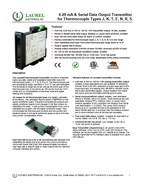
莱瑞尔电子有限公司4-20毫安埃与串行数据输出传感器说明书

LAURELELECTRONICS, INC.4-20 mA & Serial Data Output Transmitter for Thermocouple Types J, K, T, E, N, R, SFeatures• 4-20 mA, 0-20 mA, 0-10V or -10V to +10V transmitter output, 16 bits, isolated • RS232 or RS485 serial data output, Modbus or Laurel ASCII protocol, isolated • Dual 120 mA solid state relays for alarm or control, isolated• Factory calibrated for thermocouple types J, K, T, E, N, R, S in one range • User selectable input span from entire thermocouple range down to 15.0° • Output update rate to 60/sec• Analog output resolution 0.0015% of span (16 bits), accuracy ±0.02% of span • 5V, 10V or 24V dc transducer excitation output, isolated• Universal 85-264 Vac / 90-300 Vdc or 10-48 Vdc / 12-32 Vac power•DIN rail mount housing only 22.5 mm wide, detachable screw-clamp connectorsDescriptionThe Laureate thermocouple transmitter provides a linearized, highly accurate, stable and repeatable transmitter output forthermocouple types J, K, T, E, N, R or S. The thermocouple type and temperature range, specified in °C or °F, are user-selectable. The temperature range can be as wide as the entire span of the thermocouple type, or as narrow as 150 counts (such as 15.0°), limited only by considerations of electrical noise and digital filtering time constants.All ranges for all thermocouple types are digitally calibrated at the factory, with calibration factors stored in EEPROM on the signal conditioner board. This allows temperatures sensors and signal conditioner boards to be changed in the field without re-calibrating the meter. A cold junction compensation (CJC) unit is calibrated as a system with the signal conditioner board. That unit encloses the thermocouple junctions and the junction tem-perature sensor in the same isothermal space so as to minimizecold junction compensation errors.Fast read rate at up to 50 or 60 conversions per second while integrating the signal over a full power line cycle is provided by Concurrent Slope (Pat 5,262,780) analog-to-digital conversion. High read rate is ideal for peak or valley capture and for real-time computer interface and control.Standard features of Laureate transmitters include:• 4-20 mA, 0-10V or -10V to +10V analog transmitter output,isolated, jumper-selectable and user scalable. All selections provide 16-bit (0.0015%) resolution of output span and 0.02% output accuracy of a reading from -99,999 to +99,999 counts that is also transmitted digitally. Output isolation from signal and power grounds eliminates potential ground loops. • Serial communications output, isolated. User selectableRS232 or RS485, half or full duplex. Three protocols are user selectable: Modbus RTU, Modbus ASCII, or Laurel ASCII. Modbus operation is fully compliant with Modbus Over Serial Line Specification V1.0 (2002). The Laurel ASCII protocol allows up to 31 Laureate devices to be addressed on the same RS485 data line. It is simpler than the Modbus protocol and is recommended when all devices are Laureates. • Dual solid state relays, isolated. Available for local alarm or control. Rated 120 mA at 130 Vac or 170 Vdc. • Universal 85-264 Vac power. Low-voltage 10-48 Vdc or12-32 Vac power is optional.Easy Transmitter programming is via Laurel's Instrument Setup Software, which runs on a PC under MS Windows. This software can be downloaded from our website at no charge. The required transmitter-to-PC interface cable is available from Laurel (P/N CBL04).SpecificationsTC Types Range Conformity Error J -210°C to +760°C (-347°F to +1400°F) ±0.09°C (±0.16°F)K -244°C to +1372°C (-408°F to +2501°F) ±0.1°C (±0.17°F)T0°C to +400°C (32°F to 752°F)-257°C to 0°C (-430°F to +32°F)±0.03°C (±0.05°F)±0.2°C (±0.36°F)E -240°C to +1000°C (-400°F to +1830°F) ±0.18°C (±0.32°F)N -245°C to +1300°C (-410°F to +2370°F) ±0.10°C (±0.17°F) R -45°C to +1768°C (-49°F to +3214°F) ±0.17°C (±0.31°F) S -46°C to +1768°C (-51°F to +3213°F) ±0.12°C (±0.22°F) Analog InputCalibrationInput Resistance & Current Max Lead Resistance Overall Error at 25°C Span TempcoRef Junction Tempco Over-Voltage Protection NMR at 50/60 HzCMR, DC-60 HzCMV, DC-60 HzOpen sensor indication NIST Monograph 125 (IPTS-68)1 GΩ, 100 pA1 kΩ max for rated accuracy±0.01 of full scale ±2 counts±0.003% of reading/°C±0.02 deg/deg125 Vac80 dB plus selectable filter from 80 ms to 9.6 s time constant 120 dB with 500Ω imbalance250 Vac from power and earth grounds0 mA or > 20 mA output, selectableAnalog Output (standard)Output Levels Compliance at 20 mA Compliance at 10V Output Resolution Output ErrorOutput Isolation Step response time 4-20 mA, 0-20 mA, 0-10 Vdc, -10 to +10Vdc (user selectable) 10V ( 0-500Ω load )2 mA ( 5 kΩ load or higher)16 bits (65,536 steps)±0.02% of output span ± overall input error250V rms working, 2.3 kV rms per 1 minute test50 msDual Relay Output (standard)Relay Type Load Rating Two solid state relays, SPST, normally open, Form A 120 mA at 140 Vac or 180 VdcSerial Communications (standard)Signal TypesData RatesOutput Isolation Serial Protocols Modbus Modes Modbus Compliance Digital Addressing RS232 or RS485 (half or full duplex)300, 600, 1200, 2400, 4800, 9600, 19200 baud250V rms working, 2.3 kV rms per 1 min test Modbus RTU, Modbus ASCII, Laurel ASCIIRTU or ASCIIModbus over Serial Line Specification V1.0 (2002) 247 Modbus addresses.Up to 32 devices on an RS485 line without a repeaterPower InputStandard Power Low Power Option Power Frequency Power Isolation Power Consumption 85-264 Vac or 90-300 Vdc10-48 Vdc or 12-32 VacDC or 47-63 Hz250V rms working, 2.3 kV rms per 1 min test 2W typicalMechanicalDimensions MountingElectrical Connections 129 x 104 x 22.5 mm case35 mm rail per DIN EN 50022 Plug-in screw-clamp connectorsEnvironmentalOperating Temperature Storage Temperature Relative Humidity Cooling Required 0°C to 55°C-40°C to 85°C95% at 40°C, non-condensingMount transmitters with ventilation holes at top and bottom. Leave 6 mm (1/4") between transmitters, or force air with a fan.PinoutMechanicalOperation as a Fast ON/OFF Controller or Supervisory MonitorWith the optional dual solid state relay output option, which has a typical response time of only 17 ms, Laureate temperature meters and transmitters can serve as extremely fast and accurate ON/OFF con-trollers for closed-loop temperature control. They can also serve as supervisory process monitors and provide alarms or shutoffs when processes exceed normal limits. Multiple setpoint operating modes are individually selectable for each relay. Relay duty cycles and chatter can be minimized with programmable hysteresis and time delays. A band deviation operating mode can be selected for each relay, where an alarm is generated whenever the reading is a selected number of counts above or below the setpoint. The relay modes are non-latching.Ordering GuideCreate a model a model number in this format: LT20JCTransmitter Type LT Laureate 4-20 mA & RS485 TransmitterMain Board2 Standard Main BoardPower0 Isolated 85-264 Vac or 90-300 Vdc1 Isolated 10-48 Vdc or 12-32 VacThermocouple Input JC Thermocouple Type J, -210°C to 760°CJF Thermocouple Type J, -347°F to 1400°FKC Thermocouple Type K, -347°C to 1372°CKF Thermocouple Type K, -408°F to 2501°FTC Thermocouple Type T, -257°C to 400°CTF Thermocouple Type T, -430°F to 752°FEC Thermocouple Type E, -240°C to 1000°CEF Thermocouple Type E, -400°F to 1830°FNC Thermocouple Type N, -240°C to 1000°CNF Thermocouple Type N, -410°F to 2370°FSC Thermocouple Type S, -46°C to 1768°CSF Thermocouple Type S, -51°F to 3214°FR C Thermocouple Type R, -45°C to 1768°CRF Thermocouple Type R, -49°F to 3213°FNote: The same signal conditioner board can be user configured for all thermocouple types listed and °C or °F.Accessories CBL04RS232 cable, 7ft. Connects RS232 screw terminals of LT transmitter to DB9port of PC.CBL02U SB to RS232 adapter cable. Combination of CBL02 and CBL04 connectstransmitter RS232 terminals to PC USB port.。
流量计说明书

流量计说明书流量计说明书篇一:流量计使用方法及问题解析流量计外观及使用方法如下所示:接线时1,2,3是电源端使用的是24V供电4是数字量输出,也就是说该引脚输出一定频率的信号,信号的频率与流量相关。
频率关系为1HZ的频率对应一单位NV的的流量(该单位不是清楚是什么)5是模拟量输出,输出的是4-20mA的电流信号,电流大小与流量线性相关。
6、7是RS232串口输出,RXD接收端,TXD发送端。
该端口可以提供与PC的通信功能,也就对应需购买的软件。
连接方式为RX对应9针串口(电脑端口)的2,TX对应9针串口的3,GND 对应9针串口的5。
问题分析及解决方法1、流量计自带LCD屏显示功能,如果不能正常显示说明,电源未正确连接,检查123接线是否正确。
2、如未配液晶屏,需购买。
或通过3条中模拟量或数字量的自制显示单元实现(成本不会很高)3、如果正常显示,流量数显示不正确,说明参数未配置正确 1是输出流量没规律,说明流量计是坏的,需更换2输出线性相关只是大小不正确可通过以下方式解决1)通过串口发送命令对传感器重新标定或设定,但是通信协议需厂家提供。
厂家提供的软件不一定有该功能。
2)通过模拟量输出口,测量输出电流,然后将电流与流量相对应,对应关系可自己设定。
自己做一个小控制器通过这个关系将流量重新显示。
3)通过数字量口,测量频率信号,然后对应流量信号,也需要自己做控制器显示。
4、另一种可能是测量程不匹配,可参照下表确认,内径与最大最小流量的关系流量计说明书篇二:超声波流量计说明书SCT超声波流量计说明书(固定式、便携式通用)MKflo-2000F系列中文版超声波流量计说明书目录一概述 (4)1.1 引言 (4)1.2 SCT的特点 (4)1.3 工作原理 (4)1.6 可选备件 (5)1.7产品型号编码规则 (5)1.8接线图 (6)1.9 性能指标 (6)二开始安装测量 (8)2.1 开箱检查 (8)2.2 供电电源 (8)2.2.1 便携式 (8)2.2.2 固定式 (8)2.2.3 接线 (8)2.3 通电 (8)2.4 键盘 (8)2.5 怎样操作 (9)2.6 窗口简介 (10)2.7 快速输入管道参数和步骤 (10)2.8选择测量点 (11)2.9 探头接线 (11)2.10 安装探头 (12)2.10.1 探头安装距离 (12)2.10.2 探头安装方式 (12)2.10.3 V法 (12)2.10.4 Z法 (12)2.10.5 N法(不常用的方法) (13)2.10.6 W法(极不常用的方法) (13)2.10.7 插入式传感器的安装 (13)2.11 检查安装 (17)2.11.1 信号强度 (17)2.11.2数据数量 (18)2.11.3 总传输时间、时差 (18)2.11.4 传输时间比 (18)2.11.4 安装时注意的问题 (18)三怎样使用 (19)3.1 怎样判断流量计是否工作正常 (19)3.2 怎样选择流量单位制 (19)3.3 怎样选择瞬时流量单位 (19)3.4 怎样选择累积流量单位 (19)3.5 怎样选择累积器倍乘因子 (19)3.6 怎样打开或关闭流量累积器 (19)2MKflo-2000F系列中文版超声波流量计说明书3.7 怎样实现流量累积器清零 (19)3.8 怎样恢复出厂设置 (19)3.9 怎样使用阻尼器稳定流量显示 (20)3.10 怎样使用零点切除避免无效累积 (20)3.11 设置零点提高测量精度 (20)3.12 修改仪表系数(标尺因子)进行标定校正 (20)3.13 密码保护(加锁与开锁) (20)3.14 怎样使用打印机 (21)3.15 怎样使用4~20mA电流环输出 (21)3.16 怎样输出模拟电压信号 (21)3.17怎样输出累积脉冲 (21)3.18 怎样使用OCT输出 (21)3.19 怎样修改日期时间 (21)3.20 怎样调整LCD显示器 (22)3.21 怎样使用RS232串行口 (22)3.22怎样查看每日、每月、每年流量 (22)3.23 怎样对模拟输出进行校准 (22)3.24 查看电子序列号和其他细节 (22)四命令/显示窗口详解 (23)4.1 显示窗口一览表 (23)4.2 显示窗口顺序介绍 (24)五问题处理 (41)表1. 硬件上电自检信息及原因对策 (41)表2. 工作时错误代码原因及对策 (42)其他常见问题问答 (43)六热量和其他物理量测量 (44)6.1 功能介绍 (44)6.2热量测量硬件接线 (44)6.3怎样进行热量测量 (44)6.4温度、压力等信号的量程范围设置 (44)6.5联网时模拟输入量的读取 (44)七质量保证及服务维修支持 (45)7.1 质量保证 (45)7.2 公司服务 (45)7.3 产品升级 (45)7.4 技术咨询 (45)八附录 (46)8.1常用液体声速和粘度 (46)8.2 常用材料声速 (46)8.3水中声速表(1标准大气压下) (47)3MKflo-2000F系列中文版超声波流量计说明书一概述1.1 引言欢迎您选择使用性能更优异、功能更多、采用专利技术制造的MKFLO-2000F系列中文版超声波流量计。
ueonline 4-20mA 信号输出 压力变送器 说明书

安装维护前,请先通读说明书,并参阅最后一页推荐的操作、保修、厂家责任。
概述误用或错用此产品可能导致危险,在安装使用前请仔细阅读此说明书。
认证编号 2020322304003036适用范围中国标识 Ex d IIC T6 Gb; Ex tD A21, IP66 T85°C应用标准GB 3836.1, GB3836.2, GB 12476.1, GB 12476.5认证编号 DEMKO 09 ATEX 0815573X 适用范围 欧洲 (EU)标识 II 2 G Ex db IIC T6 Gb; II 2 D Ex tb IIIC T85°C Db IP66 应用标准EN IEC 60079-0; EN 60079-1; EN 60079-31认证编号 IECEx UL 03.0001X适用范围 国际标识 Ex db IIC T6 GbEx tb IIIC T85°C Db IP66-40°C to +75°C 应用标准IEC 60079-0; IEC 60079-1; IEC 60079-31认证编号 DEMKO 11 ATEX 1105261X 适用范围 欧洲(EU)标识 II 1 G Ex ia IIC T6 Ga应用标准EN IEC 60079-0; EN 60079-11认证编号 IECEx UL 14.0075X 适用范围 国际标识 Ex ia IIC T6 Ga-50°C ≤ Tamb ≤ +60°C 应用标准IEC 60079-0; IEC 60079-11有关标准修订/版本号,请参考UE 网站上的实际证书(如DEMKO 09 ATEX 0815573X ):https:///resource-center/certifications/安装前,先确认所选开关接液部件是否与所测介质兼容。
为防止危险环境着火,在打开前断开电源电路。
施耐德楼宇自控产品 BA系统资料

施耐德楼宇自控产品5.1、中央监控软件Vista 5 Standalone提供顺序控制程序、功能联锁程序、用电管理程序、照明控制程序、维修记录程序、统计程序、报表产生程序和历史数据与处理等程序。
系统平台应按实时、多用户和多进程对资源进行分配和管理,系统将拥有事件驱动顺序以及优先结构装置,以便于系统能在同一时间里处理实时情况与紧急任务。
同时,系统平台还具备网络管理、标准网络协议、远程通信管理以及符合计算机技术发展趋势的要求。
软件按模块形式设计,除具备基本功能外,还能提供各种丰富的应用开发功能,例如:OPC、DDE、ODBC等,以利于程序的开发、扩展和修改,支持Lontalk协议,符合有关国际标准和国家标准。
用户界面全部汉化,具备多窗口功能、动态图形显示并且操作直观、简便。
5.2、OPC服务包OPC Client/Sever用于冷热源及变配电系统的集成。
利用定制数据访问,对数据库的数据点进行读/写,从而与OPC Server进行通讯,通过报警接口,接收OPC Server中的报警和事件。
5.3、通讯接口卡PCLTA-21 PCI-card, FTT10LonTalk适配卡、TP/FT-10、通讯速率为78kbps5.4、通讯中继器TAC Xenta Repeater⏹Lonworks网络中继器,用来将网络信号放大,但不会给通讯带来影响。
⏹供电电压24VAC±20%,50-60HZ或19-40VDC,8-28VAC,50/60HZ或8-40VDC⏹功率:最大1.5W⏹环境温度:存储(-20到75摄氏度),运行(0到75摄氏度),湿度(最大90%RH,无冷凝)⏹防护等级IP20⏹中继器数量:任何两个路由器之间最多一个5.5、通讯终端模块LTM网络终端模块,lonworks FTT105.6、直接数字控制器TAC Xenta 401:C⏹微处理器为基础的可编程DDC,CPU采用32位,12.28MHZ 2MB flash memory ,128KB SRAM,最大50条趋势记录,时间表,报警,PID运算控制, DDC通讯符合LonMark标准,并具有lonmark认证标志,具有可脱离中央控制主机独立运行和联网运行能力,最大可支持15个I/O模块。
ATControls 4-20mA 转位传感器安装与维护手册说明书

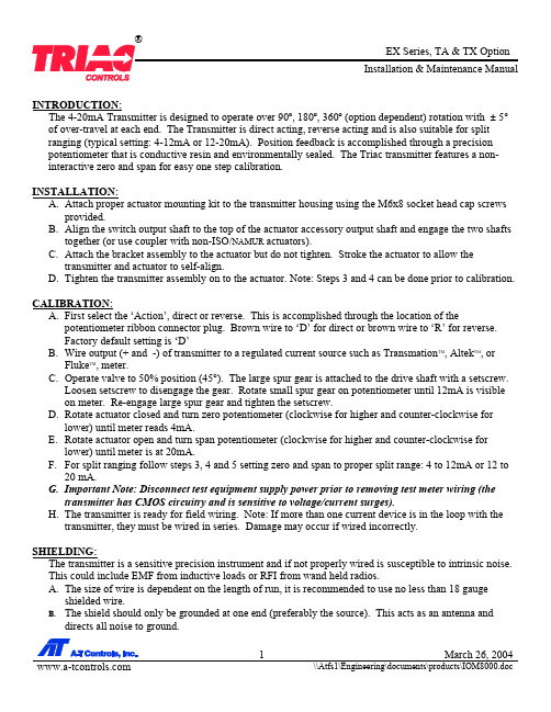
INTRODUCTION:The 4-20mA Transmitter is designed to operate over 90º, 180º, 360º (option dependent) rotation with ± 5° of over-travel at each end. The Transmitter is direct acting, reverse acting and is also suitable for split ranging (typical setting: 4-12mA or 12-20mA). Position feedback is accomplished through a precision potentiometer that is conductive resin and environmentally sealed. The Triac transmitter features a non-interactive zero and span for easy one step calibration.INSTALLATION:A.Attach proper actuator mounting kit to the transmitter housing using the M6x8 socket head cap screwsprovided.B.Align the switch output shaft to the top of the actuator accessory output shaft and engage the two shaftstogether (or use coupler with non-ISO/NAMUR actuators).C.Attach the bracket assembly to the actuator but do not tighten. Stroke the actuator to allow thetransmitter and actuator to self-align.D.Tighten the transmitter assembly on to the actuator. Note: Steps 3 and 4 can be done prior to calibration. CALIBRATION:A.First select the ‘Action’, direct or reverse. This is accomplished through the location of thepotentiometer ribbon connector plug. Brown wire to ‘D’ for direct or brown wire to ‘R’ for reverse.Factory default setting is ‘D’B.Wire output (+ and -) of transmitter to a regulated current source such as Transmation TM, Altek TM, orFluke TM, meter.C.Operate valve to 50% position (45°). The large spur gear is attached to the drive shaft with a setscrew.Loosen setscrew to disengage the gear. Rotate small spur gear on potentiometer until 12mA is visible on meter. Re-engage large spur gear and tighten the setscrew.D.Rotate actuator closed and turn zero potentiometer (clockwise for higher and counter-clockwise forlower) until meter reads 4mA.E.Rotate actuator open and turn span potentiometer (clockwise for higher and counter-clockwise forlower) until meter is at 20mA.F.For split ranging follow steps 3, 4 and 5 setting zero and span to proper split range: 4 to 12mA or 12 to20 mA.G.Important Note: Disconnect test equipment supply power prior to removing test meter wiring (thetransmitter has CMOS circuitry and is sensitive to voltage/current surges).H.The transmitter is ready for field wiring. Note: If more than one current device is in the loop with thetransmitter, they must be wired in series. Damage may occur if wired incorrectly.SHIELDING:The transmitter is a sensitive precision instrument and if not properly wired is susceptible to intrinsic noise.This could include EMF from inductive loads or RFI from wand held radios.A.The size of wire is dependent on the length of run, it is recommended to use no less than 18 gaugeshielded wire.B.The shield should only be grounded at one end (preferably the source). This acts as an antenna anddirects all noise to ground.TROUBLESHOOTING:1. Problem:Output not continuous throughout actuator/valve stroke (experience a band of max. output).Probable Cause/Solution:Potentiometer out of adjustment (see calibration steps 3 through 9).2. Problem:Transmitter does output 4 or 20mA at desired end of travel.Probable Cause/Solution:Zero or span trim potentiometer is out of adjustment (see calibration steps 4 and 5).3. Problem:Transmitter module has no current signal or provides a constant signal.Probable Cause/Solution:Circuit Board LED not lit:1. Loose or shorted signal connection (no loop power)2. Controller board not responding (replace board).3. Check control sourceCircuit Board LED lit:1. Potentiometer disengaged2. Defective potentiometer or controller board (replace).3. Check control source.SPECIFICATIONS:OHM10KPotentiometer30VDC–12VoltageSupplyLinearity ± 0.5% of full scaleDeadband ± 0.25% of full scaleHysterisis&Action Direct or ReverseZero – Span 20 Turn Trim Potentiometer (Non-interactive)CMOS-ASICLogic/ProcessorA-T Controls products when properly selected, is designed to perform its intended function safely during its useful life. However, the purchaser or user of A-T Controls products should be aware that A-T Controls products might be used in numerous applications under a wide variety of industrial service conditions. Although A-T Controls can provide general guidelines, it cannot provide specific data and warnings for all possible applications. The purchaser / user must therefore assume the ultimate responsibility for the proper sizing and selection, installation, operation, and maintenance of A-T Controls products. The user should read and understand the installation operation maintenance (IOM) instructions included with the product, and train its employees and contractors in the safe use of A-T Controls products in connection with the specific application.While the information and specifications contained in this literature are believed to be accurate, they are supplied for informative purposes only. Nothing contained in this literature should not be considered certified or as a guarantee of satisfactory regarding any matter with respect to this product. Because A-T Controls is continually improving and upgrading its product design, the specifications, dimensions and information contained in this literature are subject to change without notice. Should any question arise concerning these specifications, the purchaser / user should contact A-T Controls.For more information about A-T ControlsFor product specifications go to /A-T Controls, Inc.11363 Deerfield RoadCincinnati, OH 45242Phone: (513) 530-5175Fax: (513) 247-5462。
安科瑞BA系列交流电流传感器安装使用说明书

022BA系列交流电流传感器安装使用说明书V1.4安科瑞电气股份有限公司联系方式:188****5116(微信同号)申明版权所有,未经本公司之书面许可,此手册中任何段落,章节内容均不得被摘抄、拷贝或以任何其它形式复制、传播,否则一切后果由违者自负。
本公司保留一切法律权利。
本公司保留对本手册所描述之产品规格进行修改的权利,恕不另行通知。
订货前,请垂询当地代理商以获悉本产品的最新规格。
目录1产品概述 (1)2型号说明 (1)3通用技术条件 (2)4产品规格 (2)4.1BA05-AI交流电流传感器 (2)4.2BA10-AI交流电流传感器 (3)4.3BA20-AI交流电流传感器 (3)4.4BA50-AI交流电流传感器 (4)5外型及安装 (4)5.1外形及穿孔尺寸 (2)5.1.1BA05-AI交流电流传感器 (4)5.1.2BA10-AI交流电流传感器 (5)5.1.3BA20-AI交流电流传感器 (5)5.1.4BA50-AI交流电流传感器 (5)5.2安装方法 (6)5.3应用实例 (7)6BA50L交流剩余电流传感器 (8)6.1BA50L-AI/I(V)交流剩余电流传感器 (8)6.2BA50L-AI变流剩余电流传感器外型及安装 (8)6.3应用实例 (9)6.3.1单相回路 (9)6.3.2三相三线回路 (10)6.3.3三相四线回路 (11)7接线方式 (12)8订货范例 (13)BA系列产品应用电磁感应原理,对电网中的交流电流进行实时测量,采用恒流和线性补偿技术,将其隔离变换为标准的直流信号输出。
24伏或12伏安全电压供电,可广泛用于工业自动化领域。
BA50L为变流剩余电流互感器主要检测用电系统的漏电流,能随时掌握电气线路和设备的情况,防止因漏电而发生的火灾等事故。
2型号说明BA—/—类型:无——平均值测量T——真有效值测量输出:I——直流电流V——直流电压输入:AI——交流电流穿孔尺寸:(单位:mm)05-φ510-φ1020-φ2050-φ50产品系列代号3通用技术条件电源电压DC12V或24V 功耗≤1W绝缘电阻>100MΩ耐压强度输入/输出、电源之间2.0KV/1min,50Hz 温度系数-10℃~+55℃时,≤400ppm/℃环境温度工作:-10℃~+55℃储存:-25℃~+70℃湿度≤93%RH,不结露,无腐蚀性气体场所海拔≤2000m安装方式TS35导轨,或用螺钉固定柜体上4.1BA05-AI交流电流传感器BA05-AI/I(V)单相交流电流传感器(平均值法测量)BA05-AI/I(V)-T单相交流电流传感器(真有效值法测量)技术参数指标精度等级0.5级输入标称值电流AC0.5A、5A、10A等AC0~(0.5~10A)过载持续1.2倍,瞬时电流10倍/5秒吸收功率≤1VA频响25Hz~800Hz(平均值),25~5kHz(真有效值),特别适合工频场合输出标称值DC4~20mA,或0~20mA,0~5V,0~10V等负载电阻电流输出时≤500Ω,电压输出时≥1KΩ响应时间平均值≤350ms,真有效值≤150ms4.2BA10-AI交流电流传感器BA10-AI/I(V)单相交流电流传感器(平均值法测量)BA10-AI/I(V)-T单相交流电流传感器(真有效值法测量)技术参数指标精度等级0.5级输入标称值电流AC8A、25A、50A等AC0~(8~50)A过载持续1.2倍,瞬时电流10倍/1s秒吸收功率≤1VA频响25Hz~800Hz(平均值),25~5kHz(真有效值),特别适合工频场合输出标称值DC4~20mA,或0~20mA,0~5V,0~10V等负载电阻电流输出时≤500Ω,电压输出时≥1KΩ响应时间平均值≤350ms,真有效值≤150ms4.3BA20-AI交流电流传感器BA20-AI/I(V)交流电流传感器(平均值法测量)BA20-AI/I(V)-T交流电流传感器(真有效值法测量)技术参数指标精度等级0.5级输入标称值电流AC40A、100A、200A等AC0~(40~200)A过载持续1.2倍,瞬时电流10倍/1S吸收功率≤1VA频响25Hz~800Hz(平均值),25~5kHz(真有效值),特别适合工频场合输出标称值DC4~20mA,或0~20mA,0~5V,0~10V等负载电阻电流输出时≤500Ω,电压输出时≥1KΩ响应时间平均值≤350ms,真有效值≤150msBA50-AI/I(V)单相交流电流传感器(平均值法测量)BA50-AI/I(V)-T 单相交流电流传感器(真有效值法测量)技术参数指标精度等级0.5级输入标称值电流AC 60A、300A 、600A等AC 0~(60~600)A过载持续1.2倍,瞬时电流10倍/1S吸收功率≤1VA频响25Hz~800Hz(平均值),25~5kHz(真有效值),特别适合工频场合输出标称值DC4~20mA,或0~20mA,0~5V,0~10V 等负载电阻电流输出时≤500Ω,电压输出时≥1KΩ响应时间平均值≤350ms,真有效值≤150ms5外形及安装5.1外形及穿孔尺寸5.1.1BA05-AI 交流电流传感器5.1.2BA10-AI 交流电流传感器5.1.4BA50-AI交流电流传感器5.2安装方法安装方式可选择导轨安装或螺钉固定安装,具体操作如下:a、导轨安装选择适合的地方安装标准DIN35mm导轨,将BA传感器安装到导轨上即可;b、螺丝固定安装在柜体底板上,选择适合的地方开两个与所安装传感器固定孔位置相对应的螺纹孔;将传感器放置后安装定位螺钉(顺时针)。
- 1、下载文档前请自行甄别文档内容的完整性,平台不提供额外的编辑、内容补充、找答案等附加服务。
- 2、"仅部分预览"的文档,不可在线预览部分如存在完整性等问题,可反馈申请退款(可完整预览的文档不适用该条件!)。
- 3、如文档侵犯您的权益,请联系客服反馈,我们会尽快为您处理(人工客服工作时间:9:00-18:30)。
BA系列电流传感器
1概述
BA系列产品应用电磁感应原理,对电网中的交流电流进行实时测量,采用精密恒流技术和线性温度补偿技术,将其隔离变换为标准的直流信号输出。
采用24伏或12伏安全电压供电,具有过载能力强、高精度、高隔离、高安全性、低功耗等特点,可广泛用于工业自动化领域。
BA系列中剩余电流传感器专用于漏电监控,监测电气线路或电气设备绝缘状态,避免电气线路或电气设备绝缘性能降低引起的事故。
产品符合GB/T13850-1998、GB1208-2006
2型号说明
注:BA50L-AI/I(V)为交流剩余电流传感器
3技术指标
4外形及穿孔尺寸
●BA05、10电流传感器外形及穿孔尺寸
●BA20、50、50L电流传感器外形及穿孔尺寸
5接线示例
如图所示穿心输入Iac,电流输出型传感器的输出为共地电流源,电压输出型传感器的输出为共地电压源。
图中RL是用户负载,输出为电流时,负载≤400Ω(12V供电)或≤800Ω(24V供电);输出为电压时负载≥1kΩ。
