0AP.138.0102aH80~355(YW产品样-新版)
AB品牌的S117-CA001A-EN-P安全开关产品说明书

DescriptionFeaturesSpecificationsSafety Ratings StandardsEN954-1, ISO13849-1, IEC/EN60204-1,NFPA79, EN1088, ISO14119,IEC/EN60947-5-1, ANSI B11.19,AS4024.1Safety ClassificationCat. 1 device per EN 954-1 dual channel interlocks suitable for Cat. 3 or 4systemsFunctional Safety Data (related to Safety Contacts) 1Note : For up-to-date information,visit /Safety/B10d: > 2 x 10⁶operations at min. load PFH D : < 3 x10⁻⁷MTTFd: > 385 yearsMay be suitable for use in performance levels Ple or Pld systems (according to ISO 13849-1:2006) and for use in SIL2or SIL3 systems (according to IEC 62061) depending on the architecture and application characteristics Certifications CE Marked for all applicable directives,cULus, TÜV , and CCCOutputsSafety Contacts (TLS-1 & -2) 3 N.C. direct opening action (TLS-3) 4 N.C. direct opening action Auxiliary Contacts (TLS-1 & -2) 2 N.O. (1 solenoid monitoring)(TLS-3 1 N.O.)Thermal Current I lth 10 A Rated Insulation Voltage (Ui) 500VSwitching Current @ Voltage, Min. 5 mA @ 5V DCUtilization Category A600/AC-15(Ue)600V 500V 240V 120V (le) 1.2 A 1.4 A3.0 A6.0 ADC-13(Ue)24V (le) 2 ASolenoid Characteristics Locking Type TLS-1 & -3 Power-to-Release TLS-2Power-to-Lock Holding Force, Max.2000 N (450 lbf)Releasable Load, Max.100 N (22.5 lbf)Power Supply 24V AC/DC or 110V AC or 230V AC (solenoid)Solenoid Power Typically 7 W 100% ED Escape Release Button Force max.: 50 N (11.25 lbs)Operating Characteristics Break Contact Force, Min.20 N (4.5 lbf)Actuation Speed, Max.160 mm (6.29 in.)/s Actuation Frequency, Max. 1 cycle/sOperating Radius, Min 160 mm (6.3 in.) [80 mm (3.15 in.) with flexible actuator]Operating Life @ 100 mA load 1,000,000 operations Environmental Enclosure Type Rating IP66, IP67 and IP69K Operating Temperature [C (F)]-20…+60° (-4…+140°)Physical Characteristics Housing Material UL Approved glass-filled PBT Actuator MaterialStainless Steel Weight [g (lb)]400 (0.88)ColorRed1Usable for ISO 13849-1:2006 and IEC 62061. Data is based on the B10dvalue given and:- Usage rate of 1op/10mins., 24hrs/day, 360 days/year, representing 51840 operations per year- Mission time/Proof test interval of 38 yearsThe safety contacts are described as normally closed (N.C.) i.e., with the guard closed, actuator in place (where relevant) and the machine able to be started.Power to release or power to lock High locking force ≤2000 N (450 lb)Five contacts: 2 N.C. & 1 N.O. for door position monitoring 1 N.C.& 1 N.O. or 2 N.C. for lock monitoring Rotatable head: 4 possible key entry slots Conforms to EN 1088 & EN 60947-5-1 Escape Release version availableIP69K, suitable for high pressure, high temperature washdownThe TLS-GD2 is a positive mode, tongue operated guard locking interlock switch that locks a machine guard closed until power is isolated and ensures that it remains isolated while the guard is open. It has three safety (N.C.) contacts and two auxiliary (N.O.)contacts. The TLS-GD2 head has two entry slots and it can be rotated to provide four actuator entry points. A blanking plug is provided to seat the unused slot.The guard may only be opened when a signal is applied to the TLS-GD2's internal solenoid which releases the lock mechanism. This signal can be via CU1 electronic timer relays or CU2 stopped motion detectors. Therefore the TLS-GD2 is ideal for machines which do not stop immediately or where premature interruption of the machine could cause damage to tooling and components or cause an additional hazard.The TLS-GD2 is available in three types. The TLS-1 GD2 and TLS-3GD2 incorporate a power-to-release function. Two manual release points with security screws allow the locked TLS-GD2 to bereleased in emergencies. An optional lid-mounted key-release style can also be supplied. The TLS-2 GD2 has a power-to-lock function.Each type of switch has five sets of contacts of various forms and are suitable for use with PLCs.The TLS-1 GD2 and TLS-3 GD2 are both available with escape release options. They are intended for machine guarding with full body access. The switch is installed so that the escape releasepush button on the rear side is accessible from inside the hazardous area. This allows the intentional unlocking of the TLS-GD2 from inside a hazardous area, providing a means of escape for a person who may become trapped.A stainless-steel actuator guide is fitted to protect the unit from actuator damage due to poor guard alignment or guard wear.TLS-GD2 has an ingress protection rating of IP69K making itsuitable for harsh washdown applications as found in the food and beverage, pharmaceutical, solar and semiconductor industries.Product Selection1Replace symbol with 2 (2 m), 5 (5 m), or 10 (10 m) for standard cable lengths.§For connector ratings, see page 3-9.♣With an 8-pin micro connector, not all contacts are connected. See page 3-45 for wiring details.Recommended Logic InterfacesConnection SystemsNote:For additional Safety Relays connectivity, see page 5-12.For additional Safety I/O and Safety PLC connectivity, see page 5-116.For application and wiring diagrams, see page 10-1.1Replace symbol with 2 (2 m), 5 (5 m), or 10 (10 m) for standard cable lengths.Replace symbol with 1 (1 m), 2 (2 m), 3 (3 m), 5 (5 m), or 10 (10 m) for standard cable lengths.‡Replace symbol with 0M3, (0.3 m), 0M6 (0.6 m), 1 (1 m), 2 (2 m) or 3 (3 m) for standard lengths.§The 9-wire cordset can be used only with the TLS3 versions.Note:For additional information, see page 7-1.Accessories5.5 (0.2TLS-GD2 Escape ReleaseIsometric ViewNote : 2D, 3D and electrical drawings are available on .Dimensions are shown in mm (in.). Dimensions are not intended to be used for installation purposes.Approximate DimensionsTypical Wiring Diagrams1Replace symbol with 2 (2 m), 5 (5 m) or 10 (10 m) for standard cable lengths. See WARNING notes on page 3-41.。
SIPLUS ET 200SP F-DQ 8x24VDC 0.5A 产品说明书
● EN 50155
Yes; Rail vehicles - temperature class OT1, ST1/ST2, horizontal mounting position
● EN 61373
Yes; Rail vehicles - vibrations and shocks: Category 1 Class A/B
Data sheet
6AG2136-6DC00-1CA0
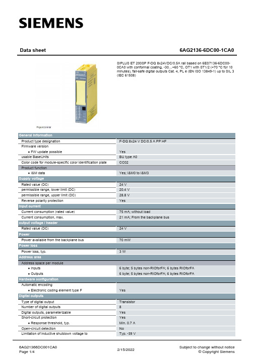
SIPLUS ET 200SP F-DQ 8x24VDC/0.5A rail based on 6ES7136-6DC000CA0 with conformal coating, -30…+60 °C, OT1 with ST1/2 (+70 °C für 10 minutes), fail-safe digital outputs Cat. 4, PL e (EN ISO 13849-1) up to SIL 3 (IEC 61508)
F-DQ 8x24 V DC/0.5 A PP HF
Yes BU type A0 CC02
Yes; I&M0 to I&M3
24 V 20.4 V 28.8 V Yes
75 mA; without load 21 mA; From the backplae; 5 bytes non-RIOforFA; 6 bytes RIOforFA 6 byte; 5 bytes non-RIOforFA; 6 bytes RIOforFA
0.5 A; note derating data in the manual 3 A; note derating data in the manual
3 A; note derating data in the manual 2.5 A; note derating data in the manual 2 A; note derating data in the manual 2 A; note derating information in the manual; only with configured slots to the left and right of the module
3590S-2-102L - 数据表说明书

o nl i ne*RoHS Directive 2002/95/EC Jan. 27, 2003 including annexand RoHS Recast 2011/65/EU June 8, 2011. Specifi cations are subject to change without notice.Customers should verify actual device performance in their specifi c applications.Stop Strength..............................................................................................................................................................................45 N-cm (64 oz.-in.) minimum Mechanical Angle ...........................................................................................................................................................................................3600 ° +10 °, -0 °Torque (Starting & Running) ................................................................................................................................0.35 N-cm (0.5 oz.-in.) maximum (unsealed) 1.1 N-cm (1.5 oz.-in.) maximum (sealed) Mounting ..............................................................................................................................................................................55-80 N-cm (5-7 lb.-in.) (plastic) 90-113 N-cm (8-10 in.-lb.) (metal)Shaft Runout......................................................................................................................................................................................0.13 mm (0.005 in.) teral Runout ...................................................................................................................................................................................0.20 mm (0.008 in.) T.I.R.Shaft End Play ...................................................................................................................................................................................0.25 mm (0.010 in.) T.I.R.Shaft Radial Play ...............................................................................................................................................................................0.13 mm (0.005 in.) T.I.R.Pilot Diameter Runout .......................................................................................................................................................................0.08 mm (0.003 in.) T.I.R.Backlash ............................................................................................................................................................................................................1.0 ° maximum Weight ........................................................................................................................................................................................................Approximately 19 G Terminals ................................................................................................................................................................................................Solder lugs or PC pins Soldering ConditionManual Soldering...........................................................96.5Sn/3.0Ag/0.5Cu solid wire or no-clean rosin cored wire; 370 °C (700 °F) max. for 3 seconds Wave Soldering ...................................................................................96.5Sn/3.0Ag/0.5Cu solder with no-clean fl ux; 260 °C (500 °F) max. for 5 seconds Wash processes .......................................................................................................................................................................................Not recommended Marking .....................................Manufacturer’s name and part number, resistance value and tolerance, linearity tolerance, wiring diagram, and date code.Ganging (Multiple Section Potentiometers) ......................................................................................................................................................1 cup maximum Hardware ............................................................................................................One lockwasher and one mounting nut is shipped with each potentiometer.NOTE: For Anti-rotation pin add 91 after confi guration dash number. Example: -2 becomes -291 to add AR pin.1At room ambient: +25 °C nominal and 50 % relative humidity nominal, except as noted. 2Consult manufacturer for complete specifi cation details for resistances below 1k ohms.BOLDFACE LISTINGS ARE IN STOCK AND READILY AVAILABLETHROUGH DISTRIBUTION. FOR OTHER OPTIONS CONSULT FACTORY.ROHS IDENTIFIER: L = COMPLIANTBLANK = NON-COMPLIANT**** NON-COMPLIANT VERSIONS ARE AVAILABLE BUT NOT RECOMMENDED FOR NEW DESIGNS.Recommended Part Numbers(Printed Circuit)(Solder Lug)(Solder Lug)Resistance (Ω)Resolution (%)3590P-2-102L 3590S-2-102L 3590S-1-102L 1,000.0293590P-2-202L 3590S-2-202L 3590S-1-202L 2,000.0233590P-2-502L 3590S-2-502L 3590S-1-502L 5,000.0253590P-2-103L 3590S-2-103L 3590S-1-103L 10,000.0203590P-2-203L 3590S-2-203L 3590S-1-203L 20,000.0193590P-2-503L 3590S-2-503L 3590S-1-503L 50,000.0133590P-2-104L3590S-2-104L3590S-1-104L100,000.009*R o H S C O M P L I A N T V E R S I O N S A V A I L A B L EonnecPanel Thickness Dimensions(For Bushing Mount Only)1.60 +.08/-.03(.063 +.003/-.001)DIA.ANTI-ROTATION PINAnti-rotation pin hole is shown at six o'clock position for reference only. The actual location is determined by the customer's application. Refer to the front view of the potentiometer to see the location of the optional A/R pin.Panel thickness and hole diameters arerecommended for best fit. However, customers may adjust the dimensions to suit their specific application.Product DimensionsSpecifi cations are subject to change without notice.Customers should verify actual device performance in their specifi c applications.REV. 11/11MOUNTING SURFACE-2, -4, -6, -8 Confi gurations-1, -3, -5, -7 Confi gurationsRecommended PCB LayoutHOLE DIAMETER5.08(.200) 5.08(.200)6.99(.275)SchematicTOLERANCES: EXCEPT WHERE NOTED .508 .127DECIMALS: .XX ± (.02), .XXX ±(.005)FRACTIONS: ±1/64 MM DIMENSIONS:(IN.)Shaft & Bushing Confi gurations(Bushing - DxL, Shaft - D):(-1) Plastic Bushing (3/8 ” x 5/16 ”) and Shaft (.2480 + .001, - .002)(-2) Metal Bushing (3/8 ” x 5/16 ”) and Shaft (.2497 + .0000, - .0009)(-3) Sealed, Plastic Bushing (3/8 ” x 5/16 ”) and Shaft (.2480 + .001, - .002)(-4) Sealed, Metal Bushing (3/8 ” x 5/16 ”) and Shaft (.2497 + .0000, - .0009)(-5) Metric, Plastic Bushing (9 mm x 7.94 mm) and Shaft (6 mm + 0, - .076 mm)(-6) Metric, Metal Bushing (9 mm x 7.94 mm) and Shaft (6 mm + 0, - .023 mm)(-7) Metric, Sealed, Plastic Bushing (9 mm x 7.94 mm) and Shaft (6 mm + 0, - .076 mm)(-8) Metric, Sealed, Metal Bushing (9 mm x 7.94 mm) and Shaft (6 mm + 0, - .023 mm)Terminal Styles“P” Terminal Style“S” Terminal Style。
河北南阳0AP.138.0163-YE3产品样本汇总

YE3系列高效率三相异步电动机(机座号80~400)产品样本代号:0AP.138.0163南阳防爆集团股份有限公司2013年10月 29 日目录1.产品概述 (2)2.执行标准 (2)3.型号说明 (3)4.结构说明 (3)5.使用条件 (4)6.技术数据 (4)7.结构及安装和外形尺寸 (6)8.订货指南 (8)1.产品概述YE3系列高效率三相异步电动机,是我公司自行研制开发的全封闭、自扇冷、鼠笼式、高效率三相异步电动机的基本系列。
效率符合GB18613-2012《中小型三相异步电动机能效限定值及能效等级》中的2级能效。
本系列电动机的功率等级、安装尺寸符合国际电工委员会(IEC)标准的规定,其对应关系与德国DIN42673标准基本相同,可以与Y系列电动机和Y2系列电动机互换。
本系列电动机具有效率高、体积小、噪声低、振动小、温升裕度大、运行可靠、寿命长等优点,而且中心高160及以上电动机端盖上设有不停机注排油装置,并留有安装定子绕组测温和防潮加热带的空间,有利于出口机械设备的配套安装和引进设备的备品备件。
本系列电动机功率范围:0.55kW~560kW ,机座号:80~400。
在YE3基本系列电动机基础上,也可制成YE3-W户外型、YE3-TH湿热带型、YE3-THW 户外湿热带型、YE3-TA干热带型、YE3-TAW户外干热带型、YE3-T热带型、YE3-TW户外热带型及YE3-WF1户外中等防腐蚀型等气候环境条件。
2.执行标准GB/T 191 包装储运图示标志GB 755 旋转电机定额和性能GB/T 997 旋转电机结构型式、安装型式及接线盒位置的分类(IM代码)GB/T 1032 三相异步电动机试验方法GB/T 1993 旋转电机冷却方法GB 1971 旋转电机线端标志与旋转方向GB/T 2423.1 电工电子产品环境试验第2标准:试验方法试验A:低温GB/T 2423.4 电工电子产品环境试验第2部分: 试验方法试验Db:交变湿热(12h+12h循环)GB/T 2423.16 电工电子产品环境试验第2标准:试验方法试验J和导则长霉GB/T 2423.17 电工电子产品基本环境试验规程试验Ka: 盐雾试验方法GB/T 2423.33 电工电子产品环境试验第2标准:试验方法试验Kca:高浓度二氧化硫试验GB/T 4772.1 旋转电机尺寸和输出功率等级第1部分:机座号36~400和凸缘号55~1080GB/T 4942.1 旋转电机整体结构的防护等级(IP代码)分级GB 10068 轴中心高为56mm及以上电机的机械振动振动的测量、评定及限值GB/T 10069.1 旋转电机噪声测定方法及限值第1部分:旋转电机噪声测定方法GB 14711 中小型旋转电动机安全要求GB 18613 中小型三相异步电动机能效限定值及能效等级GB/T 12351 热带型旋转电机环境技术要求GB/T 22719.1 交流低压电机散嵌绕组匝间绝缘第1部分:试验方法JB/T 4159 热带电工产品通用技术要求3.型号说明电动机型号代表意义示例:Y E 3 - 355 M 1 - 4 W异步电动机特殊环境代号(户外型)极数( 4极)高效率1号铁心长设计序号机座长度(M表示中机座)机座的中心高(355mm)4.结构说明4.1电动机主体外壳防护等级为:IP55。
AHT21 产品手册说明书

AHT21 产品手册温湿度传感器• 完全标定应用范围暖通空调 、除湿器、测试及检测设备、消费品、汽车 、自动控制、数据记录器、气象站、家电、湿度调节、医疗及其他相关温湿度检测控制。
图 1: AHT21 传感器封装图(单位:mm 公差:±0.1mm )2• 数字输出,I C 接口• 优异的长期稳定性• 采用SMD封装适于回流焊• 响应迅速、抗干扰能力强Top viewFront viewButtom view0.40.553.03.01.02.0Top viewButtom view1.00.50.50.95传感器性能相对湿度温度图 3温度典型误差和最大误差。
±0±2±4±6±8±10图 2 25°C 时相对湿度的最大误差。
△R H (%RH )相对湿度(%RH )电气特性表2 电气特性。
包装信息此精度为出厂检验时,传感器在 25℃供电电压为3.3V 条件下的测试精度。
此数值不包括迟滞和非线性,并只适用于非冷凝条件。
25℃和1m/s 气流条件下,达到一阶响应 63%所需时间。
正常工作范围:0-80%RH, 超出此范围,传感器读数会有偏差(在90%RH 湿度下 200 小时后,漂移<3%RH)。
如果传感器周围有挥发性溶剂、带刺激性气味的胶带、粘合剂以及包装材料,读数可能会偏高。
详细说明请参阅相关文件。
供电电流和功耗的最小值和最大值都是基于 VDD = 3.3V 和 T<60℃的条件。
平均值为每两秒中进行一次测量的数值。
响应时间取决于传感器基片的导热率。
表 1 湿度特性表表 3 温度特性表表4 包装信息。
123456温度(℃)表1中给出的功耗与温度和供电电压VDD有关。
关于功耗的估测参见图6和7。
请注意图6和7中的曲线为典型自然特性,有可能存在偏差。
图6VDD=3.3V时,典型的供电电流与温度的关系曲线(休眠模式)。
PMAC801A智能型电动机保护控制器

第 4 章 控制器功能配置
4.1 功能配置
PMAC801A 具备启动超时保护、启动过流保护、过载保护、tE 时间保护、过流堵
转保护、断相保护、电流不平衡保护、短路保护、接地保护、欠载保护、外部故障保护,
漏电保护、温度保护、过压保护、欠压保护、欠功率保护、相序保护、模拟量输入保护
第 1 页 共 28 页
第 1 章 产品介绍
1.1 设计说明
PMAC801A 智能型电动机保护控制器是集电动机的测量、保护和控制功能于一体 新一代增强型的高性能电动机保护装置。适用于额定电压为 AC380V 或 AC690V 的普 通三相交流异步电动机。取代了电动机控制中心(MCC)中常用的分散装置,大大简化 电动机控制回路结构,提高电动机控制的可靠性及先进性,同时也降低了综合应用成本。
PMAC801A 采用主体和 CT 模块分体设计,最小完整系统由主体,显示和专用 CT 模块构成,主体与显示尺寸固定,专用 CT 模块尺寸分为 2A、6.3A、25A、100A、250A、 400A、820A。
第 3 页 共 28 页
第 2 章 技术参数
2.1 系统参数
电动机额定电压:交流 380V 或 690V 电动机额定电流:0.5~820A 控制器电源电压:交流 85V~265V,直流 100V~300V 通用。 开关量输入:外部交流 220V,外部直流 220V,内部直流 24V 供电。 控制继电器:250VAC/10A,380VAC/5A,110VDC/0.25A。 信号继电器:250VAC/5A。
第 22 页 共 28 页
第 5 章 电动机控制及其他功能
5.1 电动机运行状态的划分
PMAC801A 将电动机运行分为四种状态:就绪状态、启动状态、运行状态、停车 状态。
MM3513A01NRH_规格书_100914
1.功能 FUNCTION
2.封装 PACKAGE
3.包装方式 PACKING
3.1 包装规格 PACKING SPECIFICATIONS
・ 锂电池平衡控制用电压监视IC Voltage Monitor for Li-ion cell balance
・ SOT-25A
卷带 ・ テーピング
(Taping)
℃
9. 电气特性 Electrical characteristics
项目 Parameter 动作输入电压 Operating input voltage
记号 Symbol VDD1
条件 Conditions VDD-VSS
最小 Min.
1.5
标准 Typ.
-
Topr=25℃
最大 Max.
单位 Unit
0.005 0.010 0.015 V C
T=25℃ VDD=3.4V→4.6V
0.20 0.25 0.30 s C
检测延时时间 Detection delay time
tVdet
T=-5~60℃
*4
VDD=3.4V→4.6V
0.18
0.25 0.33
s
C
T=-30~70℃ *4 VDD=3.4V→4.6V
检测电压 Detection voltage
*3
Vdet
T=-5~60℃ R1=330Ω
*4 4.125 4.150 4.175 V C
T=-30~70℃ R1=330Ω
*4 4.105 4.150 4.195 V
C
滞后电压 Hysteresis voltage
*3
Vhys
T=-30~70℃ R1=330Ω
安柏精密仪器有限公司AT527系列电池测试仪用户手册说明书
用户手册User’s GuideRev.A9固件说明:适用于主程序Rev.C1.02及以上的版本AT527系列电池测试仪安柏精密仪器有限公司电话:0512-********©2005-2018 Applent InstrumentsLtd..产品咨询联系电话:0512-63976842 AT527系列用户手册安全须知当你发现有以下不正常情形发生,请立即终止操作并断开电源线。
立刻与安柏科技销售部联系维修。
否则将会引起火灾或对操作者有潜在的触电危险。
●仪器操作异常。
●操作中仪器产生反常噪音、异味、烟或闪光。
●操作过程中,仪器产生高温或电击。
●电源线、电源开关或电源插座损坏。
●杂质或液体流入仪器。
安全信息为避免可能的电击和人身安全,请遵循以下指南进行操作。
免责声明用户在开始使用仪器前请仔细阅读以下安全信息,对于用户由于未遵守下列条款而造成的人身安全和财产损失,安柏科技将不承担任何责任。
仪器接地为防止电击危险,请连接好电源地线。
不可在爆炸性气体环境使用仪器不可在易燃易爆气体、蒸汽或多灰尘的环境下使用仪器。
在此类环境使用任何电子设备,都是对人身安全的冒险。
不可打开仪器外壳非专业维护人员不可打开仪器外壳,以试图维修仪器。
仪器在关机后一段时间内仍存在未释放干净的电荷,这可能对人身造成电击危险。
不要使用已经损坏的仪器如果仪器已经损害,其危险将不可预知。
请断开电源线,不可再使用,也不要试图自行维修。
不要使用工作异常的仪器如果仪器工作不正常,其危险不可预知,请断开电源线,不可再使用,也不要试图自行维修。
不要超出本说明书指定的方式使用仪器超出范围,仪器所提供的保护措施将失效。
产品咨询联系电话:0512-63976843安装和设置向导有限担保和责任范围常州安柏精密仪器有限公司(以下简称Applent )保证您购买的每一台AT527在质量和计量上都是完全合格的。
此项保证不包括保险丝以及因疏忽、误用、污染、意外或非正常状况使用造成的损坏。
Cessna产品型号说明书
CESSNA150 A thru M O-200 CH48108-1 CFO-100-1F150 F thru M O-200 CH48108-1 CFO-100-1A150L O-200 CH48108-1 CFO-100-1FA150 O-200 CH48108-1 CFO-100-1152 O-235-L2C, H2C CH48110-1 –162 0-200-D CH48108-1 –C-172172 A thru H O-300 CH48108-1 CFO-100-1172 I thru M O-320 CH48110-1 CFO-100-1172N O-320-H2AD CH48103-1 –172P O-320-D2J CH48111-1 CFO-101-1F172 D thru H O-300 CH48108-1 CFO-100-1FR172 E thru K IO-360 CH48108-1 CFO-100-1R172K IO-360-K CH48108-1 –172R and S IO-360-L2A CH48110-1 –172RG O-360-F1A6 CH48110-1 CFO-100-1172S IO-360-L2A CH48110-1 –177 O-320 CH48110-1 CFO-100-1177A, B O-360-A1F6D CH48103-1 CFO-100-1177RG IO-360-A1B6D CH48103-1 CFO-100-1180 A thru J O-470 CH48108-1 CFO-100-1180Q O-470-U++ CH48108-1 CFO-100-1180-S/N 53087 & Up 1111O-470-U++ CH48108-1 –C-182182 A Thru P O-470 CH48108-1 CFO-100-1182Q, R O-470-U++ CH48108-1 CFO-100-1182S IO-540-AB1A5 CH48110-1 –A182 K thru N O-470 CH48108-1 CFO-100-1182-S/N 67042 & Up O-470-U++ CH48108-1 –F182-S/N 00130 & Up O-470-U++ CH48108-1 –R182 O-540-J3C5D CH48103-1 CFO-100-1T182 O-540-L3C5D CH48103-1 CFO-100-1TR182, FTR182 O-540-L3C5D CH48103-1 CFO-100-1185 A thru D IO-470, IO-520 CH48108-1 CFO-100-1A185E, F IO-470, IO-520 CH48108-1 CFO-100-1185-S/N 03852 & Up IO-520 CH48108-1 –188 O-470, IO-520 CH48108-1 CFO-100-1188-S/N 03474 & Up IO-520D CH48109-1 –T188-S/N 03474 & Up TSIO-520 CH48109-1 –205A IO-470 CH48108-1 CFO-100-1C-206 IO-540 CH48110-1 CFO-100-1206 A thru G IO-520 CH48108-1 CFO-100-1206H IO-540-AC1A5 CH48110-1 –206-S/N 05030 & Up IO-520 CH48109-1 –206-S/N 05030 & Up TSIO-520 CH48109-1 –U206 IO-520 CH48108-1 CFO-100-1T-206H TI0540-AJ1A CH48110-1 –TU-206 TSIO-520 CH48108-1 CFO-100-1P206 IO-520 CH48108-1 CFO-100-1TP206 TSIO-520 CH48108-1 CFO-100-1207 IO-520 CH48108-1 CFO-100-1207-S/N 05227 & Up IO-520 CH48109-1 –T207-S/N 05227 & Up TSIO-520 CH48109-1 –T207 TSIO-520 CH48108-1 CFO-100-1210 IO-470, IO-520 CH48108-1 CFO-100-1210-S/N 63373-63375 & Up IO-520 CH48109-1 –T210-S/N 63373-63375 & Up TSIO-520 CH48108-1 –P210-S/N 278 &Up TSIO-520 CH48108-1 –T210, P210-S/N 1-277 TSIO-520++ CH48108-1 CFO-100-1 32Aircraft engines not listed, but equipped with oil fi lters at overhaul, may accept Champion fi lters. Write Aviation Service Deptment for further information. Please include description of your engine. ++ Reference page 25-26 for other TCM application data. * Requires Lyco (54E23093) AEROSPATIABLE (SocataTB9 Tampico O-320-D2A CH48110-1 CFO-100-1TB10 Tobago O-360-A1AD CH48110-1 CFO-100-1TB20 Trinidad IO-540-C4D5D CH48103-1 CFO-100-1TB21 Trinidad TC TIO-540-AB1AD CH48103-1 CFO-100-1TB30 AEIO-540-L1B5D CH48103-1 CFO-100-1AEROSTAR (See Piper)BEECHBONANZAE33A, F33A, F33B, F33C IO-520 – CFO-100-1E33A, F33A, F33B, F33C IO-520B CH48109-1 –G-33 IO-470N CH48108-1H-35 O-470 CH48108-1 –J, K, M-35 IO 470-C CH48108-1N, P-35 IO-470-N CH48108-1S35, V35, V35A, V35B IO-520 – CFO-100-1S35 IO-520B CH48109-1 –V35TC, V35A-TC, V35B-TC TSIO-520 – CFO-100-1V35TC, V35A-TC, -V35B-TC TSIO-520D CH48109-1 –V35, V35A, V35B IO-520B CH48109-1 –36, A36 IO-520B CH48109-1 –A36TC, B36TC TSIO-520-UB CH48109-1 –B36-550 IO-550 CH48109-1 –DEBONAIR/BONANZAC33A, E33A, E33C IO-520 – CFO-100-1C33A, E33A, F33C IO-520B CH48109-1 –MUSKETEERSport III O-320 CH48110-1 CFO-100-123 O-320 CH48110-1 CFO-100-1A23-19, 19A, B19 Sport O-320 CH48110-1 CFO-100-1A23, 23, A23A IO-346 – CFO-100-1A23, A23A IO-346A CH48109-1 –B23, C23 Sundowner O-360 CH48110-1 CFO-100-1B23 O-360A4JD CH48103-1 CFO-100-1SIERRA24, A-24, A-24R, B-24R, C-24R IO-360, -L2A CH48110-1 CFO-100-1SKIPPER77 O-235-L2C CH48110-1 –BEECHBARONC55, D55, E55, 58 IO-520 – CFO-100-1C55, D55, E55, 58 IO-520C CH48109-1 –56TC, A56TC TIO-541-E CH48104-1 CFO-101-1Baron 58P TSIO-520-L++ – CFO-100-1Baron 58P, 58TC TSIO-520-L, -W, -B CH48108-1 –Baron 58C, 550 IO-550 CH48109-1 –DUKE60, A60, B60 TIO-541 CH48104-1 CFO-101-1QUEEN AIR65, 70 IGSO-480 CH48111-1 CFO-101-180, 88, B80 IGSO-540 CH48111-1 CFO-101-1TRAVEL AIR95, B95 O-360 CH48110-1 CFO-100-1B95A, D95A, E95 IO-360, L2A CH48110-1 CFO-100-1DUCHESS LO-360-A1G6D &76 O-360-A1G6D CH48103-1BELLANCA17-31A, 17-31ATC IO-540-K CH48110-1 CFO-100-117-31A Viking IO-540-K CH48110-1 CFO-100-117-31A Viking IO-520-D – CFO-100-117-31ATC Turbo TIO-540 CH48110-1 CFO-100-1ChampionEngine Spin-On ChampionModel Model Filter ElementChampionEngine Spin-On ChampionModel Model Filter ElementNOTE: A ll Cessna aircraft modifi ed under Cessna Service BulletinSEB-93-1 or MEB 93-1, require Champion Oil Filter CH48108-1.The CH48109-1 may also be used if clearance permits installation.Aircraft Engine ApplicationsCESSNA T303 LTSIO-520-AE &TSIO-520-AE CH48109-1 –310 C thru Q IO-470 CH48108-1 CFO-100-1310 RIO-520-M CH48108-1 –T310P, Q, R TSIO-520-B CH48108-1 CFO-100-1320-A TSIO-470 CH48104-1 –320-B, C TSIO-470 CH48109-1 CFO-101-1320-D TSIO-520 – CFO-100-1320-D, E, F TSIO-520-B CH48108-1 –335 TSIO-520-EB CH48109-1 –336 IO-360 CH48108-1 CFO-100-1337 IO-360 CH48108-1 CFO-100-1P337, P337H TSIO-360 CH48108-1 CFO-100-1T337H TSIO-360-H CH48108-1 CFO-100-1340 TSIO-520-K CH48108-1 –340A TSIO-520-N, -NB CH48109-1 CFO-100-1401/402TSIO-520-E CH48108-1 CFO-100-1402C TSIO-520-VB CH48109-1 CFO-100-1404GTSIO-520-M CH48111-1 CFO-101-1411-S/N 000 thru 0126 GTSIO-520-C CH48104-1 –411-S/N 0127 and up GTSIO-520-C CH48111-1 CFO-101-1414, 414A TSIO-520-J, -N CH48108-1 –421A, BGTSIO-520-D, -H, CH48111-1 CFO-101-1421C-S/N 1017 thru 1404 -L, -N, ++ CH48111-1 CFO-101-1CIRRUS AIRCRAFT SRV, SR20I0-360ES CH48108-1SR22I0-550N CH48109-1COLUMBIA/LANCAIR COLUMBIA 300, 350 I0-550N CH48109-1 CFO-100-1COLUMBIA 400 TS10-550 CH48109-1 CFO-100-1DIAMOND AIRCRAFT DA20-1C I0-240 CH48108-1 CFO-100-1DA40-180I0-360 CH48110-1 CFO-100-1GULFSTREAM AMERICAN (Single Engine Models)AA-1, 1A, 1B, 1B Trainer, TR 2/Lyco O-235 CH48110-1 CFO-100-1A1C Lynx, T-Cat Lyco O-235-L CH48110-1 CFO-100-1AA-5 Traveler Lyco O-320-E CH48110-1 CFO-100-1AA-5A Cheetah Lyco O-320-E CH48110-1 CFO-100-1AA-5B Tiger Lyco O-360-A4K CH48110-1 CFO-100-1Cougar 2/Lyco O-320-D CH48110-1 CFO-100-1COMMANDER 112, 112A IO-360-C, -L2A CH48110-1 CFO-100-1112TC TO-360-C1A6D CH48103-1 CFO-100-1114IO-540-T4A5D CH48103-1 CFO-100-1500B, 500U IO-540 CH48110-1 CFO-100-1700TIO-540-R2AD CH48103-1 CFO-100-1 33Aircraft engines not listed, but equipped with oil fi lters at overhaul, may accept Champion fi lters. Write Aviation Service Deptment for further information. Please include description of your engine. ++ Reference page 25-26 for other TCM application data. * Requires Lyco (54E23093)MAULEM5-180C, MX7-180 O-360-C, -C1F CH48110-1 M5-210C IO-360D, -L2A M5-210TCTO-360-C1A6D CH48103-1 M5-235C, M6-235, M7-235 O-540-J1A5D CH48103-1 MX-7-235O-540-W1A5D CH48103-1MOONEY AIRCRAFTM20A, B, Mark21O-360 CH48110-1M20D MasterO-360 CH48110-1 CFO-100-1 M20C RangerO-360 CH48110-1M20G StatesmanO-360CH48110-1 CFO-100-1 M20E ChaparralIO-360, -L2A CH48110-1 CFO-100-1 M20F Executive IO-360, -L2ACH48110-1 CFO-100-1 M20J-201 IO-360-A3B6D, -L2A CH48103-1 – M20K-231 TSIO-360-G, LB CH48108-1 M20M-TLS TIO-540-AFIA, B CH48110-1M20RIO-550 CH48108-1 –M22 Mustang TIO-541CH48110-1 CFO-100-1 M20K-252 TSE TSIO-360-MB1CH48108-1 –PIPER CUBPA-18 “150” O-320 CH48110-1 CFO-100-1 TRI-PACERPA-22 “150”O-320 CH48110-1 CFO-100-1 PA-22 “160”O-320CH48110-1 CFO-100-1 COMANCHEPA-24 “180” O-360CH48110-1 CFO-100-1 PA-24 “250”O-540 or IO-540 CH48110-1 CFO-100-1 PA-24B, PA-24C “260”O-540 or IO-540 CH48110-1 CFO-100-1 PA-24 Turbo “260”IO-540 CH48110-1 CFO-100-1 PAWNEEPA-25 “150” O-320 CH48110-1 CFO-100-1 A25 “260”O-540 CH48110-1 CFO-100-1 PA-36 Brave6-285B CH48109-1 –PA-36-375 Brave IO-720-D1C CH48110-1 CFO-100-1 PA-36-400 BraveIO-720D1CD CH48104-1 CFO-101-1 CHEROKEE, CADET PA-28 “140”O-320 CH48110-1 CFO-100-1 PA-28 “150”O-320 CH48110-1 CFO-100-1 PA-28 “160”, “161” O-320 CH48110-1 CFO-100-1 PA-28 “180”O-360CH48110-1 CFO-100-1 PA-28 “180”, “181”O-360-A4M CH48110-1 CFO-100-1 PA-28 “235”O-540 CH48110-1 CFO-100-1 PA-28 “151”O-320CH48110-1 CFO-100-1 ARROWPA-28R “180”IO-360, L2ACH48110-1 CFO-100-1 PA-28R “180 IO-360-C1CD, L2A CH48103-1 CFO-100-1 PA-28R “200” Arrow II IO-360, L2A CH48110-1 CFO-100-1 PA-284 “200” Turbo Arrow IIITSIO-360 CH48108-1 – PA-28-R-201TTSIO-360-F1CH48108-1Champion Engine Spin-On Champion Model ModelFilter ElementChampionEngine Spin-On Champion Model ModelFilter Element Aircraft Engine Applications34TWIN COMMANCHEPA-30 “160” Turbo IO-320 CH48110-1 CFO-100-1PA-39 “160” IO-320 CH48110-1CFO-100-1LIO-320 CH48110-1 CFO-100-1PA-39 “160” Turbo IO-320 CH48110-1 CFO-100-1LIO-320 CH48110-1 CFO-100-1NAVAJOPA-31 “300” IO-540 CH48110-1 CFO-100-1PA-31 “310” Turbo TIO-540 CH48110-1 CFO-100-1PA-31 “325” IO-540-F2BD CH48103-1 CFO-100-1LTIO-540-F2BD CH48103-1 CFO-100-1PA-31 “350” Chieftain TIO-540-J2BD CH48103-1 CFO-100-1LTIO-540-J2BD CH48103-1 CFO-100-1PA-31P “425” TIGO-541 CH48104-1 CFO-101-1PA-31P “350” Mojave TIO/LIO-540-V2AD CH48104-1SENECAPA-34 IO-360C CH48110-1 CFO-100-1LIO-360C CH48110-1 CFO-100-1PA-34 IO-360-C1E6D CH48103-1 CFO-100-1LIO-360-C1E6D CH48103-1 CFO-100-1Seneca II LTSIO-360-E CH48108-1 –TSIO-360-E CH48108-1 –Seneca III TSIO-360-KB CH48108-1PA-34-220T LTSIO-360-KB CH48108-1PIPER AEROSTARPA-60-600, -600A IO-540-G, -K CH48110-1 CFO-100-1PA-60-604, -601B IO-540-P, -S CH48110-1 CFO-100-1PA-60-601P IO-540-S CH48110-1 CFO-100-1PA-60-602P IO-540-AA1A5 CH48110-1 CFO-100-1SEMINOLEPA-44-180 O-360-E1AD CH48103-1* CFO-100-1PA-44-180T TO-360-E1A6DLTO-360-E1A6D CH48103-1* CFO-100-1 ChampionEngine Spin-On ChampionModel Model Filter ElementChampionEngine Spin-On Champion Model Model Filter ElementDAKOTAPA-28-235 O-540-J3A5D CH48103-1* CFO-100-1PA-28-201T TSIO-360-FB CH48108-1 –CHEROKEE SIXPA-32 “260” O-540 CH48110-1 CFO-100-1PA-32 “300” IO-540 CH48110-1 CFO-100-1PA-32R “300” IO-540-K1AD CH48103-1* CFO-100-1PA-32R “300” TIO-540-S1AD CH48103-1* CFO-100-1PA-32RT-300T TIO-540-S1AD CH48103-1* CFO-100-1PA-32-301 IO-540-K1G5D CH48103-1* CFO-100-1PA-32-301 TIO-540-S1AD CH48103-1* CFO-100-1PA-32R-301 IO-540-K1G5D CH48103-1* CFO-100-1PA-32R-301 TIO-540-S1AD CH48103-1* CFO-100-1TOMAHAWKTrainer PA-38-112 O-235-L2C CH48103-1* CFO-100-1MALIBUPA-46-301P Cont TSIO-520-BE CH48109-1MALIBU MIRAGEPA-46-350-P Lyco TIO-540-AE2A CH48103-1APACHEPA-23 “150” O-320 CH48110-1 CFO-100-1PA-23 “160” O-320 CH48110-1 CFO-100-1PA-23 “235” O-540 CH48110-1 CFO-100-1AZTECPA-23 “250” O-540 CH48110-1 CFO-100-1“C” PA-23 IO-540 CH48110-1 CFO-100-1PA-23 Turbo “250” IO-540 CH48110-1 CFO-100-1“C”, “D”, “E”, “F”PA-23 Turbo “250” TIO-540 CH48110-1 CFO-100-1Dimensional DataChampion Thread Dry WeightPart No. A B C D (SAE) Lbs./Kg.CH48103-1 4.48” (11.4 cm) 0.43” (1.09 cm) 1.00” Hex (2.54 cm) 3.71” (9.4 cm) 13/16-16-UNS-2B 1.32lbs. (0.59kg) CH48104-1 5.73” (14.6 cm) 0.43” (1.09 cm) 1.00” Hex (2.54 cm) 3.71” (9.4 cm) 13/16-16-UNS-2B 1.41lbs. (0.64kg) CH48108-1 4.48” (11.4 cm) 0.43” (1.09 cm) 1.00” Hex (2.54 cm) 3.71” (9.4 cm) 3/4-16-UNF-2B 1.40lbs. (0.64kg) CH48109-1 5.73” (14.6 cm) 0.43” (1.09 cm) 1.00” Hex (2.54 cm) 3.71” (9.4 cm) 3/4-16-UNF-2B 1.51lbs. (0.68kg) CH48110-1 4.48” (11.4 cm) 0.43” (1.09 cm) 1.00” Hex (2.54 cm) 3.71” (9.4 cm) 3/4-16-UNF-2A 1.38lbs. (0.63kg) CH48111-1 5.73” (14.6 cm) 0.43” (1.09 cm) 1.00” Hex (2.54 cm) 3.71” (9.4 cm) 3/4-16-UNF-2A 1.47lbs. (0.67kg)Popular spin-on oil fi ltersAircraft engines not listed, but equipped with oil fi lters at overhaul, may accept Champion fi lters. Write Aviation Service Department for furtherinformation. Please include description of your engine. * Requires Lyco (54E23093)Aircraft Engine Applications。
SA808 产品说明书
SA808 INSTRUCTION MANUAL We’ll Make It Stress-FreeIf you have any questions along the way, just give us a call.1-800-359-5520. We’re ready to help!Scan for easy install video/4472Before getting started, let’s make sure this product is perfect for you!WARNING:This product contains small items that could be a choking hazard if swallowed.Before starting assembly, verify all parts are included and undamaged. If any parts are missing or damaged, do not return the damaged itemto your dealer; contact Customer Service. Never use damaged parts!353. Use a drywall saw or similar tool to cut the drywall where marked. Remove cut section of drywall.1. Break out the sections of the housing 02 that are required to install the power and cable outlets that are needed.2. Thread the elastic-velcro strap into the housing 02.681.To use the ECO-Mini (purchased separately) in the SA808, first remove feet.2. Fit the ECO-Mini into the ECO-Mini bracket 05 supplied with the SA808.3. Use two of the screws from the feet to secure the ECO-Mini in the bracket 05.4. Slide the ECO-Mini and bracket 05 into the top of the housing 02. Lock the bracket 05 into the housing 02 by sliding it towards thecorner until you feel it catch.5. Use the elastic-velcro strap 03 to attach components to the housing 02.6. Power the ECO-Mini with the power cord supplied with the ECO-Mini.The SA808 can be installed behind most large wall plates of wall mounts or underneath or above most small wall plates. To access the SA808 after installation, disconnect all cables and wires from the TV, then either slide or remove the arm or TV mount from the wall plate. IMPORTANT: Check your TV owner’s manual to see if there are any special requirements for mounting or removing your TV.12 5.83 in.[148.0 mm]7.80 in.[198.1 mm]13.80 in.[350.5 mm]11.80 in.[299.8 mm]4.00 in.[101.6 mm] 125°13Before getting started, let’s make sure this product is perfect for you!- see page 21. Will your accessories weigh more than 50 lb (22.7 kg)?No — Perfect!Yes — This product is NOT compatible. Visit or call 1-800-359-5520 [UK: 0800 056 2853] to fi nd a compatible product.2. What is your wall made of?3. Do you have all of the tools needed?4. Ready to begin?Please read through these instructions completely to be sure you’re comfortable with this easy install process.If you do not understand these instructions or have doubts about the safety of the installation, assembly or use of this product, contact Customer Service at 1-800-359-5520 [UK: 0800 056 2853].CAUTION: Avoid potential personal injuries and property damage!●Do not use this product for any purpose not explicitly specifi ed by manufacturer.●Manufacturer is not responsible for damage or injury caused by incorrect assembly or use.Supplied Parts- see page 3WARNING:This product contains small items that could be a choking hazard if swallowed.Before starting assembly, verify all parts are included and undamaged. If any parts are missing or damaged, do not return the damaged item to your dealer; contact Customer Service. Never use damaged parts!STEP 1 Cut Hole for Housing- see page 4CAUTION:Avoid potential personal injuries and property damage!●Minimum drywall thickness 1/2 in. (13 mm).●Box must be mounted between studs that are at least 16 in. (406 mm) apart.141. Locate the studs using an edge-to-edge stud finder. Verify the edges of the studs using an awl or thin nail. Mark the inner edges of thestuds with pencil.2. The open area on the left of the template 01 should line up the the inner edge of the left stud. This will allow space for the placement ofa power box on the right side of the housing 02. Level the template 01 and use a pencil to mark the open area of the template 01.3. Use a drywall saw or similar tool to cut the drywall where marked. Remove cut section of drywall.WARNING!Electric Shock Hazard! Avoid potential serious injuries or death. Ensure there are no electrical wires behind the wall before cutting or drilling into the surface.WARNING!Explosion and Fire Hazard! Avoid potential serious injuries or death. Ensure there are no gas lines behind the wall before cutting or drilling into the surface.4. Install wires and cables.2. Thread the elastic-velcro strap into the housing 02.3. Mount a power outlet (if needed) to the housing 02. Slide cables and additional wires through the hole in the bottom of the housing 02and the rubber cable grommet 04. Fit the cable grommet 04 into the hole.4. Using a screwdriver, turn the screws in the corners of the housing 02 . These will raise the locking tabs in the rear of the housing 02 tosecure it to the wall. Tighten only until secure. Do not over-tighten screws.STEP 3 Install Components- see page 8ECO-Mini (purchased separately) with the SA808 - Optional1. To use the ECO-Mini (purchased separately) in the SA808, first remove feet.2. Fit the ECO-Mini into the ECO-Mini bracket 05 supplied with the SA808.153. Use two of the screws from the feet to secure the ECO-Mini in the bracket 05.4. Slide the ECO-Mini and bracket 05 into the top of the housing 02. Lock the bracket 05 into the housing 02 by sliding it towards thecorner until you feel it catch.5. Use the elastic-velcro strap 03 to attach components to the housing 02.6. Power the ECO-Mini with the power cord supplied with the ECO-Mini.Positioning- see page 11The SA808 can be installed behind most large wall plates of wall mounts or underneath or above most small wall plates. To access the SA808 after installation, disconnect all cables and wires from the TV, then either slide or remove the arm or TV mount from the wall plate.IMPORTANT: Check your TV owner’s manual to see if there are any special requirements for mounting or removing your TV. Dimensions- see page 12161718Milestone AV Technologies and its affi liated corporations and subsidiaries (collectively, “Milestone”), intend to make this manual accurate and complete. However, Milestone makes no claim that the information contained herein covers all details, conditions, or variations. Nor does it provide for every possible contingency in connection with the installation or use of this product. The information contained in this document is subject to change without notice or obligation of any kind. Milestone makes no representation of warranty, expressed or implied, regarding the information contained herein. Milestone assumes no responsibility for accuracy, completeness or suffi ciency of the information contained in this document.©2013 Milestone AV Technologies, a Duchossois Group Company. All rights reserved. Sanus is a division of Milestone.All other brand names or marks are used for identifi cation purposes and are trademarks of their respective owners.Thank you for choosing Sanus!Please take a moment to let us know how we did:SANUS• 6436 City West Parkway • Eden Prairie, MN 55344 USACall us: 800-359-5520UK: 0800 056 28536901-002209 00Emailus:**************Find us on the web: 。
- 1、下载文档前请自行甄别文档内容的完整性,平台不提供额外的编辑、内容补充、找答案等附加服务。
- 2、"仅部分预览"的文档,不可在线预览部分如存在完整性等问题,可反馈申请退款(可完整预览的文档不适用该条件!)。
- 3、如文档侵犯您的权益,请联系客服反馈,我们会尽快为您处理(人工客服工作时间:9:00-18:30)。
YW系列(机座号80~355)无火花型
三相异步电动机
产品样本
代号:0AP.138.0102a
南阳防爆集团股份有限公司
2009年06月03日
目录
1.概述 (3)
2.型号说明 (3)
3.结构说明 (3)
4.使用条件 (4)
5.技术数据 (5)
6.结构及安装和外形尺寸 (9)
7.订货指南 (10)
1 概述
YW系列无火花型三相异步电动机(以下简称无火花型电动机)是我公司研制开发的防爆电机系列产品。
该系列电动机具有体积小、重量轻、外形美观、噪音低、效率高、可靠性高、性能优良、安装使用维修方便等特点,该电动机被评为中国名牌产品。
YW系列无火花型三相异步电动机是按GB3836.1-2000《爆炸性气体环境用电气设备第1部分:通用要求》和GB3836.8-2003《爆炸性气体环境用电气设备第8部分:“n”型电气设备》的规定设计制造的。
效率执行GB18613-2006《中小型三相异步电动机能效限定值及节能评价值》中的能效限定值标准,效率达到3级能效等级,等效于IEC60034-30中IE1效率标准。
其防爆标志为ExnAⅡT3,适用于工厂IIA类设备,具有引燃温度为T1、T2、T3组的可燃性气体或蒸气与空气形成的爆炸性混合物场所。
YW系列电动机的功率等级、安装尺寸符合国际电工委员会(IEC)标准的规定,其对应关系与德国DIN42673标准相同,有利于出口机械设备的配套安装和引进设备的备品备件。
YW系列电动机的功率范围为0.55~315Kw,机座中心高80~355mm。
YW系列无火花型电动机主体外壳的防护等级不低于IP54,接线盒外壳防护等级不低于IP55,电动机的冷却方式为IC411,并可按要求制成户外型(W)、户外防中等腐蚀型(WF1)。
2 型号说明
2.1 电动机型号代表意义示例:YW355L1–2 WF1
Y----异步电动机 W----无火花型
355--机座中心高(355mm) L1---长机座,1号铁心长 2----极数(2极) WF1--户外防中等腐蚀
2.2电动机防爆标志代表的意义:ExnAIIT3
Ex---标志(防爆) n----电气设备防爆型式(无火花型) AII----电气设备类别级别 T3---温度组别(T3)
3 结构说明
3.1 定子
定子绕组采用厚漆膜导线,有绕组定子铁心经真空压力浸漆处理,保证导线之间的空隙填充良好,使之成为一个完整的整体,绕组和绝缘具有良好的电气、
机械、热稳定和防潮性能。
如果用户需要还可以增加定子绕组测温装置和安装防
潮加热带,对绕组温度进行监控和保护。
3.2 转子
采用热套工艺将铸铝转子固定在轴上,转子经动平衡校验,电动机运行平稳、振动小。
轴采用45#钢制成,电动机有一个圆柱形轴伸,借联轴器或正齿轮传动。
3.3 轴承和轴承室
轴承采用电机专用低振动、低噪声轴承,H132及以下采用双面密封轴承,
在轴伸端装有波形弹簧垫片,以适度的弹力压靠轴承,有效地抑制电动机运转时
产生的振动和噪声;H160及以上电动机在端盖上安装有注排油装置,轴承外盖
储油腔大,可不停机加注轴承润滑脂。
如果用户需要H200及以上还可增设轴承
温度监控装置,对轴承温度进行监控。
3.4 风扇、风罩
风扇经静平衡校验与轴采用键联接,运行平稳,风扇小,噪声低。
风罩为钢
板结构锥形风罩,在防止一定大小的固体异物进入壳内的前提下,具有最大的通
风面积和最好的通风散热效果,防护等级为IP20。
3.5 在出厂时机座号315及以上电动机的轴伸端安装有轴承锁紧装置,在运输过
程中可有效保护电动机轴承不致受损。
4 使用条件
4.1环境温度:环境空气温度随季节而变化,最高不超过40℃,最低不低于-15℃。
4.2 海拔:不超过1000m。
4.3 额定频率:50Hz。
4.4 额定电压:380V、400V、415V、660V、380/660V、660/1140V。
4.5 工作制:连续工作制(S1)。
4.6户外型(W):适用于户外场所。
4.7户外防腐型(WF1) :适用于户外且具有中等腐蚀性介质场所。
注:用户对频率、电压及使用环境条件等有特殊要求时,请订货时注明。
5 技术数据
5.1 YW系列无火花型电动机机座号与转速及功率的对应关系见表1。
表1
5.2 电气性能见表2。
表2
续表 2
续表 2
5.1电动机振动强度限值按表3
6 结构及安装型式和安装外形尺寸
6.1电动机结构及安装型式
本系列电动机的安装方式符合GB997-81《电机结构及安装型式代号》及IEC34-7的规定。
本系列电动机有三种基本结构型式:
B3—机座带底脚,端盖无凸缘;B5—机座不带底脚,端盖有凸缘;B35—机
座带底脚,端盖有凸缘。
本系列电动机在上述3种基本结构上,可派生15种常用结构及安装型式,其制造范围见表4,结构及安装型式示意图见表5。
表 4
6.2电动机接线盒结构
本系列电动机接线盒位于机座的顶部,接线盒内腔容积大,便于用户接线,并具有良好的防爆和防护性能,进线方式为橡套电缆和钢管布线两种结构。
按不
同起动要求,可分别制成一个进线口(适用于电动机直接起动)和两个进线口(适用于电动机Y-△起动)。
接线盒进线口及适用范围见表6。
表6
注:订货无要求时,本系列电动机均按接线盒在电动机顶部,280及以下机座号为单出线口,315及以上机座号为双出线口供货。
6.3 电动机安装外形尺寸见表7。
7.订货须知
7.1本样本中的数据随着技术进步允许有变动,不另行通知,请注意样本的出版日期。
7.2如有特殊要求,如电压、频率、防护等级、旋转方向、双轴伸、噪声振动限制、转速(双速或三速)等必须签订技术协议后,方可制造。
7.3订货时请注明电动机外观颜色(详见封地),如另有特殊要求时请一并在合同中注明,合同中没有注明时,我公司均按常规颜色交付。
7.4订货时请注明电动机的型号、功率、同步转速、电压、频率、安装结构型式、防爆级别、温度组别、使用场所和接线盒进线方式以及旋转方向等。
例:中心高280、75kW、2P、50Hz、380V机座带底脚、端盖无凸缘、工厂IIA类、T3组无火花型、橡套电缆进线、顺时针旋转,适用于具有中等腐蚀场所的电机,表述为:
YW280S-2 75KW 50Hz 380V IMB3 ExnIIAT3 WF1 橡套电缆。