GU304A 控制器简介 Harsen 凯讯产品 概述
Grantech艾讯宏达工控机产品介绍汇编审批稿

G r a n t e c h艾讯宏达工控机产品介绍汇编YKK standardization office【 YKK5AB- YKK08- YKK2C- YKK18】Grantech艾讯宏达工控机产品介绍艾讯宏达科技有限公司,本着“来自台湾,立足中国”的思路不断发展,致力于为广大用户提供高品质工控产品和完善解决方案,并逐渐成长为工控机领域国内领先的专业制造商之一。
所谓IPC(Industrial Personal Computer)即“工控机”是一种即基于PC总线增强加固型的工业电脑,它可以作为一个工业控制器在工业环境中可靠运行。
其主要的组成部分为工业机箱、无源底板及可插入其上的各种板卡组成,如CPU卡、I/O卡等。
并采取全钢机壳、机卡压条过滤网,双正压风扇等设计及EMC技术以解决工业现场的电磁干扰、震动、灰尘、高/低温等问题。
工控机广泛应用于工业自动化、智能交通、轨道交通、金融自动化、多媒体播放、网络安全、电力、通讯、监控、医疗、军工等领域。
公司主要产品有:工业计算机(IPC)系列、嵌入式工业计算机(EPC)系列、嵌入式工业计算机(UFO)系列、无风扇工业平板电脑(UFP)系列、一体化工作站系列。
工业计算机(IPC)系列有:全长CUP卡:、工业母板、工业机箱与一体化工作站、工业底板、原装整机、工业便携机。
嵌入式工业计算机(EPC)系列:Mini-ITX、寸嵌入式主板、EPIC嵌入式主板、防火墙主板。
嵌入式无风扇计算机(UFO)系列:超薄型UFO6355H系列、通用型UFO6366H系列、扩展型UFO6377系列。
无风扇工业平板电脑(UFP)系列:寸平板电脑、寸平板电脑、15寸平板电脑、17寸平板电脑。
公司为客户提供的工控机产品多达数百种型号规格,详细资料请登录公司网页和公司产品手册。
以下是公司部分机型为您作详细介绍:工业计算机(IPC)参数配置表型号SYS7190VGA SYS71838VGA图样CPU LGA775, Intel Core 2 Extreme / Core2 Quad / Core 2 Duo /Pentium Dual-Core / Pentium EE / Pentium D /Pentium 4 / Celeron 400 with 45nm LGA775,Core2Duo/PentiumDual-Core/Pentium EE/PentiumD/Pentium 4/ Celeron DCPU主频最大支持最大支持前端总线800/1066/1333 MHZ 667/800/1066MHZ芯片组英特尔 Q35+ICH9DO 英特尔 945GC+ICH7最大缓存12MB L2 6MB L2最大内存DDR2 4GB DDR2 4GBBIOS AMI AMI显示芯片英特尔GMA 3100 英特尔GMA 950显存最大共享384MB 最大共享224MB显示接口VGA VGA网口1个或2个英特尔82573L千兆网卡1个或2个英特尔82573L千兆网卡声卡Realtek ALC662(可选) Realtek ALC662硬盘接口4*SATAII 1*IDE/2*SATAII磁盘阵列RAID 0/1/5/10 无软驱接口无无并口1*SPPE/ECP/EPP 1*SPPE/ECP/EPP串口1*RS232/422/485 1*RS232/422/485USB 6*USB 6*USBDigital I/O 无无红外线接口无无板载SSD 无无看门狗1~255秒1~255秒电源类型AT/ATX AT/ATX操作温度0℃----60℃0℃----60℃相对湿度10%----90%10%----90%尺寸(长*宽)338mm*122mm 338mm*122mm工业计算机(IPC)参数配置表型号SYS71943VGA SYS7193VGGA图样CPU LGA775,IntelCore2Quad/Core2 Duo/Celeron with 65nm/45nm Intel Core 2 Duo / Pentium D / Pentium 4 / Celeron DCPU主频最大支持前端总线800/1066/1333MHZ 800/1066/1333MHZ芯片组英特尔 G41+ICH7 英特尔 Q35+ICH9DO最大缓存12MB L2 12MB L2最大内存DDR3 8 GB DDR2 4GBBIOS AMI Phoenix-Award显示芯片英特尔GMA X4500 英特尔GMA 3100显存最大共享1024MB 最大共享384MB显示接口VGA VGA/24 BIT LVDS网口1*Realtgek RTL8110S 千兆网卡1个英特尔82573L千兆网卡声卡Realtek ALC662 Realtek ALC262硬盘接口4*SATA/1*IDE 4*SATAII磁盘阵列无RAID 0/1/5/10软驱接口无无并口1*SPPE/ECP/EPP 1*SPPE/ECP/EPP串口1*RS232 1*RS232/422/485 1*RS232 1*RS232/422/485USB 8*USB 6*USBDigital I/O 4-in 4-out 无红外线接口1 无板载SSD 无无看门狗1~255秒1~255秒电源类型AT/ATX ATX操作温度0℃----60℃0℃----60℃相对湿度10%----90%10%----90%尺寸(长*宽)338mm*126mm 338mm*126mm工业底板参数配置表型号GTB6022/6 GTB6022/8 GTB6022/13L GTB6022/14 图样插槽总数6 8 13 14PICMG 2 2 2 2PCI 4 4 4 4ISA 2 4 8 9电源接口AT/ATX AT/ATX AT/ATX AT/ATX尺寸132mm*258mm 220mm*260mm 316mm*260mm 317mm*260mm 可搭配机箱壁挂式机箱壁挂式机箱4U机箱4U机箱订购信息6槽PICMG工业底板8槽PICMG工业底板13槽PICMG工业底板14槽PICMG工业底板工业底板参数配置表型号GTB6023/5PE GTB6023/14GPE 图样插槽总数 5 14PICMG 1 1PCI-E*16 1 1PCI-E*4 0 0PCI-E*1 1 4PCI 2 7SATA接口 2 2USB接口 4 4电源接口24+4PIN ATX 24+4PIN ATX尺寸107mm*328mm 317mm*328mm可搭配机箱壁挂式机箱4U机箱订购信息5槽工业底板14槽PICMG工业底板工业计算机(IPC)工业母板参数配置表型号SYM76901VGGA SYM76836VGA-5P图样CPU LGA775 for Core 2 Quad/Core 2Duo/Pentium Dual/Celeron processor LGA1155 for Intel? 32nm Sandy Bridge i3/i5/i7 processor,FSB 5GT/sCPU主频最大支持最大支持前端总线800/1066/1333 MHZ 533/800MHZ芯片组英特尔 Q35+ICH9R 英特尔 945GC+ICH7 最大缓存12MB L2 2MB L2最大内存DDR2 8GB DDR2 4GBBIOS Phonenix-Award Phonenix-Award显示芯片英特尔GMA 3100 英特尔GMA 950显存最大共享384MB 最大共享224MB显示接口VGA/DVI-D VGA网口2* Realtek RTL8111B千兆网卡1* Realtek RTL8111B千兆网卡声卡Realtek ALC885 Realtek ALC662硬盘接口1*IDE/6*SATAII 4*SATAII磁盘阵列RAID 0/1/5/10 无软驱接口 1 1并口1*SPPE/ECP/EPP 1*SPPE/ECP/EPP串口2*RS232 2*RS232USB 12*USB 8*USBDigital I/O 4-IN 4-OUT 无红外线接口 1 1板载SSD 无无扩展槽1*PCI-E*16 5*PCI 1*PCI-E*16 5*PCI看门狗1~255秒1~255秒电源类型AT/ATX AT/ATX操作温度0℃----60℃0℃----60℃相对湿度10%----90%10%----90%尺寸(长*宽)ATX305mm*244mm ATX305mm*244mm工业计算机(IPC)工业机箱参数配置表型号GT6145 GT6150图样系统主板工业长板或工业母板工业长板或工业母板驱动空间2个寸,2个寸驱动空间2个寸,2个寸驱动空间底板支持13槽、14槽工业底板支持13槽、14槽工业底板风扇2个80mm风扇1个120mm风扇电源1个ATX标准2U PS/2 电源1个ATX标准2U PS/2 电源前面板1个电源开关,1个复位开关,2个USB电源指示灯,硬盘指示灯1个电源开关,1个复位开关,2个USB 电源指示灯,硬盘指示灯,系统电源显示。
Han 接触器手动紧固工具及相关产品参数说明书

90·1ContentsPage Hand crimping tools for Han ® standard contacts .....................................90.4Hand crimping tools for fibre optic contacts .............................................90.9Hand crimping tools for Han-Fast ® Lock contacts ...................................90.10Hand crimping tools for wire end ferrules ................................................90.11Hand crimping tools for D-Sub contacts ..................................................90.12Hand crimping tools for coaxial contacts .................................................90.13Pneumatic crimping tool ..........................................................................90.15Hydraulic crimping tools for Han ® TC high current contacts ....................90.16Crimping machine TC-C01 ......................................................................90.18Crimping machine TK-M ..........................................................................90.20Crimping machine BK ..............................................................................90.22Panel punch .............................................................................................90.24Assembly tools ........................................................................................90.25Removal tools ..........................................................................................90.29Stripping tools ..........................................................................................90.32ToolsHan ® tools1) TK-M basic machine 09 98 000 6900 is required2) depending on the wire3) only with modification 09 98 503 6900Features• Basic unit of compact construction for pre-stripped wires (stranded wire)• Easy handling due to well-arranged design• for individual, turned male and female contacts• Selective processing of male and female contacts• Automatic contact feed• Reproducible, top quality gas-tight crimp connections• Non-slip, anti-vibration adjustable feet for setting the height • Low noise level• With carrying handle• Removable electric and pneumatic supply connections • Maintenance interval counter• Minimal setup effort• Stepless adjustment of the crimping depth• Low follow-up costs for maintenance and repair• Easy replacement of wearing components DetailsNominal voltage, max. 230 VNominal frequency 50 HzPower consumption ca.0.2 kWPressure ca.6 barControl system PLCWork cycle trigger FootswitchWork cycle 1 sNoise level ca.62 dBCrimp type Four-point crimpingContact feed Vibratory bowl feedStroke counters Resettable daily counter and permanent counterDimensions 345 x 230 x 400 mmWeight ≥24 kgPack contents:2.0 m connection cable and grounding plug, 2.0 m pneumatic hose,quick-release coupling and N6 plugin nipple, footswitch,carrying handle,operating instructions,declaration of conformityTools90Features• Basic unit of compact construction• Fast stripping and crimping in one operating step• Easy handling due to well-arranged design• Touchscreen controlling• for individual, turned male and female contacts• Selective processing of male and female contacts• Contact magazine with filling control• Reproducible, top quality gas-tight crimp connections• Infinitely variable adjustment parameters (stripping depth, stripping length, crimping depth, crimp contact feed rate)• Rotatable vibration feeder and actuator in basic unit• Low noise level• for oil-free compressed air• Minimal setup effort• Low maintenance costs DetailsDrive electro-pneumaticNominal voltage, max. 230 VNominal frequency 50 HzPower consumption ca.0.75 kWPressure ca.6 barCompressed air connection 3 dm³ / work cycleControl system PLCWork cycle trigger sensorWork cycle 1.5 sNoise level <70 dBCrimp type Four-point crimpingContact feed Vibratory bowl feedStroke counters Resettable daily counte, total counter, operating hours, maintenance counter and quantity preselection Dimensions 580 x 470 x 470 mmWeight <60 kgPack contents:one mounted interchangeable unit,2.0 m connection cable and grounding plug,2.0 m pneumatic hose with plug-in nipple N6,plug gauges for setting the crimping,centering bush for positioning the plug gauges,draw for insulation remains,drawer for holding the contacts when the magazine is emptied, tool set for setting,1 set of stripping blades,operating instructions,declaration of conformityToolsCrimping machine TK-M90Features• Fast stripping and crimping in one operating step• Easy handling due to quick change tool and stripper• Suitable for standard D-Sub crimp contacts• Selective processing of male and female contacts• Hand wheel for manual adjustments• Maintenance-friendly through needle bearing rail• Automatic exhaust of the isolation remainders• Reproducible, top quality gas-tight crimp connections• With crimp force monitor• Setting parameters with raster rotary button (depth of insula-tion stripping, length of insulation stripping, crimping heigth on wire, crimping heigth on isulation, wire retainer position, band thrust and wire position in the crimp contact)• Non slip and anti-vibration feet• Low noise level• for oil-free compressed air• Low maintenance costs• V-blades for special wires on request DetailsDrive electro-pneumaticNominal voltage, max. 230 VNominal frequency 50 HzPower consumption 0.75 kWPressure 6 barControl system PLCStripping device type 514Suction apparatus 2000.0900.20Work cycle trigger sensorWork cycle 0.35 sNoise level 85 dBIllumination integrated tool light 20001326Motor speed 440 –2000 rpmStroke counters Resettable daily counter and permanent counter Dimensions 690 (with a contact reel: 1400) x 420 x 430 mm Weight <72 kgPack contents:with role owner and guide plate,2.0 m connection cable and grounding plug,2.0 m pneumatic hose with plug-in nipple N9,oiler bottle for the lubricating of the crimping contacts,tool set for setting,1 set of stamps for wire and isolation-crimp,1 anvil one-piece for wire and isolation-crimp,1 set of stripping blades,1 litre of contact oil,operating instructions,declaration of conformityTools90。
GU304A 控制器操作手册说明书
Contents1.Description (2)2.The Outline Dimensional Drawings and wirings of Controller (2)3.Operation Panel (4)4.Installation Guide (6)5.Control and Operation Instruction (6)6.Measure and Display Data (7)7.Warning and Shutdown Alarm (7)8.Parameters Setting and Menu System (9)9.Preparation before Start the Controller (12)10.Technical Parameters (12)1. DescriptionGU304A is an engine safety module, which is used for engine safety protection, displaying running status and parameters. The module measures and displays multi-parameters for engine, if warning occurs during engine running, LED on panel will display related warning; if failure occurs, LED on panel will display related failure, module will closes fuel and outputs failure signal at the same time, engine stops. Its main characteristics are as following:z Adopts MPU as core.z The protective parameters can be configured neatly by panel buttons and LED. z Measure and display parameters for engine, such as battery voltage, oil pressure, coolant temperature, rpm and running hours.z The fuel mode of engine can be set via procedure.z Inset kinds of P/T sensor for user’s choice.z The controller adopts DIN72 standard enclosure, all connections are connected by pin-like and locked up terminals, easier and more convenient to install, connect, move and replace the device.This manual is only suitable for GU304A engine controller, user must carefully read this manual first.2. The Outline Dimensional Drawings and wirings of Controller 2.1 Following Details:Operation Panel W72mm×H72mmInstall Hatch W67mm×H67mmThickness D68.5mm(unconnected)2.2 Connecting Terminals:Pin No. Function Description SignalDim1 Frequency measure input 50-300VAC (5-70Hz) 1mm²2 Frequency com. port3 Magnetic sensor signal {+} 1-70VAC (1-10KHz) 2 core shield line4 Auxiliary output +B output, 3A/30VDC 1mm²5 Alarm (Failure) output +B output, 3A/30VDC 1mm²6 Fuel output +B output, 3A/30VDC 1mm²7 Working power {+} 1mm² 8 Working power {-}12V/24V(8-32VDC continued) 1mm²9 Low oil pressure signal low potential is active 1mm² 10 High temperature signal low potential is active 1mm² 11 Low fuel level signal low potential is active 1mm² 12 High canopy temperature signal low potential is active 1mm² 13 E-stop signal low potential is active 1mm² 14 Half fuel level signal low potential is active 1mm² 15 Oil pressure detect resistance sensor (<2K Ω) 1mm² 16 Coolant temperature detect resistance sensor (<2K Ω) 1mm²NOTE: either frequency measure or speed detect can be selected, do not used simultaneously, connect the common port to Pin No. 2.2.3 Typical Wiring Diagram:3. Operation PanelThe whole operation panel includes 3 sections: 4-digit LED, LED indicator and operation buttons.3.1 LED Displays and the control buttons:A row of LED on the top of panel respectively display battery voltage (DCV), oil℃hours (HR). pressure (Kpa), coolant temp (), running speed (RPM) and runningThe subjacent 2 rows of LED respectively display each working status. LED displays each measuring parameter and system menu, and combined with control buttons which provides a friendly operation interface for operator.Buttons Function Description:Enter into submenu / modify / confirm modificationScroll up menu / value ascend when continuously pressScroll down menu / value descend when continuously press3.2 The Descriptions of LED Status:When safety-on delay counting is over, if module detects that data of oil pressure and coolant temp is normal and no failure shutdown occur, LED lights up, engine is running.When safety-on delay counting is over, if module detects that oil pressure falls below the low oil pressure alarm value or oil pressure switch signal is active, LED lights up, low oil pressure failure occurs.When switching on working power source, if module detects that cooling coolant temp exceeds the high coolant temp alarm value or temp switch signal is active, LED lights up, high coolant temp failure occurs.When switching on working power source, if module detects that running speed exceeds the setting value of speed in module parameters, LED lights up, overspeed failure occurs.When switching on working power source, if module detects that half fuel level switch signal is active, LED lights up, fuel can on engine stays at half fuel level status.When switching on working power source, if module detects that low fuel level switch signal is active, LED lights up, fuel can on engine stay at low fuel level status.When switching on working power source, if module detects that canopy temp switch signal is active, LED lights up, high canopy temperature failure occur.When switching on working power source, module detects that E-stop switch signal is active, LED lights up, engine stays at the status of emergency stop.4. Installation Guide4.1 The dimensional drawing of install hatch on panel, showing as aboveattached.The controller is secured by 2 special fittings. The shock-proof equipment must be installed if the enclosure that installed on controller is directly installed on Genset body or other heavy vibrant device.4.2 Please read above 2.3 Typical Wiring Diagram or attached drawing forwiring connecting.4.3 The installations of P-sensor and T-sensor for engine:5. Control and Operation Instruction5.1 The Process of Start Control:OperationDescriptionWhen power supply for controller is normal, fuel relay energizes, fuel solenoid valve opens. When controller detects that there is frequency or RPM input, the timer for safety-on delay begins to count. If data of oil pressure and coolant temp of engine unit is normal and no shutdown failure occurs, controller displays running status after counting is over.5.2 The start and stop processes of engine, whose fuel solenoid valve is N. O.type (different from N.C. type):Start control process:When start running, the fuel relay of controller will not energize, fuel solenoid valve is off power, namely, the electromagnet of solenoid valve do not energize.Stop control process:During the stop process, controller outputs the power of fuel solenoid valve, fuel solenoid valve energizes, engine begins to stop. After delay (according to the setting stop delay), cut off the power of fuel solenoid valve.Other control process is same as engine whose fuel solenoid valve is N. C. type.6. Measure and Display DataBattery Voltage (V)The voltage value is the input source (Battery) voltage value of controller.Oil pressure (Kpa) This data is from an external sensorCoolant Temp (℃) This data is from an external sensorEngine Running Speed (RPM) Signal from engine AC voltage or magnetic sensorRunning Hour (RUN Hour) The accumulated count of engine each normal running time stored.7. Warning and Shutdown Alarm7.1 Warning(NOTE: Warnings are non-critical failure conditions and do not affect the operation of the generator system, they serve for drawing the operators’ attention to an undesirable condition and removing it to make sure system continuous running. When warnings occur, the status indicators flash, but failure will not be locked and the unit will not shutdown. Once failure removed, warning indicator will be automatically turned off.)controller detects the half fuel level switch of engine stay at close status, failure LED “” lights up.controller detects the low fuel level switch of engine stay at close status, failure LED “” lights up.controller detects the high temp switch of canopy on engine stay at close status, failure LED “” lights up.7.2 Shutdown Alarm(NOTE: shutdown failures immediately lock system and stop engine, switching off power is required for reset after failure removed.)after safety-on delay expired, controller detects that oil pressure value has fallen below the low oil pressure alarm value or oil pressure switch stays at close status, engine stops immediately, failure LED “” lights up, failure relay making output.controller detects that engine coolant temp has exceeded the high coolant temp alarm value or temp switch stays at close status, engine stops immediately, failure LED “” lights up, failure relay making output.controller detects that engine running speed has exceeded the overspeed alarm value, engine stop immediately, failure LED “” lights up, failure relay making output.when emergency stop input signal is active, engine stops immediately, failure LED “” lights up.8. Parameters Setting and Menu SystemThe configuration and modification for parameters adopt gradually increase and decrease, when continuously press increase or decrease button, the unit digit changed one by one, then the tens digit changed after ten unit digit changed, follow this logic, and the hundreds digit changed after tens. Continuously press “” and “” 2s can enter into setting status, press “” can scroll back to view menu, press “” and“” at the same time to enter into modification, you can press “” or “” tomodify parameter at that time, after finishing modification press “” and “” at the same time for confirmation. Press “” scroll page to quit and then press “” and“” at the same time can quit setting status.No. Item LEDDefault Value Range01 Fuel mode 0 0~1 / 0 (N.C.)/ 1 (N.O.)02 H-sensor mode 00~1 / 0 (frequency)/ 1 ( rpm)03 Tooth quantity 120 1~99904 Pair of poles 2 1~405T-sensor mode 1 0~3 / 0 (not used)06 P-sensor mode 10~3 / 0 (not used) 07Safety-on delay 60s 0~600s08 Overspeed Alarm 1600RPM 1~9999 RPM / 9999 (not set)09Oil-P low Alarm140Kpa 0~300 Kpa / 0 (not set)10 Coolant Alarm 105℃70~160℃ / 999 (not set)11 Low battery Alarm 8V 0~25V12Auto scroll page 0s 0~10s13 On line duplication14 Quit8.1 The Definitions of P-sensor and T-sensorFor P-sensor and T-sensor, according to below table different No. stands for different sensor mode. Bases on the specified No. of practical sensor mode in following table, set the following No. at above No. 05 and No. 06 for the sensor mode in the parameters setting.No. P-sensor Mode T-sensor Mode0 NOT USE NOT USE1 VDO 10 bar VDO 120 degrees C2 VDO 5 bar Datcon high3 Datcon 10 bar Four-way8.2 Static LED Display:When controller is ready℃If controller is not connected to P-sensor and T-sensor, thecorresponding data display “OPEN”, LED display:Kpa When controller set P-sensor and T-sensor are not used℃Controller on standby or running status, the related data alldisplay “----”, LED display:KpaWhen controller is normally runningPress “” or “8.3 Parameters SettingFor Example: (set controller at online program mode)Continuously press “” and “” 2s at the same time, enter into parameters setting menu, then LED display:Continuously press “” until LED display: Continuously press “” and “” at the same time enter into program mode, controller no any display under this modeand make sure the power supply is normal. Controller willautomatically reset and operate over again after theprocedure was correctly duplicated using special programsoftware via communication cable, or it will not exit thisstatus until switching off working power.For Example: (Set tooth quantity at 125)Continuously press “” and “” 2s at the same time, enter into parameters setting menu, then LED display:Continuously press “” until LED display:Continuously press “” and “” 2s at the same time enter into modification, LED display:Press “” or “” to change parameter, change at 125, then LED display:After finishing modification press “” and “” at the sametime for confirmation, then continuously press “” to QUIT,and then press “” and “” at the same time for quit.For Example: (Set controller overspeed at 1650)Continuously press “” and “” 2s at the same time, enterinto parameters setting menu, then LED display:Continuously press “” until LED display:Continuously press “” and “” 2s at the same time enterinto modification, LED display:Press “” or “” to change parameter, change at 1650, thenLED display:After finishing modification press “” and “” at the sametime for confirmation, then continuously press “” to QUIT,and then press “” and “” at the same time for quit.9. Preparation before Start the Controller9.1 Make sure controller is fixed well and its install meets ambient requirement.9.2 Confirm all wiring connections of controller meet electric specification andespecially ensure the correct polarity of DC supply source.9.3 We recommend mounting an “Emergency Stop” button externally. Theemergency stop input could be connected to N.O. contact of emergency stop push button, and the other contactor point be connected to the battery negative.9.4 Switch on DC working power, make sure the preset parameters meet practicaloperating conditions, such as fuel mode, T-sensor mode, P-sensor mode and the preset value of kinds of parameters, etc.10. Technical Parameters(8-32VDC continued) DC Working Source Voltage 12V/24V Max. Power Consumption ≤2WThe Measure Range of PICK-UP Voltage Frequency 1-70VAC (1-10000Hz)The Measure Range of AC Voltage Frequency 50V≤ voltage≤ 300V (5-70Hz) Control Output Capacity 3A/30VDCWorking Ambient Temperature -20 to 70℃Storage Ambient Temperature -40 to 80℃Version:048A100301。
瑞典奥凯斯通遥控器说明

起重机设备配置工业无线遥控器系统产品说明产品品牌:瑞典奥凯斯通工业无线遥控器(Akerstroms)说明单位:南京舜美科技有限公司说明内容:目录:一、综合说明1.1、产品产地说明1.2、制造历史说明1.3、产品结构说明二、产品特性及认证说明2.1、产品特点说明2.2、产品相关认证说明2.3、奥凯斯通独具优势特点说明三、售后服务说明3.1、质保时间说明3.2、服务内容说明四、相关业绩说明4.1、奥凯斯通工业无线遥控器中国地区部分业绩说明五、南京舜美科技有限公司简介一、综合说明:1.1、产品产地说明:产品产地:瑞典,Akerstroms工业无线遥控器系统是瑞典原装进口产品(包括面板,外壳,电池等任何部件),可提供相关报关通关证明文件;说明:原装进口可以有效保证工业无线遥控器系统(接收器与发射器)的兼容性和产品使用安全性。
避免国内部件组装引起的产品不兼容。
1.2、制造历史说明:瑞典奥凯斯通:1918年公司成立;于1958年第一台行车遥控器安装使用,至今已有90多年代的历史;1.3、产品系统说明:瑞典奥凯斯通:三大系统产品:①.Raido remotus(工业/移动无线遥控器系统);②.Sesam (门控遥控器系统);③.Locomote (火车头遥控器系统);二、产品特性及认证说明:2.1、产品特点说明:瑞典奥凯斯通:2.2、产品相关认证说明:2.2.1、瑞典奥凯斯通:国家无委会认证2.2.2、欧盟认证(ISO ):2.2.3、欧盟最新的CE认证:2.2.4、起重机安全合格证:2.3、奥凯斯通独具优势特点说明【独具特点】:2.3.1、摇杆式发射器具有微调功能,微调时只有一个机构第一档位输出,此时即使摇杆在其他档位也无输出。
要求实现行车的精确定位,同时防止在需行车精确定位时由于误操作产生误动作;2.3.2、遥控器接收器具有发射器CIM学习功能。
通过特定的设置,接收器可以任意学习同系列的不同功能的发射器的CIM卡ID信息,和任意发射器重新配对使用。
Sensata技术有限公司的感应器产品介绍说明书
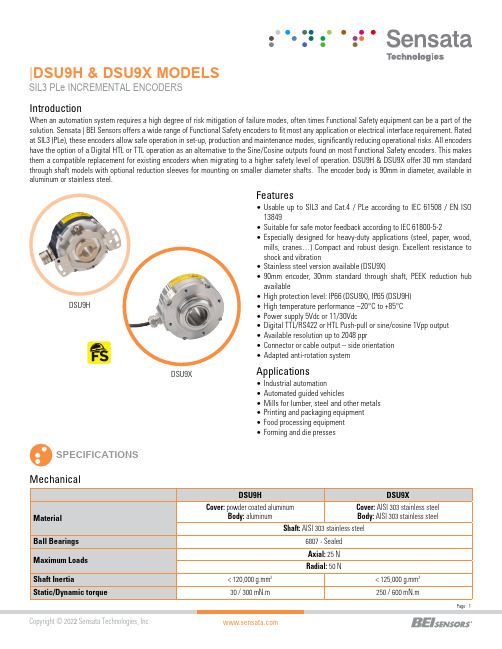
|DSU9H & DSU9X MODELSSIL3 PLe INCREMENTAL ENCODERS SPECIFICATIONSFeatures•Usable up to SIL3 and Cat.4 / PLe according to IEC 61508 / EN ISO 13849•Suitable for safe motor feedback according to IEC 61800-5-2•E specially designed for heavy-duty applications (steel, paper, wood,mills, cranes…) Compact and robust design. Excellent resistance to shock and vibration•Stainless steel version available (DSU9X)•90mm encoder, 30mm standard through shaft, PE E K reduction hub available•High protection level: IP66 (DSU9X), IP65 (DSU9H)•High temperature performance –20°C to +85°C •Power supply 5Vdc or 11/30Vdc•Digital TTL/RS422 or HTL Push-pull or sine/cosine 1Vpp output •Available resolution up to 2048 ppr•Connector or cable output – side orientation •Adapted anti-rotation systemIntroductionApplications•Industrial automation•Automated guided vehicles•Mills for lumber, steel and other metals •Printing and packaging equipment •Food processing equipment •Forming and die pressesDSU9XWhen an automation system requires a high degree of risk mitigation of failure modes, often times Functional Safety equipment can be a part of the solution. Sensata | BEI Sensors offers a wide range of Functional Safety encoders to fit most any application or electrical interface requirement. Rated at SIL3 (PLe), these encoders allow safe operation in set-up, production and maintenance modes, significantly reducing operational risks. All encoders have the option of a Digital HTL or TTL operation as an alternative to the Sine/Cosine outputs found on most Functional Safety encoders. This makes them a compatible replacement for existing encoders when migrating to a higher safety level of operation. DSU9H & DSU9X offer 30 mm standard through shaft models with optional reduction sleeves for mounting on smaller diameter shafts. The encoder body is 90mm in diameter, available in aluminum or stainless steel.(A)Continuous max. speed – ½ max. load – according to ISO 281: 1990, L10(B)Device must be supplied by a Class 2, LPS or SELV limited energy source.(C) UL listed:Electrical ConnectionsNote: All connections are UL certified, except G3 and GP RESOLUTIONS1024 2048DSU9H – radial cable and 20mm reduction hubDSU9X- radial M23 connector - IP66 optionCOUPLING INTERFACE Stator coupling kit M9445/045Tether arm kit M9445/046For a safe installation according to the required safety level needed in the application, refer to the user safety User Manual.The safety User Manual provides the technical information (drawings, electrical data, etc...) for a safe integration.A quick installation guide is provided with each encoder for use by the technician who installs the device on the equipment.GENERAL NOTESORDERING OPTIONSContact the factory for special versions, ex: resolution, connection, flange...* Parts mounted on encoder and fasteners included in the encoder box.AGENCY APPROVALS & CERTIFICATIONSBEI Sensors SASSensata TechnologiesEspace Européen de l’Entreprise9, rue de CopenhagueB.P. 70044 SchiltigheimF 67013 Strasbourg CedexTélFaxMailWeb: +33 (0)3 88 20 80 80: +33 (0)3 88 20 87 87:****************************: Americas+1 (800) 350 2727*******************Europe, Middle East & Africa +33 (3) 88 20 8080****************************Asia Pacific*************************.com China +86 (21) 2306 1500Japan +81 (45) 277 7117Korea +82 (31) 601 2004India +91 (80) 67920890Rest of Asia +886 (2) 27602006 ext 2808Page 7CONTACT USSensata Technologies, Inc. (“Sensata”) data sheets are solely intended to assist designers (“Buyers”) who are developing systems that incorporate Sensata products (also referred to herein as “components”). Buyer understands and agrees that Buyer remains responsible for using its independent analysis, evaluation and judgment in designing Buyer’s systems and products. Sensata data sheets have been created using standard laboratory conditions and engineering practices. Sensata has not conducted any testing other than that specifically described in the published documentation for a particular data sheet. Sensata may make corrections, enhancements, improvements and other changes to its data sheets or components without notice.Buyers are authorized to use Sensata data sheets with the Sensata component(s) identified in each particular data sheet. HOWEVER, NO OTHER LICENSE, EXPRESS OR IMPLIED, BY ESTOPPEL OR OTHERWISE TO ANY OTHER SENSATA INTELLECTUAL PROPERTY RIGHT, AND NO LICENSE TO ANY THIRD PARTY TECHNOLOGY OR INTELLECTUAL PROPERTY RIGHT, IS GRANTED HEREIN. SENSATA DATA SHEETS ARE PROVIDED “AS IS”. SENSATA MAKES NO WARRANTIES OR REPRESENTATIONS WITH REGARD TO THE DATA SHEETS OR USE OF THE DATA SHEETS, EXPRESS, IMPLIED OR STATUTORY, INCLUDING ACCURACY OR COMPLETENESS. SENSATA DISCLAIMS ANY WARRANTY OF TITLE AND ANY IMPLIED WARRANTIES OF MERCHANTABILITY, FITNESS FOR A PARTICULAR PURPOSE, QUIET ENJOYMENT, QUIET POSSESSION, AND NON-INFRINGEMENT OF ANY THIRD PARTY INTELLECTUAL PROPERTY RIGHTS WITH REGARD TO SENSATA DATA SHEETS OR USE THEREOF.All products are sold subject to Sensata’s terms and conditions of sale supplied at SENSATA ASSUMES NO LIABILITY FOR APPLICATIONS ASSISTANCE OR THE DESIGN OF BUYERS’ PRODUCTS. BUYER ACKNOWLEDGES AND AGREES THAT IT IS SOLELY RESPONSIBLE FOR COMPLIANCE WITH ALL LEGAL, REGULATORY AND SAFETY-RELATED REQUIREMENTS CONCERNING ITS PRODUCTS, AND ANY USE OF SENSATA COMPONENTS IN ITS APPLICATIONS, NOTWITHSTANDING ANY APPLICATIONS-RELATED INFORMATION Made in FranceACCESORIES。
GU641B简介
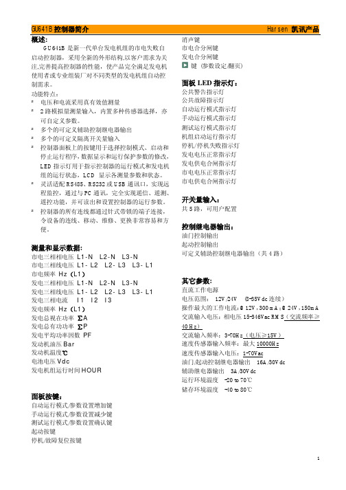
GU641B 是新一代单台发电机组的市电失败自 启动控制器,采用全新的外形结构,以客户需求为关 注,完善提高控制器的性能,使产品完全满足发电机 使用者或专业组装厂对不同类型的发电机组自动控 制需求。 功能特点: ² 电压和电流采用真有效值测量 ² 2 路模拟量测量输入,内置多种传感器选择,亦
Harsen 凯讯产品
开关量输入:
共 5 路,可用户配置
控制继电器输出:
油门控制输出 起动控制输出 可定义源 电压范围: 12V/24V (8-35Vdc 连续) 操作最大的工作电流:@12V,300 mA;@24V,150mA 交流输入电压:相电压 15-346Vac RMS(交流频率≥ 40 Hz) 交流输入频率:3-70Hz(电压≥15V) 速度传感器输入频率:最大 10000Hz 速度传感器输入电压:1-70Vac 油门/起动控制继电器输出 16A/30Vdc 辅助继电器输出 3A/30Vdc 运行环境温度 -20 to 70℃ 储存环境温度 -40 to 80℃
面板按键:
自动运行模式/参数设置增加键 手动运行模式/参数设置减少键 测试运行模式/参数设置确认键 起动按键 停机/故障复位按键
消声键 市电合分闸键 发电合分闸键
键 (参数设定/翻页)
面板 LED 指示灯:
公共警告指示灯 公共故障指示灯 自动运行模式指示灯 手动运行模式指示灯 测试运行模式指示灯 机组启动运行指示灯 停机/停机失败指示灯 发电电压正常指示灯 发电供电合闸指示灯 市电电压正常指示灯 市电供电合闸指示灯
1
GU641B 控制器简介 典型接线图:
Harsen 凯讯产品
2
GU641B 控制器简介
外型尺寸图:
北京南凯公司RTU产品介绍20100316

1. 遥测采集
每个遥测采集模块板最多可以接 个交流量 12个直流量 每个遥测采集模块板最多可以接72个交流量, 12个直流量, 这样保 遥测采集模块板最多可以接72个交流量, 个直流量, 证了模块板的处理性能. 交流量可以是电压和电流. 证了模块板的处理性能. 交流量可以是电压和电流. 遥测采集单元每 周波采集32个点 周波采集32个点. 个点.
• RTU(Remote Terminal Unit)-NK5730 远动终端是北京 Unit)南凯自动化系统工程有限公司研制生产的远程终端
产 品 简 介
控制系统。 • RTU-5730是一体化现场智能监控设备,通过程序设 RTU-5730是一体化现场智能监控设备,通过程序设 计可完成复杂的数据采集、逻辑和过程控制等功能, 选择适宜的通讯方式和协议可实现远程测控。在制 造中,采用工业质量标准,能适应地理环境恶劣无 人值守的应用方式,可广泛用于工业自动化领域。 模块化的组装方便了实际应用。
12. 仪表接入
现场需要通过通信线路接入特殊功能的仪表,议器 现场需要通过通信线路接入特殊功能的仪表 议器. 接入方式可 议器 以使用串口通信或者网络通信. 通信规约一般是通用的Modbus规约 规约, 以使用串口通信或者网络通信 通信规约一般是通用的 规约 或者根据仪表或议器的要求配置规约。 或者根据仪表或议器的要求配置规约。
设备特点
• 多通道通信安全高效 内部双can,外部以太网4 内部双can,外部以太网4口 • 多方式外部仪表接入 RS485,RS232,以太网,CAN接入.通信规约支持modbus,101,等 RS485,RS232,以太网,CAN接入.通信规约支持modbus,101,等 • 以太网路由交换 内置zebra模块 内置zebra模块 • 不间断电源安全可靠 电源模块在外部电源和蓄电池之间无间断自动切换, 电源模块在外部电源和蓄电池之间无间断自动切换,保证设备长期连 续运行. 续运行. • 多机备用模式 通信主模块支持在线多设备备用,安全可靠, 通信主模块支持在线多设备备用,安全可靠,数据不会丢失
柴油发电机组并机简介

型号/功能 最多并机数 输出数 输入数 传感器数 RS232 RS485
GU660A
12
6
11
4
可选配 可选配
DSE7510
深海
DSE8610
DSE8710
DSE8110
功能对比
型号/功能 最多并机数 输出
DSE7510
16
5
DSE8610
32
8
DSE8710
32
8
DSE8810
32
8
输入
9 11 12 11
• LYC550G(侧置式控制柜) • 发动机:KTAA19-G6A 发电机:HCI544FS • 控制器:HGM7120A 断路器:施耐德NS1600N
• LYC710G(并机后经输出柜输出) • 发动机:KTA38-G2B 发电机:EG400S-640N • 控制器:GU660A 断路器:长征MA40 • 输出柜断路器:正泰 NA1
具有 具有
RS485
具有 具有
四、并机原理简述
• 并机三要素:相序、电压、频率一致方可进行。
五、实现并机的主要组成器件
机组部分需注意
• 1、几台机组并机?几台机组是否在一起? 确定在制作时几个控制柜相连
• 2、机组与控制柜距离? 确定导线束所需长度
并机柜部分需注意
• 1、控制器型号 • 2、断路器型号(默认固定式断路器) • 3、控制柜其它要求(如:提供机组运行无
③当带载的发电机组报警停机时,剩余未开机的 机组全部自动开机。
HGM6510
众智
HGM9510
功能对比区别
型号/功 能
HGM6510
HGM9510
最多并 机数
- 1、下载文档前请自行甄别文档内容的完整性,平台不提供额外的编辑、内容补充、找答案等附加服务。
- 2、"仅部分预览"的文档,不可在线预览部分如存在完整性等问题,可反馈申请退款(可完整预览的文档不适用该条件!)。
- 3、如文档侵犯您的权益,请联系客服反馈,我们会尽快为您处理(人工客服工作时间:9:00-18:30)。
概述:
GU304A是发动机的安全保护模块,用于发动机的安全保护和运行状态、参数显示。
模块外加锁匙开关,可以用于发动机的启动运行和停机,模块测量显示多个发动机参数,在发动机运行期间,发生警告事件,模块面板LED显示相关警告;发生故障事件,模块面板LED显示相关故障,关闭油门输出,发动机停机。
其主要特征:l采用微处理器为核心;
l通过面板按键和数码管可以灵活设置运行保护参数;
l测量显示发动机的电池电压、转速、油压、水温、运行时间等参数;
l可程序设定发动机的油门类型;
l内置多种油压和温度传感器类型供用户选择;
l控制器采用DIN72标准外壳,所有连线都通过针式带锁的端子连接,令设备的连线、移动、维修、更换容易和方便;
模块面板状态LED指示灯:
当模块安全检测延时时间计时结束,模块检测到油压开关信号有效时,此LED指示灯亮,表示发动机发生低油压故障。
当模块安全检测延时时间计时结束,模块检测到发动机的运行速度大于额定速度的10%时,LED指示灯亮,表示发动机超速故障。
当发动机运行时,模块检测到低温位开关信号有效时,此LED指示灯亮,表示发动机燃油箱油位处于低油位状态。
当模块接通工作电源,检测到急停开关信号有效时,此LED指示灯亮,表示发动机处于急停状态,报警继电器不动作。
模块检测显示参数:
l电池电压 Vdc
l发动机运行时间 Hour
l发动机冷却水温℃(信号来自发动机的水温传感器)
l发动机机油压力 Kpa (信号来自发动机的油压传感器)
l发动机运行速度 RPM (信号来自发电机的交流电压)
所有参数均以LED数码管显示,数码管上的LED指示灯指示所选择显示的相关参数。
单个四位数码管以自动循环方式逐一显示所有参数。
故障停机保护:
(故障停机保护,指故障发生确认时,相应的故障指示亮,油门输出继电器分开,发动机停机,报警继电器闭合输出,故障状态锁定,直至控制器的工作电源断开)
l低油压故障
l高水温故障
l超速故障
警报保护:
(警报保护,指警报发生确认时,相应的故障指示亮,发动机继续运行,报警继电器闭合输出,状态不锁定,当警报解除时,相关显示和输出即解除)
l半油位
l低油位
l高箱温
l充电失败
l低电池电压值
可设置的运行参数:
供油阀种类(0常闭型/1常开型)
速度传感器种类(0~1)
齿数(1~999)
极对数(1~4)
油压传感器种类(0~3)
水温传感器种类(0~3)
安全监察延时时间(0~600秒)
超速故障值(0~9999RPM)9999 (不设)
高水温故障值(70~160℃)
低油压故障值(50~300 Kpa)
低电池警报(1~25V)0 (不设)
其它参数:
直流工作电源
电压范围:12V/24V(8-32V连续)
交流输入频率:5-70HZ(50V≤电压≤300V)
速度传感器输入:最大10000Hz (1V≤电压≤70V)
继电器输出:3A/30VDC
运行环境温度-20 to 70℃
储存环境温度-40 to 80℃
外型尺寸图:
操作面板W72mm×H72mm
安装开孔口W67mm×H67mm
厚度D82.5mm(未连线)
典型接线图:
版本:048A081211。