YT-1000定位器的反馈调试方法
电-气阀门定位器 YT-1000系列 说明书
电-气阀门定位器YT-1000系列使 用 说 明 书YTC Ver 1.02电-气阀门定位器 YT-1000系列说明书概要2安全注意事项2使用注意事项2质保期限2产品简介3标牌内容3特点4选型代码4主要参数5结构图6动作原理7外形尺寸8YT-1000L的外形尺寸图8 YT-1000R的外形尺寸图9安装10注意事项10安装时必要的工具10 YT-1000L的安装10利用支架安装YT-1000L11 YT-1000R的安装14利用支架安装YT-1000R15配管18注意事项18空压条件18配管条件18执行机构和气管的连接19电源连接-耐压防爆型 21耐压防爆型电线管的连接21耐压封闭型电缆的连接21接线端子连接22电源连接-本质安全型 22接线端子的连接22调节23零点调节23量程调节23自动/手动开关(旁路开关)24底座调节24节流孔调节25产品维护和检查25故障诊断和措施26目 录说明书概要z请充分阅读此说明书后,进行产品的安装,调试和使用。
z此说明书的内容未经事先通知的情况下可变。
z此说明书的内容未经我公司同意不得任意更改或替换。
z在此说明书未经说明的事项中出现的问题,请跟我公司或代理商联系。
z此说明书指定的参数适用于指定的型号和使用条件,有可能不能满足特殊的条件。
z为了产品的性能改进或升级,产品的参数,结构,部件等发生变动时,有可能没有反映到此说明书。
安全注意事项z为了安装人员,产品,系统的安全,安装本产品时请务必遵守本说明书注明的安全事项。
如果不正确遵守本说明书的安全事项,我公司不能保证其安全。
z因用户任意进行改造或维修本产品而发生的人身伤害或物质损失,我公司不给予赔偿。
需要维修或改造本产品时,请事先跟我公司联系。
z本产品是控制阀附件。
操作或运行时必须熟记相应控制阀的使用说明。
使用注意事项z搬运,安装或使用中,对产品过大的震动或撞击会成为产品故障的原因。
z超过规定参数范围使用也会成为产品故障的原因。
YT-1000L使用说明书

YT-1000L型电-气阀门定位器YT-1000L型电-气阀门定位器用于采用4-20mA或等信号范围的模拟信号的电动控制器及控制系统的气动回转阀执行机构的回转操作。
1.结构2.安装2.1安装到执行机构的范例2.2反馈杆的连接1.安装到当输入信号为50%时阀杆和反馈杆成直角的位置上。
2.安装到偏差角在10度-30度内位置上。
2.3正向动作与反向动作〈正向动作〉〈反向动作〉2.4通气管的连接2.1.用管子彻底清除杂物。
2.用洁净气体彻底清除潮气和尘埃。
3.用YT-200过滤调节器不断保持供气压力。
4.在将双向动作型作为单向动作型使用时,不是堵塞OUT1就是堵塞OUT2,而且还要拆下压力表来断开其连接。
4.电气接线1.分别将调整器的(+)(-)输出端和定位器接线盒的(+)(-)输入断连接起来。
2.至于防爆型,压力密封导线管线连接型和压力密封充填型都可适用。
(1)在压力密封充填型中使用电缆密封套(电缆外径=90-11)。
(2)在导线管线连接型中使用PF1/2(G1/2)规格。
3.关上接线盒盖,锁上锁定螺丝。
4.在接线板上有只备用螺栓。
5.调整1.在开始调整前检查下列。
检查管道与压力输送口和OUT1及OUT2口正确连接。
2.检查导线与(+)、(-)极和接地端正确连接。
3.检查执行机构与定位器牢固连接。
4.检查导阀自动/手动转换开关螺丝松紧(顺时针完全紧固)。
5.检查内反馈跨距调整杆被安装到正确的位置上(正向或反向)6.检查凸轮面(正向或反向)的正确使用和发兰盘螺母牢固锁紧。
5-1零位调整1.将信号设定在冲程开始信号(4mA),然后顺时针或逆时针转动零位调整器。
2.如果是弹簧执行机构,检查它是否设在零位标准压力上。
如否,则重复进行零点调整。
5-2跨距调准1.调整跨距范围以便执行机构分别按0%和100%输入信号停在冲程的0%和100%位置上。
2.检查零位,重复进行零位跨距调整。
零位跨距调整采用1/2分隔范围。
定位器YTC-1000使用指导书
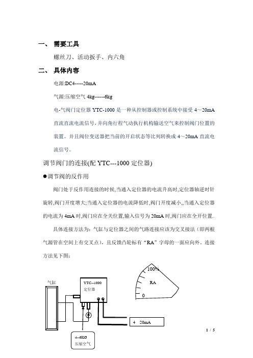
一、 需要工具螺丝刀、活动扳手、内六角二、 具体内容电源:DC4-----20mA气源:压缩空气4kg------6kg电-气阀门定位器YTC-1000是一种从控制器或控制系统中接受4~20mA 直流直流电流信号,并向角行程气动执行机构输送空气来控制阀门位置的装置。
并且阀位变送器把当前的开启状态等比列转换成4~20mA 直流电流信号。
调节阀门的连接(配YTC---1000定位器)调节阀的反作用阀门处于反作用连接的时候,当通入定位器的电流升高时,定位器轴逆时针旋转,阀门开度增大;当通入定位器的电流降低时,阀门开度减小,,当通入定位器的电流为4mA 时,阀门应在全关位置,输入信号为20mA 时,阀门应在全开位置.具体连接方法为:气缸与定位器之间的气路连接应该为交叉接法(即两根气源管在空间上有交叉点),且反馈凸轮标有“RA ”字母的一面应向外。
连接方法见下图:100%RA●调节阀门的正作用阀门处于正作用连接的时候,当通入定位器的电流升高时,定位器轴顺时针旋转,阀门开度减小,在定位器通入20mA 电流时,阀门全关;当通入定位器的电流降低时,阀门开度增大,在电流为4 mA 时,阀门全开.具体连接方法为:气缸与定位器之间的气路连接应该为平行接法(即两根气源管在空间上无交叉点),且反馈凸轮标有“DA ”字母的一面应向外。
连接方法见下图:DA100%● 调节阀的零点调整与量程标定调节阀门的反作用输入信号4mA,调节零点,使阀门在全关位置,输入信号为20mA 时,调节量程,使阀门在接近全开的位置,输入信号为4m A 时,重新调节零点,使阀门在全关位置,输入信号为20mA 时,重新调节量程,使阀门在接近全开位置,反复几次,使4mA信号对应阀门全关,20mA信号对应全开位置。
调节阀门的正作用输入4mA信号,使阀门对应全开位置,输入信号为20mA时,调节量程,使阀门在接近全关的位置,输入信号为4 mA时,重新调节零点,使阀门在全开位置,输入信号为20mA时,重新调节量程,使阀门在接近全开位置,反复几次,使4mA对应阀门全开,20mA对应阀门全关.具体调整步骤:(以反作用接法为例)(1)零点:一般在4mA计算机显示0%时调整,逆时针调整零罗盘如上图所示,零点向关方向偏移,顺时针方向调整零点向开放向偏移。
YT-1000R定位器调试方法
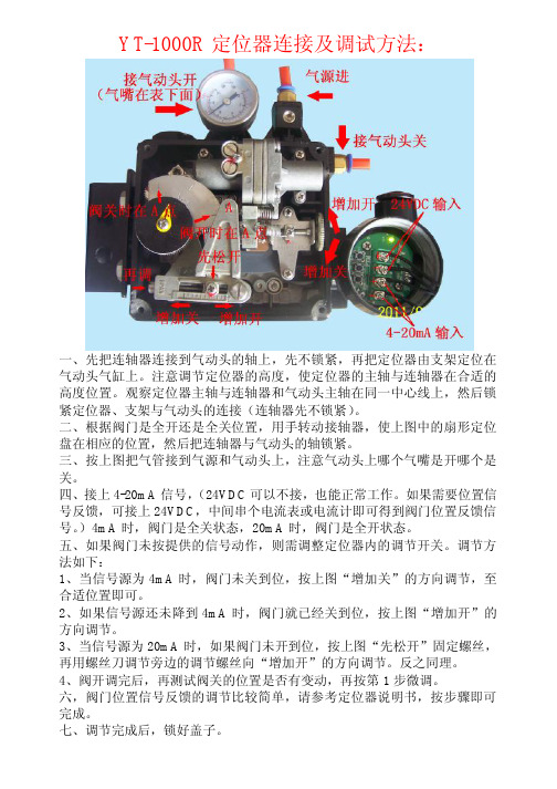
YT-1000R定位器连接及调试方法:
一、先把连轴器连接到气动头的轴上,先不锁紧,再把定位器由支架定位在气动头气缸上。
注意调节定位器的高度,使定位器的主轴与连轴器在合适的高度位置。
观察定位器主轴与连轴器和气动头主轴在同一中心线上,然后锁紧定位器、支架与气动头的连接(连轴器先不锁紧)。
二、根据阀门是全开还是全关位置,用手转动接轴器,使上图中的扇形定位盘在相应的位置,然后把连轴器与气动头的轴锁紧。
三、按上图把气管接到气源和气动头上,注意气动头上哪个气嘴是开哪个是关。
四、接上4-20mA信号,(24VDC可以不接,也能正常工作。
如果需要位置信号反馈,可接上24VDC,中间串个电流表或电流计即可得到阀门位置反馈信号。
)4mA时,阀门是全关状态,20mA时,阀门是全开状态。
五、如果阀门未按提供的信号动作,则需调整定位器内的调节开关。
调节方法如下:
1、当信号源为4mA时,阀门未关到位,按上图“增加关”的方向调节,至合适位置即可。
2、如果信号源还未降到4mA时,阀门就已经关到位,按上图“增加开”的方向调节。
3、当信号源为20mA时,如果阀门未开到位,按上图“先松开”固定螺丝,再用螺丝刀调节旁边的调节螺丝向“增加开”的方向调节。
反之同理。
4、阀开调完后,再测试阀关的位置是否有变动,再按第1步微调。
六,阀门位置信号反馈的调节比较简单,请参考定位器说明书,按步骤即可完成。
七、调节完成后,锁好盖子。
yt1000阀位变送器调试说明

阀位变送器调试说明一、阀位变送器的接线工作原理:当输入端送入4~20mA DC电流控制执行结构,执行机构带动外接检测元件(旋转可变电阻)移动,反馈端相应输出4~20mA DC电流。
变送器可自动判别正、反作用。
第一次调试或阀门运行过程变送器输出错乱,必须重新调整,调整之前需重新认定外接可变电阻器位置,方法如下:1,输入端送入12mA电流,待阀门稳定2,将可变电阻器与阀门脱开3,旋转可变电阻器轴,用万用表测量中间引脚与两边引脚阻值,应为可变电阻器标称值的一半4,输入端电流撤除,阀门回位,将可变电阻器与阀门重新连接。
二、反向作用电流调整1、输入端外接4~20mA DC电流源,反馈端接+24VDC稳定电源,串接电流表(大于20maA),接线参考上图。
2、本变送器主要调整4~20mA DC之间的5个位置点,其余由变送器计算输出,这5个点分别是4mA DC、8mA DC、12mA DC、16mA DC、20mA DC。
送上电源(+24V),LED频闪5次,输出4 mA DC,进入调整状态(如果已经调整过则LED不频闪,如果希望重新调整,按住“CTRL”键,持续三秒钟以上,待LED开始频闪5次,立即松开按键)。
3、输入端送入4mA DC电流,确认阀门位置合适时,点动“CTRL”键,LED频闪1次,则该位置点调整完毕。
输出电流自动增加至8mA DC 4、输入端送入8mA DC电流,点动“CTRL”键,LED频闪1次,则该位置调整完毕。
输出电流自动增加至12mA DC5、依次送入12mA DC、16 mA DC并确认。
6、输入端送入20 mA D C电流,点动“CTRL”键,LED频闪8次,表示调整已完成,进入自动跟踪状态,并输出该位置点电流20 mA DC。
7、改变输入端送入电流,阀门位置改变输出电流值相应改变。
三、输出电流值调整1、由于电子元件特性的差异,每个变送器输出电流会有所不同,因此必须调整。
例如:8 mA DC位置点,输出为7.9 mA DC。
YT-1000系列使用说明书
-3-
电-气阀门定位器
YT-1000系列
特点
z 抗震性能高,在震动大的现场动作也很稳定。 z 经过100万次以上的动作测试和抗震测试,确保了产品的稳定性。 z 反应速度快,精度高。 z 简单调整,就可以实现1/2范围行程控制。 z 空气消耗量少,节能性好。 z 正/反作用可方便转换。 z 零点,量程调节非常简单。 z 反馈连接非常简单。
- 10 -
电-气阀门定位器
YT-1000系列
利用支架安装YT-1000L
(1) 制作可以正确连接在执行机构支架上的定位器支架。制作支架时要考虑的核心事项如下:
① YT-1000L反馈杆在阀门行程50%的位置要水平。 (参考本说明书10页第(7)项内容)
② 在执行机构和阀杆连接件上的反馈杆连接棒,必须要连接在阀门行程和刻在反馈杆上的刻 度一致的位置。(参考本说明书11页第(8)项内容)
-7-
电-气阀门定位器
外形尺寸
YT-1000L的外形尺寸图
YT-1000系列
< 耐压防爆型YT-1000L的外形尺寸图>
<本质安全型YT-1000L的外形尺寸图> -8-
电-气阀门定位器
YT-1000R的外形尺寸图
YT-1000系列
< 耐压防爆型YT-1000R的外形尺寸图>
<本质安全型YT-1000R的外形尺寸图> -9-
- 当用户任意分解产品或没有正确进行维护而产生的问题。 - 没有正确运输,保管而产生的问题。 - 超过产品额定参数使用而产生的问题。 - 没有正确安装而产生的问题。 - 因火灾,地震,暴风,洪水,雷电和其它自然灾害或暴动,战争,放射能等天灾人祸而
YTC定位器YT-1000R_(C)调节
使用手册(YT-1000R/角行程)Young Tech Co., Ltd.1. 简介电-气阀门定位器YT-1000R是一种从控制器或控制系统中接受4~20mA电流信号,并向气动执行机构输送空气来控制阀门开度的装置。
2. 特征- 在5~200Hz范围内无共振现象。
- 不用更换零件只需简单操作即可进行1/2范围内的分程控制。
- 零调节和量程调节非常简单。
- 正作用和反作用,单作用和双作用之间可方便转换。
- 反馈杆连接非常简单。
- 反应速度快而准确。
- 空气消耗量小,经济性好。
- 在小型执行器也可利用先导阀的节流孔来防止振动现象。
3. 参数型号动作形式防爆等级反馈杆喷嘴连接形式环境温度选用配件1选用配件2 YT-1000R单作用 ExdmIIBT5 M6×40L小于90㎤ PT -20℃~70℃标准指示器无双作用 ExdmIICT5 M6×63L 90~180㎤ NPT -20℃~120℃圆顶指示器 +PTM(内置)ExiaIIBT6 M8×40L大于180㎤ -40℃~70℃ +PTM9(外置)不防爆 M8×63L +L/S(内置)NAMUR +L/S(外置)+PTM+L/S(内置) <备注>以大气温度20℃,绝对压760㎜Hg,相对湿度65%为基准。
本产品的基本配置适用于耐压封闭防爆(ExdmⅡBT6)及容器保护等级IP66。
以单作用(Single Acting)为标准。
用量程调节旋扭可达到1/2范围内的分程控制。
标准类型以外的产品请另询问。
5. 结构图6. 动作原理为了改变阀门的位置增加输入电流。
由①力矩马达发生力,使②挡板和③喷嘴之间距离增加从而喷嘴背压急剧减小。
⑤阀芯向上移动,同时⑦气门被打开,把出口1导管空压送到⑩执行机构。
增加⑪执行机构腔内的压力而使⑫执行机构轴开始旋转。
随着⑫执行机构轴开始旋转,与反馈杆连接的反馈弹簧被拉伸。
当定位器的输入信号产生的电磁力矩与反馈弹簧的力矩相平衡时,⑫执行机构的轴停止旋转。
yt1000阀门定位器原理
yt1000阀门定位器原理yt1000阀门定位器是一种用于调节控制阀门位置的设备,它通过测量和反馈阀门执行器的位置,实现对阀门的精确控制。
本文将介绍yt1000阀门定位器的原理及其工作过程。
一、原理概述yt1000阀门定位器基于电动阀门执行器和位置传感器的组合,实现对阀门位置的精确测量和控制。
其原理基于负反馈控制系统,通过持续的位置反馈和调整,使阀门保持在预设位置,从而实现对流体的流量和压力的精确调节。
二、工作过程1. 位置传感器yt1000阀门定位器内置了高精度的位置传感器,用于实时测量阀门执行器的位置。
传感器通常使用非接触式的技术,如霍尔传感器或磁敏传感器。
当阀门执行器移动时,传感器会感知到位置的变化,并将该信息传递给控制系统。
2. 控制系统yt1000阀门定位器配备了先进的控制系统,用于处理位置传感器的反馈信号,并根据设定值进行阀门位置的调整。
控制系统通常由微处理器和相关电路组成,能够实现高速、精确的控制。
3. 电动阀门执行器yt1000阀门定位器与电动阀门执行器紧密结合,通过控制执行器的运动来实现对阀门位置的调节。
电动阀门执行器通常由电机、齿轮传动装置和机械连接杆组成。
执行器接收控制系统的指令,通过电机的转动来改变阀门的开度。
4. 反馈控制yt1000阀门定位器的核心是负反馈控制系统。
在设定值和实际位置之间存在差值时,控制系统会根据该差值来调整阀门位置。
具体而言,如果阀门偏离设定值,控制系统会相应地发送指令,调整电动阀门执行器的运动,使阀门趋近于设定位置。
反之,当阀门接近预设位置时,控制系统将减小或停止对执行器的操作,以避免过冲。
三、优势与应用yt1000阀门定位器具有以下优势:1. 高精度控制:通过精确的位置反馈和调整,yt1000阀门定位器能够实现对阀门位置的精确控制,可满足对流量和压力更高要求的应用。
2. 快速响应:借助先进的控制系统,yt1000阀门定位器能够快速地对位置偏差进行反馈和调整,实现对流体的实时控制。
YT-1000RDnF定位器智能模块使用调试方法
认。
5.反 馈信号 50‰ (12nlA)位 置调整
阀门处于需要信号 50%0(1⒛A)的 位置,按 “+” 或 “-” 键调整 电流 ,使 电流值符合要求 ,然 后按一下上 图最右边 的按键 。
观察 电流表读数 :如 电流表读数从 12lnA跳 到 16mA左 右 ,即 表示需要反馈 信号 50%0(12mA)的 位置 已确认完毕。模块等待反馈信号 75%0(1GmA)的 位置
值。
2.使 模块进入调试状态
按住如上 图所示最右边一个按键不放待模块上 的指示灯亮起 ,然 后放开该
按键 9指 示灯 闪烁 即表示模块 已进入调试状态 。
观察电流表读数 :此
时电流表读数应为
4mA,如
有偏差 ,可
按
“
+”
键或
“ -”
键调整 电流,使 电流值符合要求。
3.反馈信号 0%0(4mA)位 置调整 阀门处于原始 0%。 (4mA)的 位置 。按 “+” 或 “-” 键调整 电流 ,使 电流值 符合要求 ,然 后按一下上 图最右边 的按键 。 观察 电流表读数 :如 电流表读数从 4献 膨晤刂8mA左 右 ,即 表示需要反馈信 号 0%0(4mA)的 位置 已确认完毕 。模块等待反馈信号 25%。 (8mA)的 位置确认。
电气 阀 门定位 器智 能模块使 用调 试方 法
一 、电气连接
如图所示 :PTM端 直流 γV稳 压 电源 ,若 串接 电流表或 电流传感器 ,
可观察到 电流变化 。 二 、使模 块 正 常工作
4~20mAsigna1hput
powcrsourcc DC24v
YT-1000L系列电气气动定位器用户手册说明书
Electro-pneumatic PositionersYT-1000L SeriesUSER'S MANUALYTC Ver 1.01Table of ContentsIntroduction3 Manufacturer Warranty3 Product Description4 Main Features and Functions4 Operation Logic4 Label Description5 Suffix Symbol5 Specification6 Parts and Assembly7 Dimension8 YT-1000L: Explosion-Proof Type8 YT-1000L: Intrinsically Safe Type8 Installation9 Safety Waring9 Tools for Installation9 YT-1000L Installation9 Piping Connection12 Supply Pressure Condition12 Pipe Condition12 Piping Connection with Actuator12 Power Connection13 Connection - Connection Port13 Connection - Cable Gland13 Connection - Power14 Connection - Ground14 Adjustment15 Adjustment - Zero15 Adjustment - Span15 Adjustment - A/M Switch (Automatic/Manual)15 Adjustment - Seat Adjuster15 Adjustment - Orifice16 Troubleshooting17IntroductionThank you for choosing YTC product. Each product is fully inspected after the production to offer you the highest quality. In order to fully utilize the product, we strongly recommend users to read this manual carefully and understood.z The manual should be provided to the end user.z The manual can be changed or revised without any prior notice. Any changes in product's specification, structure, and/or any components may not result immediate revised version of the manual.z The manual should not be duplicated or reproduced for any purpose without any approval from Young Tech Co., Ltd, South Korea.Manufacturer Warranty- For the safety, it is imperative to follow instructions in the manual. It is not manufacturer's liability for any damages which caused by users' negligences.- It is not manufacturer's liability for any damages or accidents which resulted by any alteration or modification of the product and parts. If alteration ormodification is necessary, please contact the manufacturer directly.- Manufacturer warrants the product from the date of original retail purchase of the product for one (1) year, except as otherwise stated.- Manufacturer warranty will not cover the products that the product have been subjected to abuse, accident, alteration, modification, tampering, negligence,misuse, faulty installation, lack of reasonable care, repair or service in any waythat is not contemplated in the documentation for the product, or if the modelor serial number has been altered, tampered with, defaced or removed;damages that occurs in shipment, due to act of God, failure due to powersurge, and cosmetic damage. Improper or incorrectly performed maintenance or report voids this Limited Warranty.- For detailed warranty information, please contact the corresponding local Young Tech Co., Ltd office or main office in South Korea.Product DescriptionMain Features and Functionsz It is designed for high durability and performance in high vibration environment.z Durability has proven after testing of 1 million times, at least.z Response time is very short and accurate.z Simple part change can set 1/2 Split Range.z It is economical due to less air-consumption.z Direct/Reverse action can be set easily.z Zero & Span adjustment process is simply.nozzle(③) and the flapper(②) increases, which results pressure in upper spool(⑤) exhaustion. This would cause spool(⑤) to rise upward. As the spool(⑤) rises, the air pressure will be supplied to the actuator(⑩). As the actuator's inner pressure increases, the actuator stem(⑫) will move. The movement will be transferred to cam(⑭) and pulls the span spring(⑮). The span spring(⑮)'s force will be balanced with torque motor(①), and this would cause to move flapper(②) to the normal position and reduce the gap between the nozzle(③). As the air pressure exhaustion level decreases through the nozzle(③), the pressure level in upper spool(⑤) increases again. The spool(⑤) would come back to the normal position and block the seat(⑦) which would lead to block the supply air from the actuator(⑩). When the actuator(⑩) stops the movement, the positioner would come back to the normal position. <Figure 1>Suffix SymbolYT-1000L series follows suffix symbols as follows.YT-1000L════════════════════════════════Motion Type S :LinearD :Double════════════════════════════════Explosion Proof m :Ex dm IIB T5C :Ex dm IIC T5:Ex ia IIB T6in :Non-Explosion════════════════════════════════Feedback Lever 1 :10 ~ 40mm:30∼ 70mm23 :60 ∼ 100mm4 : 100 ∼ 150mm════════════════════════════════Orifice 1 : Ø1Ø22:3 : None════════════════════════════════Connection Type 1 :PT2 :NPT════════════════════════════════Ambient Temperature S :-20 ~ 70℃H :-20 ~ 120℃L :-40 ~ 70℃════════════════════════════════* For special specification, please contact our sales department.Specification* Tested under ambient temperature of 20℃, absolute pressure of 760mmHg, and humidity of 65%.Please contact us for more detailed specification.* 1: For 1/2 Split Control, it can be applied by adjusting zero and span.*2: For inquiry regarding strokes under 10mm or above 150mm, please contact YTC.* 3: YT-1000L has different types of explosion proof certificates. Please make sure to check explosion proof grade.Parts and AssemblyInstallationSafety WarningWhen installing positioner, please ensure to read and follow safety instruction.z All input and supply pressure to valve, actuator, and other related devices must be turned off.z Use bypass valve or other equipment to avoid entire system "shut down."z Make sure there is no remaining pressure in the actuator.Tools for installation①Hexagonal wrench②Screw drivers (+) & (-)③Spanners for hexagonal-head boltsYT-1000L installationYT-1000L should be installed on linear motion valve such as globe valve or gate valve using spring return type diaphragm or piston actuator. Before installation, be sure to check for following installation components.①YT-1000L main body②Feedback lever and lever spring③Flange nut (bottom side of YT-1000L)④4 pcs. of hexagon head bolts (M8 X 1.25P)⑤4 pcs. of M8 plate washerInstallation Steps(1)Proper bracket must be made in order to attach positioner on the actuator yoke.Please consider following when making a bracket.① Feedback lever should be leveled at 50% of valve stroke. (Refer to Step 7)② Feedback lever connection bar of actuator clamp should be installed at the position that the valve stroke and numbers which indicated on the feedback lever must be fitted. (Refer to Step 8)produced in earlier step, by using bolts.<Figure 2> Please refer to backside of theavailable. Please contact YTC sales department.(3) Attach YT-1000L (with bracket) to the actuator yoke - DO NOT TIGHTENCOMPLETELY.(4) Connect YT-1000L feedback lever to the actuator clamp. The gap on theYT-1000L feedback lever is 6.5mm. The connection bar thickness should be less than(7) If connection bar does not point at 50% point, then adjust bracket or feedbacklink bar position. Failure to position at 50% would lower the linearity of the positioner. <Figure 6><Figure 6>(8) Check valve stroke. The stroke numbers are indicated on the feedback lever.Position connection bar at the number on the feedback lever according to the valve stroke. <Figure 7> To adjust, move the bracket or connection bar.Stroke 30mmStroke 70mm<Figure 7>NoteAfter instaling YT-1000L, operate the valvefrom 0% to 100% stroke by using air filterregulator on the actuator. Both of 0%and 100%, the feedback lever should nottouch the lever stopper, which is locatedon the backside of YT-1000L. <Figure 8>If the feedback lever touches the leverstopper, YT-1000L should be installedfurther away from the center of the yoke. <Figure 8>(9) After the proper installation, tighten all of the bolts on the bracket, thefeedback lever, and the connection bar.Piping ConnectionNotez To avoid entering moisture, oil, or dust into the product, please carefully make selection of supply pressure compressor.z It is recommended to attach air filter regulator before supply port of YT-1000.Supply Pressure Condition①Dry air with at least 10℃ lower than ambient temperature.②Avoid from dusty air. Filter can only sort 5 micron or larger.③Avoid any oil.④Comply with ANSI/ISA-57.3 1975(R1981)이나 ISA S7.3-1975(R1981).⑤Not to be used beyond the range of 1.4 - 7 kgf/cm2(140 - 700 kPA).⑥Set air filter regulator's supplied pressure 10% higher than actuator's spring rangepressure.Pipe Condition①Make sure inside of pipe is emptied.②Do not use pipeline that is squeezed or has hole.③To maintain flow rate, use the pipeline that has more than 6mm inner diameter.(10mm outer diameter)④Do not use extremely long pipeline system. It may affect flow rate due to thefriction inside of the pipeline.Piping connection with actuatorYT-1000 series single acting type is set to use OUT1 port. OUT1 port should be connected with supply pressure port from actuator when using single acting type of spring return actuator. For double acting type, the piping connection can be changedConnection - Power①Open terminal box cover.②Locate the poles and connect them properly. Make sure to fasten the connection.③Close back the terminal box cover. <Figure 15>Safety WarningYT-1000L designed under intrinsically safe procedures and restriction. However, intrinsically safe system can be damaged from electronic energies from other electronic devices. To avoid any system damages, please read the following.z Differentiate intrinsically safe type circuit with other types of circuit clearly.z Apply proper protection device to reduce frictions.z If possible, minimize the use of inductance and capacitance. If they must be used, set the devices at lower level than the maximum level.z Protect the wires from damages.zConnection - Ground① Open positioner's body cover.②properly. <Figure 16>AdjustmentAdjustment - Zero Point①and system must be taken account. Please refer to<Figure 17> for increase/decrease of the zero point.②When single acting actuator with spring is used, please check if the pressure levelwhich is indicated on the positioner is same to the supplied pressure level.Adjustment - Span①towards '-' direction. <Figure 18>②until both points are properly set.③Adjustment - A/M Switch (Auto/Manual)①A/M switch adjusts the valve operation toautomatic or manual.②When produced, YT-1000L is set at"A(Automatic)". If user prefers the positioner'ssetting as "M(Manual)," the setting can be<Figure 19>③If it is set as "M(Manual)", the air pressure will besupplied to the actuator directly. Always set backto "A(Automatic)" after setting change.④actuator is used, A/M Switch will not operate. <Figure 19>Adjustment - Seat Adjuster①Seat Adjuster is set according to the customer's request before the positioner isdelivered. Please do not adjust the Seat Adjuster.②Seat Adjuster is used for double acting actuator always and adjusted when theAdjustment - Orifice①If the size of actuator is too small relative to the flow rate, positioner can havehunting. In order to avoid hunting, orifice can be used. There are three types of the orifice.Actuator Size Orifice Size Suffix Symbol90 cm3less∅1190 ~ 180 cm3∅22180 cm3more none3②Remove the o-ring from OUT1 and OUT2 port and insert appropriate orifice. AfterTROUBLESHOOTING▶ Positioner does not respond to the input signal.(1)Check supply pressure level. The lever must be at least 1.4 kgf/cm2. Forspring-return type of actuator, the supply pressure level has to be larger than the spring's specification.(2)Check if input signal is properly supplied to the positioner. The signal should be4~20mA DC.(3)Check if zero point or span point is properly set.(4)Check if the positioner's nozzle has been blocked. Also, check if the pressure issupplied to the positioner and the pressure is being exhausted through the nozzle.If the nozzle has been block by any substances, please send the product forrepair.(5)Check if feedback lever has been installed properly.▶ The pressure of OUT1 reaches exhausting pressure level and does not come back down.(1)Check A/M Switch. If the switch has been damaged, replace the switch or pilotrelay valve.(2)Check for a gap or damages between the nozzle and the flapper. If damaged,please send the product to YTC for repair.▶ The pressure is exhausted only by A/M Switch.(1)Check if the positioner's nozzle has been blocked. Also, check if the pressure issupplied to the positioner and the pressure is being exhausted through the nozzle.If the nozzle has been blocked by any substances, please send the product toYTC for repair.▶ Hunting occurs.(1)Check if safety spring has been displaced. (Next to Pilot relay valve)(2)Check if the size of actuator is too small. If so, insert an orifice in order toreduce the pressure flow rate.(3)Check if there is any friction between the valve and the actuator. If so, increaseactuator's size or reduce the friction level.▶ Actuator only operates by On/Off.(1)Check actuator and positioner's acting type. Air pressure exhausts fromYT-1000L's OUT1 port as input signal level increases. Therefore, it is standard to connect to OUT1 port when single actuator is used. Make sure the spanadjustment is properly set according to the valve system.▶ Linearity is too low.(1)Check if positioner is properly positioned. Especially check if the feedback lever isparallel to the ground at 50% point.(2)Check if zero and span point have been properly adjusted. If either one of valuesis being adjusted, another one must be re-adjusted as well.(3)Check if supply air pressure level is stable from the regulator. If the level isunstable, the rgulator must be replaced.▶ Hysteresis is too low.(1)In case of double acting actuator, check if seat adjustment has been properlyperformed. Please contact YTC for any further inquiries regarding the seatadjustment.(2)Backlash can occur when the feedback lever and lever spring are loosen. Toavoid backlashing, please adjust the lever spring.(3)Check if the connection bar to the feedback lever is tightly fastened.Young Tech Co., LtdAddress:#662-8 Pungmu-Dong, Gimpo-City, Kyunggi-Do, South KoreaTelephone: +82-31-986-8545Fax: +82-31-986-2683Website: http://www.ytc.krUser Manual and other information on the documents are subjected to change without any notice. Please visit website for most updated information. Printed Date: June, 2007。
- 1、下载文档前请自行甄别文档内容的完整性,平台不提供额外的编辑、内容补充、找答案等附加服务。
- 2、"仅部分预览"的文档,不可在线预览部分如存在完整性等问题,可反馈申请退款(可完整预览的文档不适用该条件!)。
- 3、如文档侵犯您的权益,请联系客服反馈,我们会尽快为您处理(人工客服工作时间:9:00-18:30)。
YT-1000反馈部分调试方法(默认定位器已连接气动执行器并可正常开关):
1.按上面图示把输入输出连线接好,注意输出需要24V直流电源;
2.输入部分按“定位器调试方法”调好;
3.观察输出部分的电流是不是等于输入电流(+/-0.5mA属正常);
4.输出部分的电流差值较大时,按下面步骤调整;
5.长按设置键到指示灯闪烁;
6.此时输出电流应为4mA,如果有差异,按电流加或电流减按键。
若差值较大时,可以长按,增减较快。
调整好输出电流后,再调整输入电流为4mA;
7.短按一下设置键,此时输出电流应为8mA,如果有差异,按电流加或电流减按键。
若差值较大,可以长按,增减较快。
调整好输出电流后,再调整输入电流为8mA;8.短按一下设置键,此时输出电流应为12mA,如果有差异,按电流加或电流减按键。
若差值较大,可以长按,增减较快。
调整好输出电流后,再调整输入电流为12mA;
9.短按一下设置键,此时输出电流应为16mA,如果有差异,按电流加或电流减按键。
若差值较大,可以长按,增减较快。
调整好输出电流后,再调整输入电流为16mA;
10.短按一下设置键,此时输出电流应为20mA,如果有差异,按电流加或电流减按键。
若差值较大,可以长按,增减较快。
调整好输出电流后,再调整输入电流为20mA;
11.短按一下设置键,等待二秒后,指示灯快速闪烁3秒左右,然后常亮,设置结束。