丹佛斯电子膨胀阀AKV Catalogue
丹佛斯电动调节阀
接报警装置
感器,控制器及执行机构(如
图1中的电动调节阀)。在水路
楼宇自控系统或当地控制器
系统中,电动调节阀就是最常 用的执行机构。
图1 空气处理机组的控制
电动调节阀基础知识
电动调节阀由驱动器和阀体二部分组成,根据控制器的信号的要求开大或关小阀门,对流量进行 调节,从而实现调节能量的目的。
下面是涉及电动调节阀选型和使用的一些基础知识:
值,可通过公式(3)算出阀门的压降,为水泵选型提
2.阀门串、并联时的总的 与每个阀门 值之间的关系: 阀门并联
阀门串联
公式(4):
公式(5):
公式(4)阀门并联的情况对于平时设计是非常有用的。经常有一些系统需要用到口径很大的调
节阀,如
,而这种大口径的调节阀在市场是很难买到,即使有的话,价格也非常昂贵,而且这
公式(1):
式中: --流经电调阀的流量, 。 Δ --阀前、后的压差, 。
阀门全开时的流通能力最大为 开度相对应。
,全关时为 ,其它开度位置的流通能力用 值表示,与阀门的
电动调节阀 从公式(1)可以引申出二个非常有用的公式(2)和(3):
公式(2):
公式(3):
例如:已知经过阀门的设计流量和阀门的 供依据。
任何阀门都有其固有的流量特性,其反映了阀门的相对流量与相对行程之间的关系。当阀门前后压 差固定不变时所得到的流量特性,称为阀门的理想流量特性。常见的阀门理想流量特性主要有以下四大 类,见图2所示:
电动调节阀
图2 阀门的理想流量特性
①. 直线型:单位行程变化引起的流量变化相等。小流量时流量的 变化大,不易微调与控制,配合不好时会产生振荡。
四、驱动器其它功能 1、阀位显示功能,在外部可观察到阀门的开度位置; 2、可改变阀门最大行程,使得阀门的kvs更接近设计需要; 3、阀门正反向动作设定,能够方便地满足不同工况的要求; 4、手动操作功能,确保无电状态下的正常操作; 5、驱动器具有 个步进, 使阀门定位更准确;
danfoss膨胀阀培训手册

装配说明� 目录�
�热�力�膨�胀�阀
页�码� 简介 . . . . . . . . . . . . . . . . . . . . . . . . . . . . . . . . . . . . . . . . . . . . . . . . . . . . . . . . . . . . . . . . . . . . . . . . . . . . . . . . . . . . . . . . . . . . . . .5 过热度 . . . . . . . . . . . . . . . . . . . . . . . . . . . . . . . . . . . . . . . . . . . . . . . . . . . . . . . . . . . . . . . . . . . . . . . . . . . . . . . . . . . . . . . . . . . . .5 过冷度 . . . . . . . . . . . . . . . . . . . . . . . . . . . . . . . . . . . . . . . . . . . . . . . . . . . . . . . . . . . . . . . . . . . . . . . . . . . . . . . . . . . . . . . . . . . . .5 外部压力平衡 . . . . . . . . . . . . . . . . . . . . . . . . . . . . . . . . . . . . . . . . . . . . . . . . . . . . . . . . . . . . . . . . . . . . . . . . . . . . . . . . . . . . . .6 充注 . . . . . . . . . . . . . . . . . . . . . . . . . . . . . . . . . . . . . . . . . . . . . . . . . . . . . . . . . . . . . . . . . . . . . . . . . . . . . . . . . . . . . . . . . . . . . . .6
Danfoss热力膨胀阀样本参数
Danfoss A/S (RC-CM/hbs), 10 - 2002
RK0YP102
3
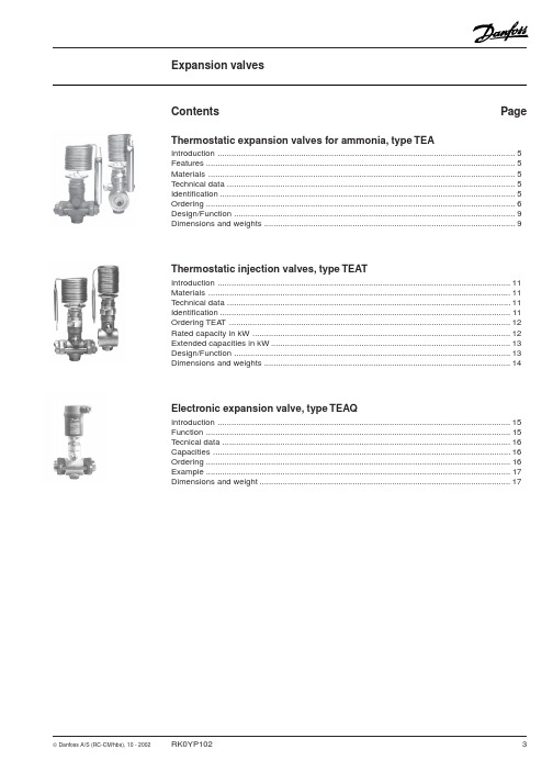
Introduction
Thermostatic expansion valves for ammonia type TEA
Thermostatic expansion valves regulate the injection of refrigerant liquid into evaporators. Injection is controlled by the refrigerant superheat.
Thermostatic injection valves, type TEAT
Introduction .............................................................................................................................. 11 Materials .................................................................................................................................. 11 Technical data .......................................................................................................................... 11 Identification ............................................................................................................................. 11 Ordering TEAT ......................................................................................................................... 12 Rated capacity in kW ............................................................................................................... 12 Extended capacities in kW ....................................................................................................... 13 Design/Function ....................................................................................................................... 13 Dimensions and weights .......................................................................................................... 14
ETS电子膨胀阀

温ŏ传感,
温ŏ传感,/ Pt 1000 ohm
AKS 11
Temp. Range
[℃]
Cable [m]
3.5
-50 +100
5.5
8.5
Code No.
084N0003 084N0006 084N0008
AKS 12
Temp. Range [℃]
-40 +80
Cable [m]
Quantity
• MOP 设ୱ • ࣯୧备य电౧
继电,输ෆ
• 报警
12 REFRIGERATION AND AIR CONDITIONING
丹佛斯控制器特点
ୢਨ
参数设,调试简单ࠇཥ
• ়ر参数ũ可过控,来设
13 REFRIGERATION AND AIR CONDITIONING
丹佛斯控制器特点
33
“
060G2101 060G2105 060G2049 060G2117
40
0 +80 060G2102 060G2106 060G2050 060G2118
55
“
060G2103 060G2107 060G2051 060G2119
Cable G 3/8 A
¼ Flare 060G2062
060G2065
ୢձ
2种过热ŏ控Ϸ܉ • ઞ适应过热ŏ/ඟخ稳态过热ŏ (ෆ厂设) • 负载ୱ义过热ŏ
ཥ业ʻ̩ඟ优ଝ过热ŏ控Ϸ܉
•• TThhrroouugghhSSHHsseeaarrcchhiningg,,rreeffeerreenncceeSSHH vvaalulueettoobbeelolowweerreeddttililllssuuccttioionntteemmpp.. hhaauunnttiningg
丹佛斯小型电子膨胀阀ETS6 技术资料英文
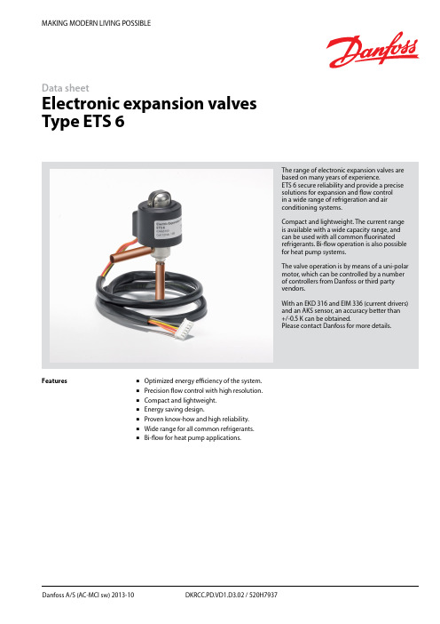
MAKING MODERN LIVING POSSIBLEDanfoss A/S (AC-MCI sw) 2013-10 DKRCC.PD.VD1.D3.02 / 520H7937Data sheetElectronic expansion valves Type ETS 6The range of electronic expansion valves are based on many years of experience.ETS 6 secure reliability and provide a precise solutions for ex p ansion and flow control in a wide range of refrigeration and air conditioning systems.Compact and lightweight. The current range is available with a wide capacity range, and can be used with all common fluorinated refrigerants. Bi-flow operation is also possible for heat pump systems.The valve operation is by means of a uni-polar motor, which can be controlled by a number of controllers from Danfoss or third party vendors.With an EKD 316 and EIM 336 (current drivers) and an AKS sensor, an accuracy better than +/-0.5 K can be obtained.Please contact Danfoss for more details.FeaturesOptimized energy efficiency of the system. Precision flow control with high resolution. Compact and lightweight. Energy saving design.Proven know-how and high reliability. Wide range for all common refrigerants. Bi-flow for heat pump applications.2DKRCC.PD.VD1.D3.02 / 520H7937Danfoss A/S (AC-MCI sw) 2013-10Data sheetElectronic Expansion Valves, type ETS 6Design/functionThe ETS 6 electronic expansion valves open and close to regulate refrigerant flow by means of a screw, whose rotating motion is transformed into linear motion. This occurs by the rotation of a magnet-needle valve assembly whichmoves when electrical signals are applied to the surrounding coil.Within the coil structure, there are different winding configurations, and the polarities arechanged by the electrical signals applied. By application of the appropriate combination of signals, in the form of pulses, the coil forces the rotor of the valve to move in a stepwise fashion.Application of multiple pulses will make the valve mechanism to move through a series of steps in the chosen direction, in order to set the valve with the required opening degree.CoilPermanent magnet motorNeedle valveValve bodyCross section diagram of ETS 6 series* Refers to refrigerant flow in cooling modeOutlet (A*)Inlet (B*)Technical dataFig. 1ApprovalsComplies with: EC PED 97/23/EC a3P3UL, RoHS and CQCRoHSData sheet Electronic Expansion Valves, type ETS 6Danfoss A/S (AC-MCI sw) 2013-10 DKRCC.PD.VD1.D3.02 / 520H79373Electrical wiringStepper motor switch sequenceThe illustration shows the JST XHP-6 connetor. The coil with JST XHP-5 is identical except that it does not have an unused pinCT=38°C, ET=5°C, SC=0°C, SH=0°C*Please contact Danfoss if higher maximum reverse pressure valve is required.1) Max. Reverse Pressure = Pressure as which the valve can still close tightly in reverse direction (from A to B see fig. 1).Valve ordering4 DKRCC.PD.VD1.D3.02 / 520H7937 Danfoss A/S (AC-MCI sw) 2013-10Data sheetElectronic Expansion Valves, type ETS 6For optimum performance, it is important to correct the evaporator capacity. In order toselect the correct size of ETS 6 you will need the following information:Refrigerant: HCFC or HFCEvaporator capacity Q e in kW or TR Evaporating temperature t e in °C or °F Condenser temperature t c in °C or °F Subcooling Δt sub in K or °F ExampleWhen selecting the valve it may be necessary to apply a correction factor to the actual evaporator capacity. This correction factor is required when system conditions are different than tableconditions. Selection also depends on having an acceptable pressure drop across the valve. In the selection table, the pressure drop in the liquid line is assumed to be zero. The following example illustrates correct selection of the valve.Refrigerant: R407CEvaporator capacity: Q e = 10 kW (2.84TR)Condensing temperature: t c = 40°C (104 °F) Evaporating temperature: t e = +10°C (50°F) Subcooling Δt sub = 10 KApplication exampleValve SelectionHeat pump components in typical system.1. Compressor.2. Controller.3. Four-way valve.4. Temperature sensor.5. Pressure transmitter.6. Cartridge pressure control.7. Evaporator.8. Condenser.9. Temperature sensor.10. Electronic expansion valve.11. Sight glass.12. Liquid line filter drier.Data sheetElectronic Expansion Valves, type ETS 6Danfoss A/S (AC-MCI sw) 2013-10 DKRCC.PD.VD1.D3.02 / 520H7937 5Step 1Determine the correction factor for subcooling Δt sub . From the correction factor table (see below) a subcooling of 10 K, R407C corresponds to a factor of 1.14.Correction factors for subcooling Δt sub .Step 2Corrected evaporator capacity isQ e (Corrected) = 10 kW/1.14 = 8.8 kW (2.5 TR)Step 3Select the appropriate capacity table, R407C, and choose the column for condensing temperature of t c = 40°C (104°F) and evaporating temperature of t e = 10°C (50°F) which will provide anequivalent or greater capacity of 8.8 kW (2.5 TR).ETS 6-18 provides 10.35 kW (2.94 TR), which is the proper selection for this example.Step 4Choose ETS 6-18:Single pack code no. 034G5026 I-pack code no. 034G5024Valve Selection (continued)Rated Capacity (kW)Correction factors for subcooling Δt subThe evaporator capacities used must be corrected if subcooling deviates from 0 K.The corrected capacity can be obtained bydividing the required evaporator capacity by the correction factor below. Selections can then bemade from the tables above.6 DKRCC.PD.VD1.D3.02 / 520H7937 Danfoss A/S (AC-MCI sw) 2013-10Data sheetElectronic Expansion Valves, type ETS 6Rated Capacity (kW)Rated Capacity (kW)Data sheetElectronic Expansion Valves, type ETS 6Danfoss A/S (AC-MCI sw) 2013-10 DKRCC.PD.VD1.D3.02 / 520H79377Rated Capacity (kW)Rated Capacity (kW)Data sheetElectronic Expansion Valves, type ETS 6Rated Capacity (kW)8 DKRCC.PD.VD1.D3.02 / 520H7937 Danfoss A/S (AC-MCI sw) 2013-10Data sheetElectronic Expansion Valves, type ETS 6Danfoss A/S (AC-MCI sw) 2013-10 DKRCC.PD.VD1.D3.02 / 520H79379Rated Capacity (TR)Rated Capacity (TR)10 DKRCC.PD.VD1.D3.02 / 520H7937 Danfoss A/S (AC-MCI sw) 2013-10Data sheetElectronic Expansion Valves, type ETS 6Rated Capacity (TR)Rated Capacity (TR)Data sheetElectronic Expansion Valves, type ETS 6Danfoss A/S (AC-MCI sw) 2013-10 DKRCC.PD.VD1.D3.02 / 520H793711Rated Capacity (TR)Rated Capacity (TR)Data sheet Electronic Expansion Valves, type ETS 6 Capacities, continuedConditionsR410 AT e: 5°CT c: 38°C Subcooling: 0°C Superheat: 0°C(B to A ref. drawing page 1)12 DKRCC.PD.VD1.D3.02 / 520H7937 Danfoss A/S (AC-MCI sw) 2013-10Data sheetElectronic Expansion Valves, type ETS 6Danfoss A/S (AC-MCI sw) 2013-10 DKRCC.PD.VD1.D3.02 / 520H7937 13DimensionsETS 6-10ETS 6-14ETS 6-25ETS 6-32ETS 6-40All dimensions in mmETS 6-18All dimensions in mmRelated Danfoss ProductsWeight: 0.16 kg (complete)。
丹佛斯-自动控制产品介绍

38
精选完整ppt课件
调节范围
39
精选完整ppt课件
ACB 插式压力控制器
40
精选完整ppt课件
ACB,即插式压力控制器
ACB 即插式压力控制器是一种小型圆盘式压力控 制器用于制冷和空调系统中。 ACB 型配有标准的 6 安培接触系统,可以自动 回复或手动回复. ACB强度高,可靠,紧凑,轻巧,防护等级高, 可以直接安装在制冷系统需要压力调节的地方.
另一种是组合式由导阀操纵的电磁阀(电磁主阀 PML)
30
精选完整ppt课件
PML电磁阀
31
精选完整ppt课件
32
精选完整ppt课件
VHV/STF 4通换向阀
33
精选完整ppt课件
34
精选完整ppt课件
电磁阀的选择:
1、它所适用的流体介质
2、基本的流动配置,例如,两通,三通,常开,常闭等
3、流体的温度和压降
MP54为固定压差设定器型,带有一个固定释放时间间隔的时间 延时继电器
MP55和MP55A为可调性压差器,而且有时间继电器盒不带时 间继电器两种类型
49
精选完整ppt课件
特点及技术参数
调节范围宽,可用于冷冻,冷藏和空气调节系统 适用于所有的常用氟化物制冷剂 接触压差小 允许电压波动 +10~-15% 最大工作压力 PB=170bar 温度补偿 时间继电器为温度补偿型 补偿范围:-
安装于制冷系统高压侧之间的旁通管路上, 高压侧直接注入到吸气管中
65
精选完整ppt课件
66
精选完整ppt课件
CPCE 能量调节阀
67
精选完整ppt课件
68
精选完整ppt课件
丹佛斯机械热力膨胀阀产品介绍

REFRIGERATION AND AIR CONDITIONING
11
REFRIGERATION AND AIR CONDITIONING
12
Orifice assembly
REFRIGERATION AND AIR CONDITIONING
13
REFRIGERATION AND AIR CONDITIONING
Presetting on present version
7
TD1 Application
Market segments: • Refrigerators and Freezers • Water heat pump units • Vending machines • Glass Door Merchandiser • Bottle Coolers • Beer Dispensers • Electronics/Cabinet Cooling • Drinking Water & Cooler Fountains • Compressed Air Driers • Frozen Beverage Machines • Mobile Refrigerator & Freezer • Wine Cellar • Cold Rooms • Ice Maker
➢MWP: 42,5bar R410A 34bar excl. R410A
➢capacity:0,17 to 4,5 TR ➢Refrigerant range:
N: -40 to +10℃ NM: -40 to -5℃ B: -60 to -25℃
REFRIGERATION AND AIR CONDITIONING
TC Series
电子膨胀阀控制系统原理安装调试丹弗斯

电子膨胀阀控制系统原理安装调试丹弗斯集团企业公司编码:(LL3698-KKI1269-TM2483-LUI12689-ITT289-电子膨胀阀控制系统原理,安装调试1,电子膨胀阀系统原理1.1系统组成电子膨胀阀阀体ETS控制器EKC312压力传感器AKS33温度传感器AKS111.2各个部件的作用电子膨胀阀,负责根据接受到的脉冲信号控制膨胀阀开度,保证适量的供液量和合适过热度。
压力传感器:负责检测蒸发压力,并将蒸发压力值转变成4-20mA的电流信号。
温度传感器:可以根据温度的不同电阻值也不同。
(温度和电阻值对照表参见附件1)。
控制器:控制器是该系统的核心器件,作用类似于人体大脑。
控制器可以接受压力传感器送来的4-20mA电流信号,和温度传感器的电阻值信号。
根据这些信号,通过内部的计算发出脉冲信号来控制电子膨胀阀的开度,保证系统供液量和过热度。
正常运转时,控制器显示系统的实际过热度。
1.3系统工作原理控制器采样压力传感器送来的4-20mA电流信号,和温度传感器的电阻值信号,计算出当前实际过热度;参考设定参数,计算出应当达到的要求过热度;根据实际过热度和要求过热度,结合控制器的参数设定,以一定的反映方式,来调节电子膨胀阀开度,使其尽量靠近要求过热度。
反复检测两个过热度之间的差异,逐步时事调整膨胀阀开度。
说明,在系统稳定的情况下尽量减小要求过热度,以提高系统效率。
2,电子膨胀阀系统调试2.1系统安装电子膨胀阀:安装之前必须参考丹佛斯电子膨胀阀的安装指南,每一个电子膨胀阀包装那都有一份安装指南。
注意4个电线的颜色和对应连接。
控制器:按右图连接对应电线,尤其注意电源符合要求(24V交流)。
压力传感器:按下图接线。
压力传感器接线必须牢固,压力接口最好在水平铜管的上方,以免杂质堵塞。
如果使用过渡铜管连接压力接口,过渡铜管的长度应当尽量短。
保证压力传感器固定牢固,以免运输震动损坏传感器。
温度传感器:温度传感器必须牢固的紧贴管壁,并用保温层可靠包裹,同时使用卡篐固定。
- 1、下载文档前请自行甄别文档内容的完整性,平台不提供额外的编辑、内容补充、找答案等附加服务。
- 2、"仅部分预览"的文档,不可在线预览部分如存在完整性等问题,可反馈申请退款(可完整预览的文档不适用该条件!)。
- 3、如文档侵犯您的权益,请联系客服反馈,我们会尽快为您处理(人工客服工作时间:9:00-18:30)。
MAKING MODERN LIVING POSSIBLETechnical brochureElectrically operated expansion valves, type AKV 10, AKV 15 and AKV 20HCFC and Non-flamable HFCThe valve requires no adjustment Wide regulation range Replaceable orifice assemblyBoth expansion valve and solenoid valve. Wide range of coils for d.c. and a.c.Features AKV are electrically operated expansion valves designed for refrigerating plant. The AKV valves can be used for HCFC and HFC, R744 refrigerants. The AKV valves are normally controlled by a con-troller from Danfoss’ range of ADAP- KOOL® con-trollers.The AKV valves are supplied as a component pro-gramme, as follows:Separate valveSeparate coil with terminal box or cableSpare parts in the form upper part, orifice and filterThe individual capacities are indicated with a number forming part of the type designation. The number represents the size of the orifice of the valve in question. A valve with orifice 3 will for example be designated AKV 10-3.The orifice assembly is replaceable.The AKV 10 valves covers a capacity range from 0.6 kW to 14 kW (R404A/R507) and are divided up into 7 capacity ranges.The AKV 15 valves cover a capacity range from 14 kW to 85 kW (R404A/R507) and are divided up into 4 capacity ranges.AKV 15 valves can be used for cold rooms.The AKV 20 valves cover a capacity range from 56 kW to 530 kW (R404A/R507) and are divided up into 5 capacity ranges.The AKV 20 can be used for water chiller units.Electrically operated expansion valves, type AKV 10, AKV 15 and AKV 20Technical dataRated capacity and OrderingCondensing temperature t c = 32°C Liquid temperature t l = 28°C Evaporating temperature t e =5°CFilter.On plants using AKV 15 or AKV 20 a filter must be mounted in front of AKV 15 and AKV 20.AKV 10 has built-in filter and ex-ternal filter is not necessary.DEMKO, Denmark SETI, FinlandSEV, SwitzerlandUL listed (separate code. nos.) CSA certified (separate code. nos.)ApprovalsElectrically operated expansion valves, type AKV 10, AKV 15 and AKV 20Filter: Contents:Code no. 068F054010 pcs. filters10 pcs. Al. gasketsUpper part: Contents: Code no. 068F05411 pc. armature ass.1 pc. armature tube 1 pc. Al. gasketGasket for upper part: Contents:Code no. 068F054925 pcs. Cu/Tn gasketsSpare parts AKV 10AKV 15AKV 20Filter: Contents:Code no. 068F054010 pcs. filters10 pcs. Al. gasketsUpper part: Contents:Code no. 068F50451 pc. armature ass.1 pc. armature tube 1 pc. Al. gasketGasket for upper part: Contents:Code no. 068F054925 pcs. Cu/Tn gasketsGasket set: Contents:Code no. 042H0160Complete gasket set for new and oldvalvesUpper part: Contents:Code no. 068F50451 pc. armature ass.1 pc. armature tube 1 pc. Al. gasketGasket for upper part: Contents:Code no. 068F054925 pcs. Cu/Tn gasketsOrificePistonGasket set:Contents:Code no. 068F526330 pcs. O-rings 10 pcs. Cu. gasket10 pcs. gasketPistonOrifice setElectrically operated expansion valves, type AKV 10, AKV 15 and AKV 20Electrically operated expansion valves, type AKV 10, AKV 15 and AKV 20CapacityThe evaporator capacity used must be corrected, if the subcooling deviates from 4 K.Use the actual correction factor indicated in the table.Multiply the evaporator capacity by the correc-tion factor to obtain the corrected capacity.Correction for subcoolingElectrically operated expansion valves, type AKV 10, AKV 15 and AKV 20Capacity(continued)The evaporator capacity used must be corrected, if the subcooling deviates from 4 K.Use the actual correction factor indicated in the table.Multiply the evaporator capacity by the correc-tion factor to obtain the corrected capacity.Correction for subcoolingElectrically operated expansion valves, type AKV 10, AKV 15 and AKV 20Capacity (continued)Correction for subcoolingThe evaporator capacity used must be corrected, if the subcooling deviates from 4 K.Use the actual correction factor indicated in the table.Multiply the evaporator capacity by the correc-tion factor to obtain the corrected capacity.Electrically operated expansion valves, type AKV 10, AKV 15 and AKV 20To obtain an expansion valve that will function correctly under different load conditions it is necessary to consider the following points when sizing the valve:These points must be dealt with in the following sequence:1) Evaporator capacity2) Pressure drop across the valve 3) Correction for subcooling4) Correction for evaporating temperature 5) Determination of valve size6) Correctly dimensioned liquid lineValve sizing1) Evaporator capacityThe evaporator capacity is found in the specifi-cations from the evaporator supplier.2) Pressure drop across the valveThe pressure drop across the valve directly determines the capacity and must therefore be considered.The pressure drop across the valve is normally calculated as the condensing pressure less the evaporating pressure and sundry other pressure drops in the liquid line, distributor, evaporator, etc.It is indicated in the following formula:∆p valve = p c – (p e + ∆p 1 + ∆p 3 + ∆p 4)∆p 3 pressure drop across the distributor system ∆p 4 pressure drop across the evaporatorNote!distributor system must be calculated on the basis of the valve’s max. capacity, as the valve operates with pulse-width modulation.Example of calculation of pressure drop across a valve:Refrigerant: R22Condensing temperature: 35°C (p c = 13.5 bar)Evaporating temperature: 0 - 6°C (p e = 4.1 bar)∆p 1 = 0.2 bar ∆p 3 = 0.8 bar ∆p 4 = 0.1 barThis will give you the following equation:∆p valve = p c – (p e + ∆p 1 + ∆p 3 + ∆p 4) = 13.5 – (4.1 + 0.2 + 0.8 + 0.1) = 8.3 bar The found value for “pressure drop across the valve” is used later in the section “Determination of valve size”.Electrically operated expansion valves, type AKV 10, AKV 15 and AKV 203) Correction for subcoolingThe evaporator capacity used must be cor-rected, if the subcooling deviates from 4 K. Use the actual correction factor indicated in the table.Multiply the evaporator capacity by the correc-tion factor to obtain the corrected capacity.Valve sizing (continued)The corrected capacity is used in the section “De-termination of valve size”.Example of corection:Refrigerant: R22Evaporator capacity Q e : 5 kW Subcooling: 10 KCorrection factor according to the table = 0.94Corrected capacity = 5 × 0.94 = 4.7 kW.Note: Too little subcooling may cause flash gas.4) Correction for evaporating temperature (t e ) To obtain a correctly dimensioned valve it is important that the application is considered. Depending on the application, the valve should have an overcapacity enabling it to cope with the extra amount of refrigeration needed during certain periods, e.g. during the defrost recovery process.The valve’s opening degree should therefore be between 50 and 75% when regulating. In this way it is ensured that the valve has a sufficiently wide regulation range, so that it can manage changed loads at or near the normal working point.Correction factors based on the evaporating tem-perature are indicated below:5) Determination of valve sizeWhen the valve size meeting the required ca-pacity is selected it is important to note that the capacity indications are the valve’s rated capacity, i.e. when the valve is 100% open.In this section we tell you how the valve’s size is determined.There are three factors that have an influence on the choice of the valve:- the pressure drop across the valve - the corrected capacity (correction for subcooling)- the corrected capacity for evaporating temperatureThe three factors have been described earlier in this section on dimensioning. When these three factors have been established, the selec-tion of the valve can be made:- First you multiply the “corrected capacity” by a value stated in the table.- Use the new value in the capacity table in com-bination with the pressure drop value.- Now select the valve size.Example of selection of valveUse as starting point the two earlier mentioned examples, where the following two values have been obtained:∆p valve = 8.3 bar Q e corrected = 4.7 kWThe valve should be used in a coldroom. Conse-quently, 1.25 should be selected as “correction factor for the evaporating temperature”.The dimensioned capacity will then be: 1.25 x 4.7 kW = 5.88 kW.Now select a valve size from one of the capacity tables.With the given values ∆p valve = 8.3 bar and a ca-pacity of 5.88 kW, select the valve size for AKV 10-5.This valve will have a capacity of approx. 7 kW.Electrically operated expansion valves, type AKV 10, AKV 15 and AKV 20Valve sizing(continued)6) Correctly dimensioned liquid lineTo obtain a correct supply of liquid to the AKVvalve, the liquid line to the individual AKV valvemust be correctly dimensioned.The liquid flow rate should not exceed 1 m/sec. This must be observed on account of the pressure drop in the liquid line (lack of subcooling) and pulsations in the liquid line.Dimensioning of the liquid line must be based on the capacity of the valve at the pressure drop with which it is operating (cf. capacity table), and not on the evaporator’s capacity.AKV 15AKV 20AKV 10DKRCC.PD.VA1.A5.02 / 520H658811Electrically operated expansion valves, type AKV 10, AKV 15 and AKV 20Design1. I nlet2. Outlet3. Orifice4. Filter5. Valve seat6. Armature7. Copper gasket 8. Coil9. DIN plug 12. O-ring1. I nlet2. Outlet3. Orifice4. Piston assembly 7. Coil8. Armature 9. Pilot orifice 10. Filter 11. Cover12. Valve body 13. Spring14. Orifice assembly1. I nlet2. Outlet3. Orifice4. Valve seat5. Filter6. Pilot orifice7. O-ring8. Coil9. Terminal boxAKV 15DKRCC.PD.VA1.A5.02 / 520H658812Electrically operated expansion valves, type AKV 10, AKV 15 and AKV 20The valve capacity is regulated by means of pulse-width modulation. Within a period of six seconds a voltage signal from the controller will be transmitted to and removed from the valve coil. This makes the valve open and close for the flow of refrigerant.The relation between this opening and closing time indicates the actual capacity. If there is an intense need for refrigeration, the valve will remain open for almost all six seconds of the period. If the re-quired amount of refrigeration is modest, the valve will only stay open during a fraction of the period. The amount of refrigeration needed is de-termined by the controller.When no refrigeration is required, the valve will remain closed and thus function as a solenoid valve.FunctionDimensions and weightsAKV 10 solderAKV 20© Danfoss A/S (AC-MCI sw), 2012.07 DKRCC.PD.VA1.A5.02 / 520H658813Dimensions and weights(continued)。