深圳安耐特EnaelSM协议调试手册
深圳特安可燃气体报警器技术手册

第八分册技术手册内部文件不得复制第 7 章深圳特安可燃气体报警器深圳特安可燃气体报警器包括探测器和控制器两部分,本公司推荐使用的为探测器部分,控制器部分则为可选项,有特殊要求的用户可以选择。
我们推荐使用的两种探测器型号为JB-QT-TON90A和 ES2000T两种。
一.摘要JB-QT-TON90A可燃气体探测器产品特点测量精度高:传感器采用进口气体敏感元件,具有精度高、选择好等特点。
总线制连接:总线传输(四总线)方便接线,降低用户安装成本。
数字信号总线输出:数字信号总线传输提高系统的抗干扰能力。
隔爆型防爆:可用于工厂条件的1、 2 区危险场所。
电源:工业标准DC24V供电。
安装方便:传感器探头结构采用外部插拔式,若现场更换探头,只需旋开防护罩,即可进行更换;内部机芯设计采用组件形式,组件之间采用插接式连接,现场维修只需更换组件即可完成。
ES2000T可燃气体探测器产品特点测量精度高:传感器采用进口气体敏感元件,具有精度高、选择好等特点。
多种线制连接: ES2000T(两三线制)气体变送器是工业用可燃/ 有毒气体安全检测仪器。
多种信号:可输出4~ 20mA标准电流信号,便与DCS、 PLC等工业自动化系统连接。
隔爆型防爆:可用于工厂条件的1、 2 区危险场所。
安装方便:专业设计的安装支架,仪器现场安装方便、快捷。
维修方便:传感探头结构采用外部插拔式,若现场更换探头,只需旋开防护罩,即可进行更换;内部机芯设计采用组件形式,组件之间采用插接式联接,现场维修只需更换组件即可完成。
第八分册技术手册内部文件不得复制二.技术规格JB-QT-TON90A可燃气体探测器技术指标检测原理:催化燃烧式;检测气体:天然气、液化石油气、煤气、烷类、醇、酮、苯、汽油等ⅡC级 T6 组可燃气体;测量范围: 0~100%LEL;精度:± 5%FS;信号输出:标准4~ 20mA电流输出;防爆方式:隔爆型;防爆标志: ExdⅡCT6;防爆连接螺纹:G3/4 管螺纹;工作电压: AC220V/50Hz;最大功耗:小于等于 5.5W/ 路温度范围: - 40℃~ +70℃相对湿度: 20%~ 95%RHES2000T可燃气体探测器技术指标检测原理:催化燃烧式,电化学式检测气体: C2H2, H2S,CO, CO2, CL2, NH3等可燃气体;测量范围: 0~100%LEL,0~ 1000ppm;报警设定:低限25%LEL(可在 2%至 25%之间任意设定),高限50%LEL;精度:± 3%FS;信号输出:标准4~ 20mA电流输出;防爆方式:隔爆型;防爆标志: ExdⅡCT6防爆连接螺纹:G3/4 管螺纹工作电压: DC24V最大功耗:小于等于 5.5W/ 路温度范围: - 40℃~ +70℃相对湿度: 20%~ 95%RH规格及适用气体第八分册技术手册QJ/FcA0330 - 2006内部文件不得复制基本规格所测气体常备量程检测方式接线方式ES2000T-C可燃气体100%LEL催化燃烧式三线制ES2000T-H2氢气100%LEL催化燃烧式三线制ES2000T-H2氢气5%VOL电化学式两线制ES2000T-NH3氨气100%LEL催化燃烧式三线制ES2000T-NH3氨气200ppm电化学式两线制ES2000T-CO一氧化碳200ppm电化学式两线制ES2000T-H2S硫化氢50ppm电化学式两线制ES2000T-O2氧气25%VOL电化学式两线制ES2000T-Cl2氯气10ppm电化学式两线制三.仪表尺寸及安装指导说明1、JB-QT-TON90A可燃气体探测器总结构图安装固定1、先将安装支架固定在安装立柱上(如安装点没有合适的立柱选用直径20m-80mm的铁管作为安装立柱固定在安装点)。
SM ECM-SMART 模块使用手册说明书

4ECM-SMART模块使用手册产品描述SM ECM-SMAR电化学气体传感器模块是利用电化学原理,对环境中的CO、H2S、NO2等有毒有害气体浓度进行检测。
模块以盛密科技四系列三电极电化学传感器为敏感元件(传感器具体技术参数详见数据手册),在采样电路控制下实现气体浓度的检测,具有良好的稳定性、选择性。
本模块与接收终端采用四线制连接方式,将气体浓度信号通过UART总线输出,方便用户使用。
本品具有零偏压断电自动短接PIN脚功能,对于零偏压传感器,上电30分钟后即可稳定使用;对于带偏压的传感器,建议用户上电24小时以上再进行使用。
图1盛密4系列电化学传感器俯视图侧视图仰视图图2模块尺寸及引脚定义Vin GND TXD RXD 电源输入正极电源输入负极串口发送串口接收技术指标产品型号SM ECM-SMART检测气体CO、H2S、NO2等有毒有害气体检测原理电化学量程详见数据手册分辨率详见数据手册测量误差<±5%FS工作电压(3.5~5.5)VDC工作电流≤2mA@+5.0VDC输出方式UART(+3.3V TTL电平)工作温度-20℃~+50℃工作湿度0%~90%RH(无冷凝)工作压力1±0.1标准大气压存储温度-20℃~+60℃外形尺寸Φ24.2x26.8mm重量10克通讯设置波特率9600bps数据位8位停止位1位校验位无通讯命令本模块采用串口(TXD/RXD)进行数据传输,传输方式采用问答式。
数据传输均为16进制(HEX)格式。
无特殊说明时,应答回复时间小于100ms(特殊情况请参考具体指令说明),当前命令回复前无法响应其他指令。
1.终端读取模块信息命令示例:AA0F01C580EEByte1--AA:命令起始符;Byte2--0F:信息读取命令;Byte3--01:模块地址(默认为0x01);Byte4--C5:CRC16(Modbus);Byte5--80:CRC16(Modbus);Byte6--EE:命令结束符;注:本命令中对Byte2、Byte3进行CRC16(Modbus)校验校验方法参照附录1模块应答(向终端发送信息数据)示例:AA0F010F001400050002000102C599EEByte1--AA:命令起始符;Byte2--0F:信息读取命令;Byte3--01:模块地址;Byte4--0F:传感器类型;Byte5/6--00/14:模块测量范围(16进制)Byte7/8--00/05:标定气体浓度(16进制)Byte9/10--00/02:高报警点(16进制)Byte11/12--00/01:低报警点(16进制)Byte13--02:传感器读数单位(%LEL:0x00;%VOL:0x01;PPM:0x02;PPB:0X03;无:0x04)Byte14--C5:CRC16(Modbus);Byte15--99:CRC16(Modbus);Byte16--EE:命令结束符;注:本命令中对Byte2~Byte13进行CRC16(Modbus)校验校验方法参照附录1附表:传感器类型代码(十进制)00无01无02CO03O204H205CH406无07CO208O309H2S10SO211NH312无13ETO14HCL15PH316无17HCN18无19HF20无21NO22NO223NOX 24CLO225无26无27无28无29无30无31THT32C2H233C2H434CH2O35无36无37无38无39C2H3CL40无41CH3SH例:AA0F010F001400050002000102C599EE(十六进制0F=十进制15,即得到该传感器为PH3传感器)2.终端发送浓度数据读取命令示例:AA0101C1E0EEByte1--AA:命令起始符;Byte2--01:数据读取命令;Byte3--01:模块地址;Byte4--C1:CRC16(Modbus);Byte5--E0:CRC16(Modbus);Byte6--EE:命令结束符;注:本命令中对Byte2、Byte3进行CRC16(Modbus)校验校验方法参照附录1模块应答(向终端发送浓度数据)示例:AA01018000000015CA EEByte1--AA:命令起始符;Byte2--01:数据读取命令;Byte3--01:模块地址;Byte4--80:数据符号位(0x80:负;0x00:正);Byte5/6--00/00:数据(ppm)整数部分(0~65535);Byte7--00:数据(ppm)小数部分(0.00~0.99);Byte8--15:CRC16(Modbus);Byte9--CA:CRC16(Modbus);Byte10--EE:命令结束符;注:本命令中对Byte2~Byte7进行CRC16(Modbus)校验校验方法参照附录13.终端发送模块校零命令示例:AA0201C110EEByte1--AA:命令起始符;Byte2--02:校零命令;Byte3--01:模块地址;Byte4--C1:CRC16(Modbus);Byte5--10:CRC16(Modbus);Byte6—EE:命令结束符;注:1)本命令中对Byte2、Byte3进行CRC16(Modbus)校验;校验方法参照附录12)校零期间LED以1秒/次的频率闪烁,持续时间30秒。
安奈特三层交换机配置手册

安奈特三层交换机配置手册AlliedWare Plus TM OSHow T o |IntroductionThis How T o Note introduces a number of commonly-used management features of the AlliedWare Plus TM operating system (OS), the next generation operating system for Allied T elesis, Inc’s high performance layer 3 managed switches.ContentsIntroduction (1)Contents (1)Related How T o Notes (2)Which products and software version does it apply to? (2)Important differences between the AlliedWare OS and the AlliedWare Plus OS (3)How to log in (4)How to get command help (5)How to work with command modes (9)How to see the current configuration (14)Default settings (15)The default configuration script (16)How to change the password (17)How to set a management IP address (17)How to save and boot from the current configuration (18)How to save to the default configuration file (18)How to create and use a new configuration file (18)How to return to the factory defaults (20)How to see systeminformation ....................................................................................................... .. 21Get Started With The AlliedWare Plus TM Operating System IntroductionHow to set system parameters (23)How to change the telnet session timeout (23)How to name the switch (23)How to display a text banner at login (24)How to set the time and date (25)How to show current settings (25)How to set the time and date (25)How to set the timezone (26)How to configure summer-time (26)How to add and remove users (28)Pre-encrypted passwords (29)How to undo settings (30)How to use the no parameter (30)How to use the default parameter (30)How to work with files (31)How to list files (31)How to display the contents of configuration and text files (33)How to navigate through the file system (34)How to copy files (36)How to use the editor (38)How to upgrade the firmware (39)Appendix: Commands available in each mode (40)User Exec mode (40)Privileged Exec mode (41)Global Configuration mode (42)Related How T o NotesY ou may also find the following AlliedWare Plus OS How T o Notes useful:z How To Configure Basic Switching Functionalityz How T o Configure EPSR (Ethernet Protection Switching Ring) to Protect a Ring from Loops Which products and software version does it apply to? This How T o Note applies to the following Allied T elesis switches, running AlliedWare Plus software version 5.2.1 or later:z SwitchBlade x908z x900 seriesImportant differences between the AlliedWare OS and the AlliedWare Plus OS Important differences between the AlliedWare OS and the AlliedWare Plus OSThe most noticeable differences between the AlliedWare Plus and AlliedWare OSes are:z The command mode hierarchy. With the AlliedWare Plus OS, you go into an appropriate mode before entering configuration or monitoring commands.For details of the modes, see "How to work with command modes"on page9.z The style of the commands. Because you go into a configuration mode, the AlliedWare Plus OS already knows that you are entering a configuration command.Therefore, you do not have to begin commands with keywords like create. This means that many commands are shorter.z How the switch identifies values in commands. The AlliedWare Plus OS either has parameter keywords immediately followed by a space and their value (for an example, see "How to add and remove users"on page28), or simply has a series ofspace-separated values (for an example, see "How to set the time and date"on page25). For manycommands, you must enter the values in the correct order. The ? help makes this easy by prompting you for values one at a time.z How to undo an action or remove a setting. Mostly you remove settings by re-entering the configuration command with the keyword no before it. See "How to undo settings"on page30.z The things the command line warns you about. In the AlliedWare Plus OS: z If you try to create an object (such as a user, trigger etc) and an object with that name already exists, the switch overwrites the original object. It does not warn you before doing so.The file copying commands are an example of an exception to this—the switch asks if you want to overwrite the file.z Y ou only get a message telling you that an operation failed, not if it succeeds. If the switch does not display an error message, you can assume the command wassuccessful.z Port numbering. In the AlliedWare Plus OS, switch ports are named port x.y.z (e.g.port1.0.1), where:z the first number (x) is the stack ID numberz the second number (y) is the module number (0 for base ports and higher numbers for XEMs)z the third number (z) is the port number.z Associating VLANs with switch ports. In the AlliedWare Plus OS, VLANs are configured as an attribute of switch ports. T o associate a VLAN with a port, you enter Interface Configuration mode for the port, not for the VLAN. For details and examples,see the following AlliedWare Plus How T o Note: How To Configure Basic SwitchingFunctionality.z Flash compaction. In the AlliedWare Plus OS, Flash compaction takes up to a minute.The command line is unresponsive during this time. Do not power cycle the switch during Flash compaction.How to log in How to log in1.Set the console baud rateSet the baud rate of your terminal emulator to 115200.For bootloader version 1.0.8 and earlier, this is the switch’s default value. Y ou can use a bootloader menu option to change it, but the first time you access the switch, you must use 115200.Note that in bootloader version 1.0.9, the default baud rate will change to 9600.2.Login with manager/friendLike in AlliedWare, the defaults are:username: managerpassword: friendThe switch logs you into User Exec mode. From User Exec mode, you can perform high-level diagnostics (some show commands, ping, traceroute etc), start sessions (T elnet, SSH), and change mode.How to get command helpThe following kinds of command help are available:zlists of valid parameters with brief descriptions (the ? key)z completion of keywords (the T ab key)z error messages for incomplete or incorrect syntaxT o get syntax help, type ? after:z the prompt, to list all commands available in themode you are inz one or more parameters, to list parameters thatcan come next in the partial commandzone or more letters of a parameter, to listmatching parameters Example T o see which commands are available in User Exec mode, enter “?” at the User Exec mode command prompt:awplus>?This results in the following output:X View a list of valid parameters Tip:The AlliedWare Plus OS only displays one screenful of text at a time, with the prompt “--More--” at the end of each screenful. Press the space bar to display the next screenful or the Q key to return to the command prompt.Exec commands:clear Reset functionsdisable Turn off privileged mode commandecho Echo a stringenable Turn on privileged mode commandexit End current mode and down to previous modehelp Description of the interactive help systemlogout Exit from the EXECmstat Show statistics after multiple multicast traceroutesmtrace Trace multicast path from source to destinationping Send echo messagesquit Exit current mode and down to previous moderemote-command Remote stack member command executionshow Show running system informationssh Open an SSH connectiontelnet Open a telnet connectionterminal Set terminal line parameters traceroute Trace route to destinationExample T o see which show commands that start with “i” are available in User Exec mode, enter “?”after show i:awplus>show i?This results in the following output:interface Interface informationip Internet Protocol (IP)ipv6 Internet Protocol version 6 (IPv6)Example T o use the ? help to work out the syntax for the clock timezone command (page26), enter the following sequence of commands:awplus(config)#clock ?summer-time Manage summer-timetimezone Set clock timezoneawplus(config)#clock timezone ?TIMEZONE Timezone name, up to 6 charactersawplus(config)#clock timezone NZST ?minus negative offset (West of Greenwich)plus positive offset (East of Greenwich)awplus(config)#clock timezone NZST plus ?OFFSET Time zone offset to UTC in HH or HH:MM formatawplus(config)#clock timezone NZST plus 12The above example demonstrates that the ? help only indicates what you can type next. Forcommands that have a series of parameters, like clock timezone, the ? help does not makethe number of parameters obvious.X Complete keywordsT o complete keywords, type T ab after part of the command.If only one keyword matches the partial command, the AlliedWare Plus OS fills in thatkeyword. If multiple keywords match, it lists them.Example T o use T ab completion to enter the command show ip dhcp server summary, enter the following commands. We have included “” to show where to type the T ab key—it is not displayed on screen.awplus>show ipas-path-access-list bgp community-listdhcp dhcp-relay domain-listdomain-name extcommunity-list filterforwarding igmp interfaceirdp mroute mvifname-server nat ospfpim protocols riproute rpfawplus>show ip ddhcp dhcp-relay domain-list domain-nameawplus>show ip dhcpbinding pool serverawplus>show ip dhcp server sstatistics summaryawplus>show ip dhcp server summaryX View command messagesThe switch displays the following generic error messages about command input:% Incomplete command—this message indicates that the command requires more parameters. Use the ? help to find outwhat other parameters are available.awplus(config)#interfaceinterface% Incomplete command.% Invalid input detected at '^' marker—this indicates that the switch could not process the command you entered. The switch also prints the command and marks the first invalid character by putting a '^' under it. Note that you may get this error if you enter a command in the wrong mode, as the following output shows.awplus#interface port1.0.1interface port1.0.1^% Invalid input detected at '^' marker.% Unrecognized command—when you try to use ? help and get this message, it indicates that the switch can not provide help on the command because it does not recognise it. This means the command does not exist, or that you have entered it in the wrong mode, as the following output shows.awplus#interface ?% Unrecognized commandThe AlliedWare Plus OS does not tell you when commands are successful. If it does not display an error message, you can assume the command was successful.How to work with command modesThe following figure shows the command mode hierarchy and the commands to use to move to lower-level modes.X User Exec modeUser Exec mode is the mode you log into on the switch.It lets you perform high-level diagnostics (show commands, ping, traceroute etc), start sessions (T elnet, SSH), and change mode.For a list of commands available in this mode, see "User Exec mode"on page40.The default User Exec mode prompt is awplus>.T o change from User Exec to Privileged Exec mode, enter thecommand:awplus>enable Privileged Exec mode is the main mode for monitoring—forexample, running show commands and debugging. FromPrivileged Exec mode, you can do all the commands from User Exec mode plus many systemcommands.For a list of commands available in this mode, see "Privileged Exec mode"on page 41.The default Privileged Exec mode prompt is awplus#.T o change from Privileged Exec to Global Configuration mode,enter the command:awplus>configure terminal From Global Configuration mode, you can configure mostaspects of the switch.For a list of commands available in this mode, see "Global Configuration mode"on page 42.The default Global Configuration mode prompt is awplus(config)#.X Privileged Exec modeX Global Configuration mode Tip:en is a short-cut forenable Tip:conf t is a short-cut forconfigure terminalA number of features are configured by entering a lower-level mode from GlobalConfiguration mode. The following table lists these features.Some protocols have commands in both Global Configuration mode and lower-levelconfiguration modes. For example, to configure MSTP , you use:zGlobal Configuration mode to select MSTP as the spanning tree mode zMST mode to create instances and specify other MSTP settings z Interface Configuration mode to associate the instances with the appropriate ports.X Lower-level configuration modesModeWhat it configures Command Default prompt InterfaceSwitch ports, VLANs, the management Eth port.interface name awplus(config-if)#Class map QoS classes, which isolate and name specifictraffic flows (classes) from all other traffic.(first enable QoS globally with mls qos enable)class-map name awplus(config-cmap)#EPSR Ethernet Protection Switching Ring, a loopprotection mechanism with extremely fastconvergence times.epsr configuration awplus(config-epsr)#Line Console port settings or virtual terminalsettings for telnet.line console 0line vty number awplus(config-line)#Ping poll Ping polling, which checks whether specifieddevices are reachable or not.ping-poll number awplus(config-ping-poll)#Policy map QoS policies, a collection of user-defined QoS classes and the default class.(first enable QoS globally with mls qos enable)policy-map nameawplus(config-pmap)#Policy map classThe QoS actions to take on a class-map, andwhich class-maps to associate with a QoSpolicy.This mode is a sub-mode of Policy map mode.(in Policy map mode)class name awplus(config-pmap-c)#Route map Route maps, which select routes to include or exclude from the switch’s routing table and/or route advertisements.route-map name deny|permit entry-numberawplus(config-route-map)#Router Routing using BGP , IP , IPv6, OSPF , RIP , or VRRP .router protocolother-parametersawplus(config-router)#MST Multiple Spanning T ree Protocol.spanning-tree mst configuration awplus(config-mst)#T rigger T riggers, which run configuration scripts inresponse to events.trigger number awplus(config-trigger)#VLAN databaseVLANs.vlan database awplus(config-vlan)#X Returning to higher-level modesThe following figure shows the commands to use to move from a lower-level mode to ahigher-level mode.Examples T o go from Interface Configuration to Global Configuration mode:awplus(config-if)#exitawplus(config)#T o go from Interface Configuration to Privileged Exec:awplus(config-if)#endawplus#T o go from Privileged Exec to User Exec:awplus#disableawplus>X Entering Privileged Exec commands when in a configuration modeWhen you are configuring the switch, you are likely to want to enter show commands toconfirm the configuration. This can mean you change often between configuration modes andPrivileged Exec mode.However, you can run Privileged Exec commands without changing mode, by using thecommand:doHowever, you cannot use the ? help to find out command syntax when using the docommand.Example T o display information about the IP interfaces when in Global Configuration mode, enter the command:awplus(config)#do show ip int briefThis results in the following output:Interface IP-Address Status Protocoleth0 172.28.8.200 admin up runningvlan1 unassigned admin up running...How to see the current configurationHow to see the current configurationThe current configuration is called the running-config. T o see it,enter the following command in either Privileged Exec mode or any configuration mode:awplus#show running-config T o see only part of the current configuration, enter thecommand:awplus#show running-config |includeThis displays only the lines that contain word .T o start the display at a particular place, enter the command: awplus#show running-config |beginThis searches the running-config for the first instance of word and begins the display with thatline.Tip:show running-config works in all modesexcept User Exec mode.Default settingsWhen the switch first starts up with the AlliedWare Plus OS, it applies default settings and copies these defaults dynamically into its running-config.These default settings mean that the AlliedWare Plus OS:z encrypts passwords, such as user passwordsz records log message priority in log messagesz turns on jumbo frame support for all portsz turns on the telnet server so that you can telnet to the switchz enables the switch to look up domain names (but for domain name lookups to work, you have to configure a DNS server)z turns off L3 multicast packet switching in the swi tch’s hardware. This prevents L3 multicasts from flooding the switch’s CPU in its default state as an L2 switchz sets the maximum number of ECMP routes to 8z turns on RSTP on all ports. Note that the ports are not set to be edge portsz sets all the switch ports to access mode. This means they are untagged ports, suitable for connecting to hostsz creates VLAN 1 and adds all the switch ports to itz allows logins on the serial console portz allows logins on VTY sessions (for telnet etc)z has switching enabled, so layer 2 traffic is forwarded appropriately without further configurationz allocates all the routing table memory space to IPv4 routes (instead of IPv6 routes)z has ports set to autonegotiate their speed and duplex modez has copper ports set to auto MDI/MDI-X modez has all switch ports attached to VLAN 1The default configuration scriptMost of the above default settings are in the form of commands, which the switch copies toits running-config when it first boots up.The switch stores a copy of the default configuration commands in the file default.cfg anduses that file as its default start-up file.For more information about start-up files, see "How to save and boot from the currentconfiguration"on page18.The following figure shows the contents of the default file.Contents of default file Description!An empty comment line (comments begin with an !). service password-encryption!Forces passwords in the script to be encrypted.log record-priority Records log message priority.username manager privilege 15 password 8$1$bJoVec4D$JwOJGPr7YqoExA0GVasdE0Specifies the password for the manager userservice telnet!T urns on the telnet server.ip domain-lookup!Allows domain name lookups.no ip multicast-routing !T urns off L3 multicast packet switching in the switch hardware.maximum-paths 8Sets maximum number of ECMP routes. spanning-tree mode rstp!T urns on RSTP.interface eth0 !A heading for any configuration settings for the management eth0 port. There are no eth0 settings.interface port1.0.1-1.0.24switchportswitchport mode access!Sets each switch port to access mode.interface vlan1!Creates VLAN 1.line con 0 A heading for any configuration settings for the console port.There are no console port settings.line vty 0 32 !end A heading for any configuration settings for VTY sessions. There are no VTY session settings.How to change the password How to change the password T o change the password for the manager account, enter Global Configuration mode and enter the following command:awplus(config)#username manager passwordThe password can contain any printable character and is case sensitive.How to set a management IP addressThis section describes how to set an IP address on the eth0 management port.1.If desired, check the current configurationAfter logging in, enter Privileged Exec mode by using the command:awplus>enableThen check the current configuration by using one of the following commands:awplus#show ip interface eth0 briefThis results in the following output:Interface IP-Address Status Protocoleth0 172.28.8.200 admin up runningawplus#show running-config interface eth0This results in the following output:!interface eth0ip address 172.28.8.200/16!2.Enter Interface Configuration mode for the eth0 interfaceEnter Global Configuration mode and enter the command: awplus(config)#interface eth03.Enter the IP address and maskEnter the command:awplus(config-if)#ip addressFor example, to set the address to 172.28.8.210/16, enter the command:awplus(config-if)#ip address 172.28.8.210/16How to save and boot from the currentconfigurationThis section tells you how to save your configuration and run the saved configuration whenthe switch starts up.Y ou can either:z save the configuration to the switch’s default configuration file (called “default.cfg”). Bydefault, the switch uses that file at start-up.zcreate a new configuration file and set the switch to use the new configuration file atstart-up.How to save to the default configuration fileEnter Privileged Exec mode and enter the command:awplus#copy running-config startup-configThe parameter startup-config is a short-cut for the current boot configuration file, whichwill be the default configuration file unless you have changed it, as described in the nextsection.How to create and use a new configuration fileEnter Privileged Exec mode and enter the command:awplus#copy running-config .cfgExample T o save the current configuration in a file called example.cfg, enter the commandawplus#copy running-config example.cfgT o run the new file’s configuration when the switch starts up, enter Global Configurationmode and enter the command:awplus(config)#boot config-file .cfgExample T o run the commands in example.cfg on startup, enter the command awplus(config)#boot config-file example.cfg1.Copy the current configuration to a new file2.Set the switch to use the new file at startup3.Display the new settingsT o see the files that the switch uses at startup, enter Privileged Exec mode and enter the command:awplus#show bootThe output looks like this:Boot configuration--------------------------------------------------------------------Current software : r1-5.2.1.relCurrent boot image : flash:/r1-5.2.1.relBackup boot image : Not setDefault boot config: flash:/.configs/default.cfgCurrent boot config: flash:/example.cfg (file exists)4.Continue updating the file when you change the configurationWhen you next want to save the current configuration, enter Privileged Exec mode and enter the command:awplus#copy running-config startup-configThe parameter startup-config is a short-cut for the current boot configuration file.。
SENTRONIC AG 安全自动化解决方案说明书
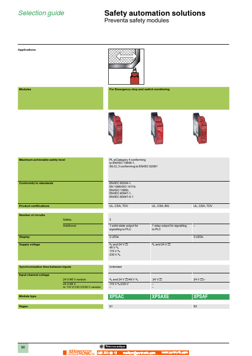
Selection guideSafety automation solutionsPreventa safety modules056 222 38 18SEN TRONIC AGO perating principle, characteristics Safety automation solutions Preventa safety modules types XPSAC, XPSAXEFor Emergency stop and switch monitoringOperating principleSafety modules XPSAC and XPSAXE are used for monitoring Emergency stop circuits conforming to standardsEN/ISO 13850 and EN/IEC 60204-1 and also meet the safety requirements for the electrical monitoring ofswitches in protection devices conforming to standard EN 1088/ISO 14119. They provide protection for both themachine operator and the machine by immediately stopping the dangerous movement on receipt of a stopinstruction from the operator, or on detection of a fault in the safety circuit itself.To aid diagnostics, the modules have LEDs which provide information on the monitoring circuit status.The XPSAC module has 3 safety outputs and a solid-state output for signalling to the PLC.The XPSAXE module has 3 safety outputs and a relay output for signalling to the PLC.Characteristics (continued), r eferencesSafety automation solutionsPreventa safety modules types XPSAC,XPSAXEFor Emergency stop and switch monitoringEmergency stop and switch monitoringclamp terminals Terminal block integrated in module48 V a XPSAC13210.210115 V aXPSAC34210.210230 V a XPSAC37210.210Captive screw clamp terminals Terminal block removable from module3 1 solid-state a and 24 V c XPSAC5121P 0.16048 V aXPSAC1321P0.210115 V a XPSAC3421P 0.210230 V a XPSAC3721P 0.2101 relaya and 24 V c XPSAXE5120P0.229Spring terminals Terminal block removable from module3 1 relay a and 24 V c XPSAXE5120C 0.229XPSAXE5120P XPSAXE5120CXPSAC pppp PXPSAC ppppO perating principle, characteristics Safety automation solutions Preventa safety modules type XPSAF For Emergency stop and switch monitoringOperating principleSafety modules XPSAF meet the requirements of Performance Level PL e/Category 4conforming to standard EN/ISO 13849-1.They are used for:b Monitoring Emergency stop circuits conforming to standards EN/ISO 13850 andEN/IEC 60204-1.b Electrical monitoring of switches activated by protection devices conformingto standard EN 1088.Housed in a compact enclosure, the modules have 3 safety outputs.Preventa safety modules XPSAF pppp P incorporate removable terminal blocks, thusoptimising machine maintenance.To aid diagnostics, the modules have 3 LEDs on the front face which provideinformation on the monitoring circuit status.The Start button monitoring function is configurable depending on the wiring.R eferences, connections Safety automation solutions Preventa safety modules type XPSAF For Emergency stop and switch monitoringReferencesDescription Type of terminalblock connection Number of safetycircuitsSupply Reference WeightkgSafety modules forEmergency stop and switchmonitoringIntegrated in module3a and 24 V c XPSAF5130 0.250Removable from module 3a and 24 V c XPSAF5130P0.250XPSAF5130Operating principle, characteristics Safety automation solutions Preventa safety modules type XPSAKFor Emergency stop, switch, sensing mat/edges or safety light curtain monitoringOperating principleSafety modules XPSAK meet the requirements of Performance Level PL e/Category 4conforming to standard EN/ISO 13849-1.They are used for:b Monitoring Emergency stop circuits conforming to standards EN/ISO 13850 andEN 60204-1.b Electrical monitoring of switches activated by protection devices, with optionalselection of synchronisation time between signals.b Monitoring 4-wire sensing mats or edges.b Monitoring type 4 light curtains conforming to EN/IEC 61496-1 which havesolid-state safety outputs with test function (light curtains XUSL).Housed in a compact enclosure, the modules have 3 safety outputs, a relay signallingoutput and 4 solid-state signalling outputs for signalling to the process PLC.Preventa safety modules XPSAK pppp P incorporate removable terminal blocks, thusoptimising machine maintenance.To aid diagnostics, the modules have 4 LEDs on the front face which provideinformation on the monitoring circuit status.The Start button monitoring function is configurable depending on the wiring.Characteristics, references Safety automation solutions Preventa safety modules type XPSAKFor Emergency stop, switch, sensing mat/edges or safety light curtain monitoringEmergency stop, switch,sensing mat/edges or safetylight curtain monitoringin module24 V c110 V a24 V cXPSAK361144 0.400120 V a24 V cXPSAK351144 0.400230 V a24 V cXPSAK371144 0.400Removable from module 3 1 / 424 V a24 V cXPSAK311144P0.30048 V a XPSAK331144P0.300110 V a24 V cXPSAK361144P 0.400120 V a24 V cXPSAK351144P 0.400230 V a24 V cXPSAK371144P 0.400XPSAK3p1144O perating principle, characteristics Safety automation solutions Preventa safety modules type XPSARFor Emergency stop, switch or safety light curtain monitoringOperating principleSafety modules XPSAR meet the requirements of Performance Level PL e/Category 4 conforming to standard EN/ISO 13849-1 and are designed for thefollowing safety applications:b Monitoring Emergency stop circuits conforming to EN/ISO 13850 andEN/IEC 60204-1.b Electrical monitoring of switches activated by protection devices conformingto standard EN 1088/ISO 14119.b Monitoring type 4 light curtains conforming to EN/IEC 61496-1 that havesolid-state safety outputs with test function (light curtains XUSL).In addition to 7 safety outputs, modules XPSAR incorporate 2 relay signallingoutputs and 4 solid-state signalling outputs for signalling to the process PLC.Safety modules XPSAR p p p p p p P incorporate removable terminal blocks, thusoptimising machine maintenance.To aid diagnostics, the modules have 4 LEDs on the front face which provideinformation on the monitoring circuit status.C haracteristics, references Safety automation solutions Preventa safety modules type XPSARFor Emergency stop, switch or safety light curtain monitoringEmergency stop, switchor safety light curtainmonitoringin module24 c115 a24 cXPSAR3511440.400230 a24 cXPSAR3711440.400Removablefrom module7 2 / 4 24 a24 cXPSAR311144P0.300115 a24 cXPSAR351144P0.400230 a24 cXPSAR371144P0.400 XPSAR3p1144O perating principle, c haracteristics Safety automation solutions Preventa safety modules type XPSVNE For zero speed detectionOperating principlePreventa safety modules XPSVNE for zero speed detection are used to detect thestop condition of electric motors. Their most common applications include: providingthe unlock signal for electrically interlocked sliding or removable machine guards,controlling rotation direction signals for reversing motors and engaging lockingbrakes after a motor has come to a standstill.As electric motors run down, a remanent voltage is produced in the windings of themotor due to residual magnetism. This voltage is proportional to the speed of themotor and, therefore, decreases as the motor comes to a standstill.This remanent voltage is measured in a redundant manner so as to detect the stopcondition of the motor. The cabling between the motor windings and the inputs of theXPSVNE module is also monitored to prevent a cabling breakage or fault being seenas a stopped motor.A transformer should not be used to connect the motor to terminals Z1, Z2 and Z3since there is no monitoring of the connection with the motor winding via theresistance monitoring.Modules XPSVNE are suitable for detecting the stop condition of all types of ACor DC motor driven machines which, when the motor runs down, produce a remanentvoltage in the windings due to residual magnetism. These machines can be controlledby electronic devices, such as variable speed drives or DC injection brakes.The input fi lters for standard XPSVNE modules are designed for a frequencyof up to 60 Hz.For motors operating at a frequency higher than 60 Hz, which therefore produce a highfrequency remanent voltage, special modules XPSVNE pppp HS should be used.Modules XPSVNE have 2 potentiometers mounted on the front face of the modulewhich allow independent adjustment of the switching threshold for each input circuit.This allows adjustment for different types of motors and application requirements.To aid diagnostics, modules XPSVNE have 4 LEDs and 2 solid-state outputs to provideinformation on the status of the zero speed detection circuit.C haracteristics, references Safety automation solutions Preventa safety modules type XPSVNEFor zero speed detectioncontact has not been used for switching high power loads (possible contamination or wearof the gold layer on the contact tips).ReferencesDescription Number ofsafety circuits Solid-stateoutputs forPLCSupply Frequency ofmotor powersupplyReference WeightkgSafety modules for zerospeed detection2224 V c y 60 Hz XPSVNE1142P0.500> 60 Hz XPSVNE1142HSP0.500115 V a y 60 Hz XPSVNE3442P0.600> 60 Hz XPSVNE3442HSP0.600230 V a y 60 Hz XPSVNE3742P0.600> 60 Hz XPSVNE3742HSP0.600 XPSVNE pppppO perating principle, characteristics Safety automation solutions Preventa safety modules types XPSDMB, XPSDMEFor coded magnetic switch monitoringOperating principleSafety modules XPSDMB and XPSDME are specifi cally designed for monitoringcoded magnetic safety switches. They incorporate two safety outputs and twosolid-state outputs for signalling to the process PLC. Conforming to PerformanceLevel PL e/Category 4 conforming to EN/ISO 13849-1, modules XPSDMB canmonitor two independent sensors and modules XPSDME can monitor up to sixindependent sensors.To monitor a higher number of magnetic switches using these safety modules,the magnetic switches can be connected in series parallel, while meeting therequirements of Performance Level PL d/Category 3 conforming to standardEN/ISO 13849-1.Safety modules XPSDM ppppp P incorporate removable terminal blocks, thusoptimising machine maintenance.To aid diagnostics, the modules have LEDs on the front face which provideR eferences Safety automation solutionsPreventa safety modules types XPSDMB,XPSDMEFor coded magnetic switch monitoringmonitoring 2 codedmagnetic switchesin moduleSafety module for monitoring 6 coded magnetic switches Integratedin module2 NO224 c XPSDME11320.300Safety module for monitoring 2 coded magnetic switches Removablefrom module2 NO 2 24 c XPSDMB1132P 0.250Safety module for monitoring 6 coded magnetic switches Removablefrom module2 NO224 c XPSDME1132P 0.300XPSDMB1132XPSDME1132。
安奈特说明
AT-S39 v3.3.1 AT-S39 v3.3.1 AT-S39 v3.3.1 AT-S39 v3.3.1 AT-S39 v3.3.1 AT-S39 v3.3.1 AT-S39 v3.3.1
安奈特产品说明 AT-8024M AT-8026FC AT-8026T AT-8088/MT AT-8088/SC AT-8124 AT-8124XL (V2) AT-8216FXL/SC AT-8224XL AT-8324 AT-8324SX AT-8326GB AT-8350GB AT-8400 AT-8403 Fan Tray for AT-8400 AT-8411 8-port (RJ-45) Line Card AT-8412 4-port (MT-RJ) Line Card AT-8412 4-port (SC) Line Card AT-8413 2-port (GBIC/RJ-45) Line Card AT-8414 4-port (SC) Line Card AT-8414 4-port (ST) Line Card AT-9006SX/SC AT-9006T AT-9410GB 4. L2+ 交换机 AT-8516F/SC AT-8524M AT-8524POE AT-8550GB AT-8550SP AT-8724XL AT-8724XL-DC AT-8748XL AT-8748XL-DC AT-9408LC/SP (new!) AT-9424T/GB AT-9424T/SP 5. L3 交换机 AT-8624POE (new!) AT-8624T/2M AT-8824 AT-8848 Rapier 16F/MT Rapier 16F/SC
安耐特电源(SM32J)协议调测交维手册
安耐特电源(SM32J)协议调测交维手册协议调测交维手册归档格式说明:1、文档名称:厂家+设备类型+设备型号+协议调测交维手册2、黑色字体为模板固定内容,红色字体和照片为实际填写内容3、需要增加内容或特殊说明时,可以在相应的位置增加,并以红色字体格式。
4、在调测交维手册中附上协议压缩包。
1、设备信息厂家名称:安耐特设备名称:开关电源设备型号:【设备照片】2、监控屏信息监控屏型号:SM32J(注意,该监控模块面板无型号丝印,需要参看下图确定)软件版本:无监控屏操作密码:888【监控屏照片】3、接口信息通信方式:RS485波特率:9600,n,8,1地址:1接口板拔码或跳线:无接线端子:RJ45(水晶头插口)连接方式:采集器(COM口凤凰端子) <──────> 设备端(水晶接头)D+ <──────> RS485+ (2)D- <──────> RS485- (3) 【接口板照片】电源监控板RS485端口信号定义对应水晶头线序应为如下:RS485需连接的线:RS485+、RS485-4、协议信息适用协议编码:PenatelSM32E6-001 2 3 4 5 6 7 8RS485+ RS485-5、铁塔交维测试(1)防雷器告警测试:拔出一个防雷器(2)整流模块故障告警测试:拔出一个整流模块,出现模块通信中断告警(3)停电告警测试:断开交流输入开关防雷器、整流模块、市电空开位置见下图箭头指向。
注意:先做防雷和模块故障告警,最后做断电告警,在FSU页面上看到告警后,要把以上告警恢复。
Eaton Moeller NZM 电缆保护设备说明说明书
Eaton 259543Eaton Moeller series NZM - Molded Case Circuit Breaker.Undervoltage release, 480-525VAC, +2early N/O, HIVGeneral specificationsEaton Moeller series NZM release259543NZM1-XUHIV480-525AC401508259543237 mm66 mm32 mm0.056 kgIECUL/CSA RoHS conform UL (File No. E140305)CSA (File No. 22086)UL listedCSA (Class No. 1437-01)UL489UL (Category Control Number DIHS) CSA-C22.2 No. 5-09CE markingIEC60947CSA certifiedProduct Name Catalog Number Model Code EANProduct Length/Depth Product Height Product Width Product Weight Compliances CertificationsIs the panel builder's responsibility. The specifications for the switchgear must be observed.480 VMeets the product standard's requirements.10 msIs the panel builder's responsibility. The specifications for the switchgear must be observed.Does not apply, since the entire switchgear needs to be evaluated.1.5 VAMeets the product standard's requirements.0 VTwo early-make auxiliary contacts0.8 W525 VIs the panel builder's responsibility.15 msUndervoltage release with 2 early-make auxiliary contacts, e.g., for early-make connection of undervoltage release in main switch applications, as well as for interlock and load shedding circuits. For use with emergency-stop devices in connection with an emergency-stop button. When the under-voltage trip is switched eaton-feerum-the-whole-grain-solution-success-story-en-us.pdf eaton-digital-nzm-brochure-br013003en-en-us.pdfeaton-digital-nzm-catalog-ca013003en-en-us.pdfDA-DC-03_NZM1eaton-circuit-breaker-release-nzm-mccb-dimensions.epseaton-circuit-breaker-undervoltage-nzm-mccb-3d-drawing-004.epsM1-XUHIV480-525ACIL01203002ZThe new digital NZM RangeIntroduction of the new digital circuit breaker NZMDA-CS-nzm1_xuDA-CD-nzm1_xueaton-nzm-technical-information-sheet10.11 Short-circuit ratingRated control supply voltage (Us) at AC, 50 Hz - min 10.4 Clearances and creepage distancesMinimum command time - min10.12 Electromagnetic compatibility10.2.5 LiftingPick-up power consumption at AC (undervoltage release) 10.2.3.1 Verification of thermal stability of enclosures Rated control supply voltage (Us) at DC - minFitted with:Pick-up power consumption at DC (undervoltage release) Rated control supply voltage (Us) at AC, 50 Hz - max 10.8 Connections for external conductorsMinimum command time - maxSpecial features BrochuresCatalogs Certification reports DrawingseCAD model Installation instructions Installation videos mCAD model Technical data sheetsoff, accidental contact with the circuit breaker’s primary contacts is prevented when switched on. Early make of auxiliary contacts on switching on and off (manual operation): approx. 20 ms Undervoltage releases cannot be installed simultaneously with NZM...-XHIV... early-make auxiliary contact or NZM...-XA... shunt release.Rated control supply voltage (Us) at DC - max0 V10.9.3 Impulse withstand voltageIs the panel builder's responsibility.Rated control supply voltage480 - 525 V 50/60 Hz10.6 Incorporation of switching devices and componentsDoes not apply, since the entire switchgear needs to be evaluated.10.5 Protection against electric shockDoes not apply, since the entire switchgear needs to be evaluated.Used withNZM1(-4), N(S)1(-4)Electric connection typeScrew connection10.13 Mechanical functionThe device meets the requirements, provided the information in the instruction leaflet (IL) is observed.10.2.6 Mechanical impactDoes not apply, since the entire switchgear needs to be evaluated.10.9.4 Testing of enclosures made of insulating materialIs the panel builder's responsibility.Number of contacts (normally closed contacts)10.3 Degree of protection of assembliesDoes not apply, since the entire switchgear needs to be evaluated.Voltage typeACDrop-out voltage of undervoltage release AC/DC - min0.35 x UsFrameNZM1Reaction time19 msSuitable forOff-load switchVoltage tolerance - min.85Rated control voltage (relay contacts)525 V AC480 V ACPower consumption1.5 VA (sealing AC)0.8 W (sealing DC)10.2.3.2 Verification of resistance of insulating materials to normal heatMeets the product standard's requirements.Drop-out voltage of undervoltage release AC/DC - max0.7 x Us10.2.3.3 Resist. of insul. mat. to abnormal heat/fire by internal elect. effectsMeets the product standard's requirements.Connection typeWith terminal block on the left-hand switch side10.9.2 Power-frequency electric strengthIs the panel builder's responsibility.Voltage tolerance - max1.1Undelayed short-circuit release - min0 ARated control supply voltage (Us) at AC, 60 Hz - min480 V10.7 Internal electrical circuits and connectionsIs the panel builder's responsibility.Terminal capacity (solid/flexible conductor)0.75 mm² - 2.5 mm² (2x) for undervoltage releases, off-delayed with ferrule18 - 14 AWG (1x) at shunt release0.75 mm² - 2.5 mm² (1x) for undervoltage releases, off-delayedEaton Corporation plc Eaton House30 Pembroke Road Dublin 4, Ireland © 2023 Eaton. All Rights Reserved. Eaton is a registered trademark.All other trademarks areproperty of their respectiveowners./socialmediawith ferrule18 - 14 AWG (1x) for undervoltage releases, off-delayed 18 - 14 AWG (2x) at shunt release18 - 14 AWG (2x) for undervoltage releases, off-delayed 0.75 mm² - 2.5 mm² (1x) at shunt release with ferrule 0.75 mm² - 2.5 mm² (2x) at shunt release with ferrule The panel builder is responsible for the temperature rise calculation. Eaton will provide heat dissipation data for the devices.Accessory Undervoltage release Undervoltage release with early-make auxiliary contact Meets the product standard's requirements.Meets the product standard's requirements.Meets the product standard's requirements.525 V20 A10.10 Temperature riseType10.2.2 Corrosion resistance10.2.4 Resistance to ultra-violet (UV) radiation 10.2.7 InscriptionsRated control supply voltage (Us) at AC, 60 Hz - max Number of contacts (normally open contacts)Undelayed short-circuit release - max Number of contacts (change-over contacts)。
深圳威华特 GAC LSM672 负荷分配模块 说明书
GAC LSM672负荷分配模块说明书LSM672说明LSM672负荷分配模块与其它专用组件一起装在发电机组控制屏内,该单元安装在不防碍冷却空气自然流通的地方,该单元有三个大负载的电阻,每个电阻消耗的功率高达6.25瓦。
接线电线连接见接线图。
电线的大小取决于分配模块接线端可能有的最大电流,端子T~12的电流可高达5安,其余端子小于50毫安(继电器触头除外,该处电流高达10安)端子N是“wye”组合发电机组的三相电压的中性连接点。
端字1~6接三相输入电压,根据发电机的电压,选择其中三个适合的端子,见说明书第2页。
警告:端子N和1~6有高压,操作(运转)时端子盖必须盖好!端子7~12接来自5安培变压器的三相输入电压。
仪表板(操纵板)交流器(CT)的伏安足够大,可进行串联连接。
负荷分配模块的交流器(CT)的负载为每相6.25VA,这是增加控制屏设备和交流器线路的负载额。
注意,一般交流器接到端子8、10、12时要经总工程师批准。
端子13和14是并车电缆连接端子,能把所有负载分配模块连在一起,必须注意它们的极性,如果这些电缆长度超过1米,则必须屏蔽,且屏蔽要在端子23处接地。
所用的继电器接触器必须适合最低电流值,小于1毫安(干接触时)。
端子15是负荷分配模块的输出端接到调速器的端子,如果连接电缆长度超过1米,则必须屏蔽,且屏蔽在端子23处接地。
端子16为正向功率复位(FORWARD POWER RESET)端子,把一个常开的按钮开关接到一个位于调速器上的+10伏的直流电源,当开关接零时,会使正向功率继电器自动复位到断开状态(OFF)。
把端子16接到电池负极可打开监测器。
正向功率监测器有程序控制开关点通到端子16。
在端子16与电池负极(端子23)之间连接一个1兆欧的电阻,可把原100%开(ON)40%关(OFF)的设定转换到85%开(ON)和5%关(OFF)的设定。
若要更多的程序设定请咨询GAC公司获取帮助。
Sensata 1 SC20-ALM 循环电流保护隔离电流放大器安装和操作指南说明书
SC20-ALMLOOP POWERED ISOLATING TRIP AMPLIFIERSafe Installation and Operation GuideCAUTION:This equipment is designed for possible connection to mains voltages (110V ac relay version) and must be used in accordance with this guide. If it is not, the safety protection provided by the equipment may be impaired.This equipment relies on double/reinforced insulation for safety and does not require a protective earth.Whilst every effort has been taken to ensure the accuracy of this document, we accept no responsibility for damage, injury, loss or expense resulting from errors or omissions, and reserve the right of amendment without notice. This document may not be reproduced in any way without the prior writtenpermission of the company.AUG 2022CONTENTS3 INTRODUCTION Page 15ANDINSPECTION Page UNPACKING23 WIRING CONNECTIONS ANDINSTALLATION Page 56 CONNECTIONS Page3.13.2 NOTES ON PROCESS INPUTS ANDOUTPUTS Page 63.37 INSTALLATION Page7 4OPERATION Page 5ELECTRICAL AND ENVIRONMENTAL8 SPECIFICATION Page5.1 POWER SUPPLY AND INSTALLATION8 CATEGORY Page5.2 ENVIRONMENTAL CONDITIONS Page 85.3 COMPLIANCE WITH EUROPEANCOMMISSION DIRECTIVES Page 81 INTRODUCTIONThis unit is intended to accept a 4-20mA current signal and provide a single pole normally open solid state relay contact output.An internal switch is used to select contact closure either above or below a set point which can be adjusted by a 20 turn front panel potentiometer and measured with a voltmeter.The power for the device is derived from the 4-20mA input loop.IMPORTANT Two different relay output options exist on the SC20-ALM:a) NB24V ac/dc @ 300mAVoltages above 100V peak will destroy the relay. The use of freewheel/clamp diodes across the coils of external relays and other inductive loads is recommended.b)110/115V ac @ 130mANB The 110V rated output is internally protected against over voltages up to 500V and no external clamp devices will generally be necessary. This relay type will not work with dc loads.4-20mA LOOP INPUTBLOCK DIAGRAM: 24V ac/dc RELAY VERSION4-20mA LOOP INPUTMAINS SAFETY ISOLATION (115V ac only, not 230V ac)2 UNPACKING AND INSPECTIONPlease inspect the instrument carefully for signs of shipping damage. The unit is packaged to givemaximum protection but we cannot guarantee that mishandling will not have damaged the instrument. In the case of this unlikely event: i)Do not use the instrument - physical damage may have compromised the safety insulation.ii)Please contact your supplier immediately and retain the packaging for subsequent inspection.Assuming the unit is undamaged please check the side label as follows:On one side of the enclosure you will find the serial number label, example of which is shown below:Please check that all the parameters are correct, especially, the Relay Rating.3 WIRING CONNECTIONS AND INSTALLATIONOn the front panel label you will find the connection details for the 4-20 mA loop input and relay contacts.Please study this carefully to ensure that the unit will be wired correctly. In particular please note the following; especially in the case of the 110V ac relay option:This symbol indicates that the unit is of Class IIconstruction - i.e. it provides double insulationbetween relay contacts and 4-20mA input wiringinside the enclosure. It is up to the installer topreserve this level of insulation outside the unit.This symbol means CAUTION! refer to this guide.It is recommended that bootlace ferrules are used on all wiring terminations. In any case the maximum terminal torque of 0.4Nm must not be exceeded. If it is the resulting damage to the terminal blocks and internal connections could compromise the integrity of the safety insulation. If in doubt get asmaller screwdriver.3.1 CONNECTIONSIN- 4-20mAInput -veIN+ 4-20mA Input +veOUT-Relay Output -ve OUT+Relay Output +ve The conductor of the 4-20mA loop which is normally at a more -ve potential.The conductor of the 4-20mA loop which is normally at a more +ve potential.Relay output contacts. Polarity is unimportant.Relay output contacts. Polarity is unimportant.3.2 NOTES ON PROCESS INPUTS AND OUTPUTSa)Operational CAUTION!The input is protected to a current of 30mA. The input will be damagedby application of any voltage source which is not limited to or fixed atless than 30 mA.See Section 1 of this guide for comments regarding the protection of therelay output.b)Safety The input circuit is classed as Separated Extra Low Voltage (SELV). Thismeans that it must not be externally connected to voltages exceeding 30V ac or60V dc, nor does it generate voltages above these limits internally.For the 110/115V ac relay version the output circuit is classed as hazardous liveand must be treated accordingly.3.3 INSTALLATION (and removal)4 The 20-ALM unit clips directly onto ‘Top Hat’ (TS35) symmetrical DIN rail or TS32 asymmetricalG-rail. Mounting orientation is not important. Ensure ambient temperature is below 55o C.NOTE: Good airflow around the unit will maximize reliability.The use of bootlace ferrules is recommended on wiring terminations.Do not exceed terminal torque rating of 0.4 Nm - Use an appropriate screwdriver.This unit can be removed from the DIN rail by gently levering the protrusion on the DIN rail clip up from the top of the rail (assuming unit is mounted vertically and upright) with a small screwdriver and lifting the top away from the DIN rail.OPERATIONThe 20-ALM unit has the following front panel components:(i)ALM LED(ii)Set PotentiometerThis will be lit when the relay output contacts are closed(i.e. in the ‘ALARM’ condition)This is a 20 turn device and adjusts the set point frombelow 4mA (full counter-clockwise) to above 20mA (fullclockwise). The set point can be monitored on the ‘SET’terminals.iii)SET Terminals+and -A voltage of 0.4 - 2.0V corresponds to 4-20mA span. The relay set-up is indicated on the serial number label as follows:R > SP means the relay will close above set pointR < SP means the relay will close below set pointTo change the relay action, gently lever off the side of the unit with the serial number label on it: Switch button closest to DIN rail clip: R > SPSwitch button furthest from DIN rail clip: R < SPWARNINGAlways isolate output voltage before opening unit.5 ELECTRICAL AND ENVIRONMENTAL SPECIFICATION 5.1 POWER SUPPLY AND INSTALLATION CATEGORY:Installation Category (according to IEC 664): II*(applies to 110/115V ac relay version only)Pollution Degree(according to EN61010-1 1993):2Relay voltage(stated on serial n o label):24V ac/dc nominal or 115V ac nominal Power consumption: Loopsupply=**************** Equipment Class(according to IEC 536):IIExternal fusing requirement (minimum): Not required*If it is required to employ units in installation category III, please contact the factory.5.2 ENVIRONMENTAL CONDITIONS(units are for indoor use):Operating altitude: Sea level to 2000mOperating temperature: 0 to 55o CStorage temperature: -40 to +70 o COperating/storage humidity 0 to 90% RHIf it is required to exceed any of these parameters, please contact the factory.5.3 COMPLIANCE WITH EUROPEAN COMMISSION DIRECTIVES:The SC20-ALM units comply with the following directives:EMC BSEN61326LVDStandardEN61010-1。
协议调试手册
协议调试手册(XXX设备)前人栽树,后人乘凉,请完整填写调试手册,谢谢艾默生网络能源(西安)有限公司版权所有,保留一切权利。
版权所有,侵权必究。
Copyright (C) 1998 by Emerson Network Power Co. Ltd.All rights reserved.一、引言1.协议适用的设备名称、型号、监控模块型号、系列号、协议版本号:协议适用:×××设备名称:×××设备型号:×××监控模块型号:×××2.产品描述i.代理商或厂家名称、联系人、电话:(请尽量说明清楚)代理商或厂家名称:×××联系人:×××联系人电话:×××ii.同类设备有哪些型号、监控模块有哪些型号:(此信息请尽量详细说明,最好写明如何区分等。
)1、2、3二、程序名说明1.动态库名:×××.dll2.SO库名:×××.SO3.模板库名:×××.mdb4.供应商测试程序:×××三、接口信息1.设备勘察信息:i.设备描述:(包括:监控模块照片、接口板照片、照片说明、接口位置、形状等信息。
)必须有ii.特别说明:(请用文字说明)a.判断有无接口板方法:无/有(如果有,请说明)b.是否需要另外购买:无/有(如果有,请说明)c.购买部件:无/有(如果有,请说明)d.串口接入能力说明:无/有(如果有,请说明)2.通信方式:i.有哪些通信方式(RS232/422/485),常用通信格式:(有特殊情况请一定说明)通信方式:RSXXX/ RSXXX/ RSXXX(9600,N,8,1/ 1200,E,8,1)常用通信格式:RSXXX(XXXX,X,X,X)ii.接口板设置和跳线:(有无通讯方式、波特率、地址设置和简要操作、操作密码等,写出设置步骤。
- 1、下载文档前请自行甄别文档内容的完整性,平台不提供额外的编辑、内容补充、找答案等附加服务。
- 2、"仅部分预览"的文档,不可在线预览部分如存在完整性等问题,可反馈申请退款(可完整预览的文档不适用该条件!)。
- 3、如文档侵犯您的权益,请联系客服反馈,我们会尽快为您处理(人工客服工作时间:9:00-18:30)。
编号:_______________本资料为word版本,可以直接编辑和打印,感谢您的下载
深圳安耐特EnaelSM协议调试手册
甲方:___________________
乙方:___________________
日期:___________________
协议调试手册
(安奈特电源)
版权所有,保留一切权利。
版权所有,侵权必究。
Copyright (C)1997 by ZTE Co. Ltd..
All rights reserved.
设备说明
设备名称:安奈特电源
设备型号:
监控模块型号:SM21
设备接口描述
图片资料:(尽可能提供设备和接口图片,不同型号设备存在差别)
通讯接口板说明:(如何判断有无接口板、接口板外观描述)
接口定义:(接口类型、定义)
RS232电平、DB9针、2接收、3发送、5地、
接口参数:(波特率、数据位、校验位、停止位)
RS232电平:波特率19200、数据位8位、无校验、起始/停止位1位监控模块操作及接口参数设置:(操作步骤、拨码设置等)
其他:(特殊说明)
调试方法
PcuDebug 名称:pcudebug.exe
测试技巧及注意事项:(通讯是否存在时限要求、是否存在控制条件等)
通道表(包括物理通道和逻辑通道)
---AI 通道---
[交流屏数据]
AI通道36 (双字节1)=交流电压A
AI通道37 (双字节2)=交流电压B
AI通道38 (双字节3)=交流电压C
AI通道39 (双字节7)=交流电流A
AI通道40 (双字节8)=交流电流B。