海林柯螺杆泵产品样本
G型螺杆泵样本
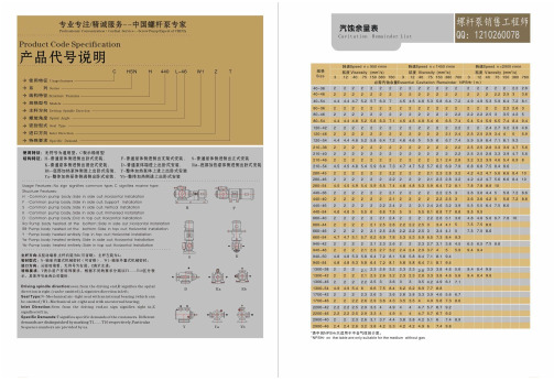
注;1、设计时以20℃的清水为介质其粘度υ=1mm2/S; 2、对于不同粘度及磨损特性的介质应选择不同的运转速度(见选泵指南)上表所列转速为参考转速; 3、输出流量的变化规律同转速及压差有关。
4
外形安装图
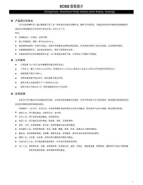
SCGG 型泵外形安装图及其尺寸表
ShangChuan, Shanchuan Pump Industry,water flowing ceasingly
和各种浓度的纸浆,短纤维浆料等的输送。
1
结构图
SCGG 型泵结构图、材料表及工作原理与结构说明
ShangChuan, Shanchuan Pump Industry,water flowing ceasingly
1
2
3
4
5
6
7
8
9
10
11
12
17
16
15
14
13
1 出 料腔
10 轴 承座
2 拉杆
11 轴 承盖
SCGG70-1 15kW
SCGG85-1 18.5kW
0.2
0
0
2.5
8
12
20
30
45
65
Q ( m 3/ h)
注:当转速改变时,流量Q随之而改变,但压力P保持不变(即曲线向右平移)。
3
SCGG 型泵性能参数表
ShangChuan, Shanchuan Pump Industry,water flowing ceasingly
联轴 器 HT2 00
填 料座
HT200 1Cr18 Ni9Ti
联 节轴
1 Cr18 Ni9Ti
螺杆套
无缝 钢管
填料
三螺杆泵产品样本(申贝泵业)
320
185
190
340
395
210
435
255
490
236
9
3GBW45,3G45 型 卧式泵外形及安装尺寸
三螺杆泵样本资料
外形安装尺寸(mm)
泵规格 机座号
AD
L
L1
L2
B
B1
B2
H
Y90L
155
345
430
680
Y100L 180
390
355
315
315
205
415
705
45x4-36 Y112M 190
410
Y132S
485
45x3-46
210
485
800
380
340
340
217
Y132M
525
45x2-52
Y160M
610
255
580
925
430
300
390
245
Y160L
655
10
3GFBW45,3GF45 型 法兰式泵外形及安装尺寸
三螺杆泵样本资料
泵规 机座
外形安装尺寸(mm)
格
号
AD L L1 L2 L3 L4 L5 L6 B B1 B2 H D1 D2 D3 D4 D5 D6
3、绷得吸入管路系统设计时应满足泵的吸入条件,即:
其中:H:泵吸入高度(m).
H=Hs-v²/2g-h
Hs:泵吸上真空高度(m).
v:泵的吸入口流速(m/s).
g:重力加速度(m/s²).
h:泵吸入管道中液力损失之和(m).
由上式可知,泵的吸入高度与泵的吸上真空高度、泵的入口流速和泵吸入端管路长短、弯
HSNH660-46三螺杆泵样本_黄山铁人泵业_SN系列三螺杆泵样本
泵型号转速r/min出口压力MPa运动粘度(mm2/s)3 12 40 75 380 760流量I/min轴功率Kw流量I/min轴功率Kw流量I/min轴功率Kw流量I/min轴功率Kw流量I/min轴功率Kw流量I/min轴功率KwSN 40-389500.5 16.5 0.24 18.2 0.34 19.1 0.34 19.5 0.37 20 0.46 20 0.551 13.3 0.49 16.5 0.5 18 0.5 18.5 0.53 19.5 0.63 19.7 0.731.5 10.5 0.59 14.8 0.67 17 0.68 18 0.71 19.1 0.8 19.4 0.892 13.2 0.85 16.2 0.85 17.2 0.88 18.6 0.88 19 1.072.5 15.1 1.02 16.6 1.05 18.5 1.15 18.7 1.25 14500.5 27.6 0.41 29.3 0.41 29.9 0.41 30.6 0.48 31.1 0.7 31.2 0.931 24.5 0.67 27.6 0.68 28.6 0.68 29.9 0.78 30.7 0.97 30.9 1.21.5 21.6 0.93 26 0.94 27.4 0.94 29.2 1.01 30.4 1.23 30.7 1.52 24.5 1.2 26.3 1.2 28.6 1.27 30.1 1.49 30.4 1.812.5 25.2 1.46 28 1.53 29.8 1.75 30.2 1.99 29000.5 58.8 1.23 60 1.23 61.6 1.23 62.1 1.52 62.4 2.4 62.2 3.271 55.8 1.74 58 1.74 60.6 1.74 61.3 2.03 62 2.92 62 3.721.5 532.26 55.8 2.26 59.5 2.26 60.5 2.57 61.63.42 61.84.322 50 2.82 54 2.82 58.8 2.82 59.9 3.08 61.2 3.96 61.6 4.832.5 52.13.33 57.5 3.33 59.4 3.62 60.84.5 61.45.47SN 40-469500.5 21.8 0.3 24.1 0.39 25.5 0.39 26.1 0.42 26.5 0.52 26.7 0.621 17.5 0.61 21.8 0.62 24 0.62 25 0.65 26 0.75 26.4 0.841.5 13.4 0.85 19.1 0.85 22.8 0.85 24.1 0.88 25.5 0.98 26 1.082 17.2 1.08 21.6 1.08 23.2 1.11 25 1.21 25.6 1.322.5 21 1.9 22.4 1.34 24.5 1.44 25.2 1.54 14500.5 36.7 0.55 38.7 0.55 40.1 0.55 40.6 0.58 41.2 0.8 41.3 1.11 32.6 0.95 36 0.95 38.8 0.95 39.7 0.93 40.7 1.16 41 1.441.5 28.5 1.31 33.9 1.31 37.6 1.31 38.8 1.27 40.2 1.5 40.7 1.822 31.8 1.64 36.4 1.64 38 1.64 40.1 1.84 40.4 2.142.5 35.3 1.99 37.2 1.99 39.6 2.2 40.2 2.51 29000.5 78.7 1.4 81 1.4 82.1 1.4 82.7 1.68 83.2 2.56 83.4 3.441 74.4 2.1 78.5 2.1 80.8 2.1 81.7 2.38 82.7 3.26 83.1 4.141.5 70.52.8 76.3 2.8 79.6 2.81 813.01 82.2 3.96 82.94.842 66.8 3.5 74.2 3.5 78.4 3.51 80.2 3.78 81.8 4.65 82.6 5.542.5 72.1 5.21 77.3 4.2 79.3 4.48 81.4 5.37 82.4 6.24SN 80-36 9500.5 31 0.5 33.6 0.5 35.2 0.5 36 0.54 36.8 0.67 37 0.791 26 0.81 31 0.81 34 0.82 34.8 0.85 36.2 0.98 36.3 1.112.5 29.5 1.76 31.2 1.82 33.6 1.93 34.5 2.041450 0.5 51 0.69 53.7 0.69 55.2 0.69 56.1 0.79 56.9 1.09 57 1.391 46 1.17 51 1.17 53.7 1.17 55 1.28 56.1 1.6 56.8 1.941.5 41.4 1.67 48.3 1.67 52.2 1.67 53.8 1.76 55.5 2.14 56 2.422 45.7 2.14 49.8 2.14 53 2.22 55.1 2.62 55 2.9 2.5 49.5 2.62 52 2.74 54.5 3.1 54.7 3.322900 0.5 109 1.8 110 1.8 113 1.8 114 2.16 114 3.36 114 4.521 104 2.77 107 2.77 111 2.77 113 3.12 114 4.32 114 5.521.5 99.1 3.74 103 3.74 110 3.74 111 4.09 113 5.28 114 6.52 94.5 4.73 100 4.73 109 4.73 110 5.08 113 6.23 113 7.35 2.5 96.1 5.74 107 5.74 110 6 112 7.2 113 8.41SN 80-469500.5 44.8 0.64 47.8 0.64 50.5 0.65 51 0.68 51.8 0.71 52.8 0.891 37.6 1.21 44.9 1.21 47.6 1.22 50 1.29 50.7 1.15 52.2 1.31.5 31.6 1.56 40.3 1.56 45.5 1.57 48.1 1.6 50.1 1.6 51.6 1.82 37.6 1.99 43.3 1.99 47.2 2.01 49.8 2.05 51.1 2.212.5 42.1 2.52 46.1 2.55 49.6 2.6 50.6 2.72 14500.5 73.1 0.89 77 0.89 79 0.89 80 0.98 80.5 1.38 81 1.661 66.3 1.6 73 1.6 77 1.6 78.1 1.69 79.8 2.07 80.6 2.351.5 59.82.36 69.4 2.36 75 2.36 76.6 2.45 79 2.76 79.83.032 66 3.01 73 3.01 75.1 3.13 78.4 3.43 79.3 3.722.5 71.13.72 74.1 3.88 78 4.12 78.8 4.32 29000.5 155 2.31 158 2.31 160 2.31 161 2.58 162 3.87 162 4.91 149 3.67 154 3.67 158 3.67 160 3.94 160 5.23 162 6.351.5 141 5.01 153 5.01 156 5.01 158 5.4 159 6.65 161 7.722 135 6.43 147 6.42 154 6.42 157 6.7 158 7.97 160 9.022.5 145 7.76 152 7.76 155 8.13 157 9.33 160 10.5SN 120-429500.5 54.5 0.81 59 0.81 62 0.81 63 0.85 64.2 0.96 64.5 1.161 45.4 1.28 54.1 1.28 59.2 1.28 61 1.32 63.2 1.58 63.6 1.281.5 37.2 1.82 49.2 1.82 56.4 1.82 59 1.89 62.1 2.15 63 2.322 29.3 2.39 45 2.39 54.1 2.39 57.2 2.42 61.4 2.65 62.2 3.392.5 40.2 2.98 51.6 2.98 55.23.1 60.5 3.15 61.4 3.96 14500.5 88.8 1.19 93.2 1.2 96.2 1.2 97.4 1.33 98.6 1.82 99 2.31 80 2.13 88.5 2.13 93.5 2.13 95.4 2.17 97.6 2.73 98.2 3.221.5 71.62.96 84.1 2.96 91 2.96 93.5 3 96.7 3.52 97.5 3.992900 0.5 188 3.15 193 3.15 196 3.15 197 3.64 199 5.53 199 7.431 179 4.78 188 4.78 193 4.78 196 5.3 198 7.27 198 9.131.5 171 6.45 183 6.45 190 6.45 195 6.99 197 8.84 197 10.92 163 8.15 177 8.15 188 8.15 191 8.7 196 10.5 196 12.6 2.5 155 9.78 174 9.88 185 9.88 190 10.4 195 12.2 195 16SN 120-469500.5 66.1 0.8 70.8 0.8 73.2 0.8 74.8 0.87 76 1.16 76.2 1.261 57.1 1.46 65.8 1.46 71 1.46 72.6 1.57 75 1.77 75.3 1.991.5 492.1 61.3 2.1 68.2 2.1 71 2.23 74.1 2.44 74.4 2.652 56.7 2.89 66 2.89 69 2.88 73.2 2.99 74.1 3.32.5 52.63.48 63.2 3.48 67.4 3.53 72.1 3.73 73.24.02 14500.5 107 1.43 112 1.43 115 1.43 115 1.49 116 1.94 116 2.521 98 2.43 107 2.43 111 2.43 113 2.56 115 2.93 115 3.511.5 90.1 4.3 101 4.32 108 4.32 111 3.54 114 4.02 114 4.422 95.6 5.3 106 5.3 109 4.52 113 4.96 113 5.42.5 103 107 5.51 112 6.01 112 6.46 29000.5 224 3.51 230 3.51 232 3.51 233 3.99 234 5.88 234 7.81 215 5.46 224 5.46 230 5.46 231 5.9 233 7.79 233 9.721.5 207 7.42 219 7.42 226 7.42 229 7.87 232 9.77 232 11.72 199 10.1 215 10.1 224 10.1 227 9.9 231 11.9 232 13.92.5 210 11.4 221 11.4 225 11.9 230 13.8 231 16.7SN 210-469500.5 88.4 1.02 91.7 1.02 93.6 1.02 94.3 1.07 95 1.35 95 1.741 80.2 1.89 87.2 1.89 91 1.89 92.2 1.86 94.1 2.15 95 2.441.5 72.2 2.69 83 2.69 87.8 2.69 90 2.75 93.2 2.94 94.1 3.222 62.5 3.38 76.4 3.38 85.6 3.38 88.6 3.54 92.2 3.74 93.2 4.012.5 73.24.27 83.5 4.27 86.6 4.36 91.5 4.52 92 4.8 14500.5 135 1.68 140 1.68 143 1.68 144 1.78 145 2.63 145 3.271 127 2.9 136 2.9 141 2.9 142 3.03 144 3.74 144 4.461.5 120 4.12 131 4.12 138 4.12 140 4.23 142 4.95 142 5.682 112 5.33 126 5.33 135 5.33 139 5.51 140 6.25 140 6.82.5 121 6.54 132 6.54 137 6.69 139 7.46 139 8.1 29000.5 270 4.42 280 4.42 286 4.42 288 5.1 290 7.71 290 10.21 262 6.8 276 6.8 283 6.8 287 7.42 289 10.1 290 12.61.5 255 9.22 271 9.22 280 9.22 285 9.83 288 12.5 289 15.12 247 11.6 267 11.6 278 11.6 283 12.3 287 15.1 289 17.52.5 240 14.1 262 14.1 276 14.1 281 14.8 286 17.4 288 20.1SN 210-469500.5 119 1.42 124 1.42 130 1.42 133 1.56 136 1.89 136 2.211 106 2.63 114 2.63 126 2.63 130 2.71 134 2.95 135 3.351.5 92.93.78 105 3.78 122 3.78 127 3.86 1334.19 134 4.452 81.6 4.93 96.2 4.93 118 4.93 124 4.99 131 5.23 133 5.652.5 87.7 6.01 116 6.01 122 6.1 130 6.42 132 6.79 14500.5 192 2.39 200 2.41 204 2.41 205 2.59 208 3.26 209 3.991 178 4.16 193 4.16 200 4.16 203 4.34 206 5.11 207 5.741.5 165 5.91 185 5.91 195 5.91 200 5.99 205 6.86 206 7.492 154 7.65 178 7.65 191 7.65 197 7.75 204 8.61 205 9.242.5 171 9.41 188 9.41 195 9.58 202 10.4 204 11.1 29000.5 402 5.84 410 5.84 414 5.84 415 6.56 416 9.59 418 12.71 388 9.32 402 9.34 409 9.34 412 10 414 13.1 416 16.21.5 375 12.8 393 12.8 405 12.8 410 13.7 413 16.7 415 19.72 363 16.4 388 16.2 401 16.3 407 17.2 412 20.2 414 23.22.5 380 19.7 397 19.8 403 20.6 411 23.6 413 26.7SN 280-439500.5 140 1.87 150 1.89 145 1.89 156 1.94 158 2.44 160 2.891 123 3.16 141 3.16 149 3.16 152 3.29 156 3.79 159 4.251.5 108 4.51 132 4.51 144 4.51 149 4.64 155 5.14 157 5.562 93.2 5.86 123 5.86 140 5.86 146 5.98 153 6.49 156 6.622.5 115 7.11 135 7.11 143 7.33 152 7.74 155 8.3 14500.5 225 2.98 234 2.99 239 2.99 241 3.29 244 4.39 245 5.491 210 4.98 226 4.98 234 4.98 238 5.36 242 6.44 244 7.611.5 193 7.13 216 7.13 230 7.13 234 7.42 240 8.6 242 9.672 178 9.18 208 9.18 225 9.18 232 9.41 238 10.7 241 11.72.5 200 11.2 221 11.2 229 11.5 236 12.7 240 13.8 29000.5 472 7.62 481 7.62 486 7.62 488 8.78 491 13.7 492 17.71 455 11.7 472 11.7 481 11.7 485 12.8 489 17.6 491 21.91.5 440 15.9 463 15.9 476 15.9 482 17.2 487 21.7 489 26.22 425 19.9 455 19.9 472 19.9 478 21.4 486 25.8 488 30.22.5 447 24.2 467 24.2 475 25.6 485 29.9 487 34.3SN 280-46 9500.5 163 1.97 171 1.97 177 1.97 178 2.12 180 2.62 182 2.981 146 3.51 161 3.51 171 3.51 174 3.65 179 4.15 180 4.611.5 130 4.99 153 4.99 166 4.99 171 5.18 177 5.66 179 6.142 144 6.94 161 6.94 167 6.71 176 7.12 178 7.672.5 158 8.1 164 8.23 174 8.64 176 9.21450 0.5 258 3.18 267 3.18 272 3.18 274 3.52 278 4.65 278 5.751 242 5.62 258 5.62 267 5.62 271 5.85 276 6.99 277 8.161.5 226 7.95 249 7.95 262 7.95 267 8.24 273 9.32 275 10.52 241 10.3 258 10.3 264 10.6 271 11.7 274 12.8 2.5 253 12.6 261 12.9 270 14 273 15.52900 0.5 538 8.17 541 8.17 552 8.17 554 9.33 557 14 558 18.31 522 12.8 538 12.8 547 12.8 551 13.9 555 18.7 557 23.21.5 506 17.5 530 17.5 542 17.5 547 18.7 554 23.4 556 27.62 491 22.2 521 22.2 538 22.2 544 23.3 553 27.9 555 32.3 2.5 26.8 513 26.8 532 26.8 541 27.9 552 32.7 554 36.9SN 440-369500.5 190 2.55 194 2.55 197 2.55 198 2.58 200 3.79 200 4.681 179 4.22 188 4.22 194 4.22 195 4.21 199 5.51 199 6.411.5 170 5.88 185 5.88 191 5.88 193 5.86 197 7.33 199 8.122 161 7.6 178 7.6 188 7.6 191 7.61 196 9.05 198 10.12.5 152 9.37 174 9.37 186 9.37 188 9.31 195 10.6 198 11.6 14500.5 292 3.87 300 3.87 304 2.87 305 3.91 309 5.47 309 7.11 276 6.41 291 6.41 300 6.41 301 6.35 308 8.34 308 9.721.5 262 8.92 285 8.92 295 8.92 298 8.89 305 11.1 307 12.32 248 11.5 275 11.5 291 11.5 295 11.5 303 13.7 306 15.32.5 235 14.2 268 14.2 287 14.2 292 14.1 301 16.1 305 17.6SN 440-409500.5 204 2.52 214 2.52 219 2.52 221 2.72 223 3.43 224 4.091 186 4.41 204 4.41 214 4.41 219 4.6 221 5.32 222 5.981.5 171 6.3 195 6.3 209 6.3 214 6.48 219 7.22 221 7.912 156 8.1 187 8.1 204 8.1 210 8.36 218 9.1 220 9.82.5 142 10.3 179 10.3 199 10.3 207 10.4 217 11.3 219 11.7 14500.5 325 4.23 333 4.23 338 4.23 340 4.67 343 6.37 344 7.881 307 7.12 323 7.12 333 7.12 336 7.56 342 9.26 343 10.81.5 291 9.9 315 9.9 328 9.9 333 10.4 339 12.3 341 13.72 276 12.8 306 12.8 323 12.8 329 13.3 337 15.2 339 16.62.5 261 15.8 298 15.8 319 15.8 326 16.2 335 17.9 337 19.5SN 440-469500.5 260 2.98 272 2.98 279 2.98 282 3.24 286 3.89 287 4.661 236 5.42 259 5.42 272 5.42 277 5.59 282 6.38 285 6.981.5 214 7.82 247 7.82 265 7.82 272 7.98 281 8.78 283 9.492 194 10.3 235 10.3 259 10.3 267 10.5 279 11.3 281 11.82.5 224 12.8 252 12.8 263 13 267 13.6 280 14.3 1450 0.5 413 4.99 426 4.98 432 4.99 4355.47 438 7.17 439 8.881 390 8.72 412 8.72 424 8.72 430 9.16 435 10.9 437 12.51.5 367 12.4 400 12.4 418 12.4 424 12.8 432 14.5 436 16.22 346 16.8 388 16.8 411 16.8 420 16.5 430 18.3 434 19.8 2.5 377 19.8 405 19.8 416 20.2 428 21.9 432 23.5SN 660-409500.5 324 3.81 335 3.81 342 3.81 345 3.99 348 5.09 350 6.131 300 6.75 324 6.75 335 6.75 340 6.99 345 8.1 347 8.991.5 279 9.7 312 9.68 329 9.68 335 9.98 343 11.3 346 11.92 259 12.6 300 12.6 322 12.6 331 13.1 341 14.5 345 15.92.5 296 15.6 316 15.6 326 15.9 338 17.1 344 17.9 14500.5 570 6.38 516 6.38 528 6.38 531 7.1 535 9.52 535 11.81 486 10.9 500 10.9 521 10.9 526 11.6 532 13.9 534 16.41.5 465 15.4 485 15.4 515 15.4 521 15.9 530 18.6 532 20.82 445 19.8 470 19.8 508 19.8 216 20.6 527 23.2 530 25.22.5 456 24.3 502 24.3 512 25.1 525 27.5 528 29.8SN 660-449500.5 360 4.2 377 4.2 386 4.2 390 4.38 394 5.5 397 6.531 328 7.52 359 7.52 377 7.53 383 7.79 390 8.8 392 9.861.5 300 10.9 343 10.9 367 10.9 376 11.2 387 12.2 390 13.22 327 14.2 359 14.2 370 14.5 384 15.6 387 16.52.5 351 17.5 364 17.9 380 18.9 385 19.8 14500.5 570 6.98 586 6.98 597 6.98 600 7.61 604 10.3 606 12.51 540 12.1 568 12.1 587 21.1 593 12.8 602 15.4 603 17.61.5 511 17.3 553 17.3 578 17.3 587 17.8 597 20.5 600 22.72 482 22.4 538 22.4 569 22.4 581 22.8 594 25.6 598 27.62.5 523 27.4 561 27.4 575 27.8 592 30.6 596 32.8SN 660-469500.5 392 4.4 409 4.48 419 4.48 423 4.75 427 5.82 428 6.811 361 7.98 392 7.98 409 7.98 416 8.35 423 9.39 425 10.51.5 332 11.7 376 11.8 400 11.8 409 12.3 420 13.3 423 14.32 360 15.3 392 15.3 403 15.6 418 16.7 420 17.62.5 383 18.9 397 19.2 414 20.8 419 21.8 14500.5 621 7.4 638 7.4 647 7.4 651 7.92 654 10.5 657 12.91 590 12.9 621 12.9 637 12.9 644 13.4 651 16.1 654 18.41.5 560 18.5 604 18.5 628 18.5 638 18.9 647 21.5 651 23.82 531 23.9 589 23.9 620 23.9 632 24.6 644 27.3 649 29.32.5 574 29.4 612 29.4 626 30.2 641 32.6 646 34.9SN 940-42 9500.5 462 5.48 484 5.48 496 5.48 501 5.79 506 7.35 509 8.671 421 9.76 461 9.76 483 9.76 492 10.2 501 11.6 505 12.91.5 364 14.1 440 14.1 472 14.1 483 14.7 497 15.9 502 17.22 349 18.4 420 18.4 460 18.4 476 18.8 493 20.2 499 21.5 2.5 402 22.7 450 22.7 468 23.1 490 24.5 496 25.81450 0.5 731 9.2 754 9.2 767 9.2 771 10.5 776 13.8 779 16.51 690 15.7 731 15.8 753 15.8 762 17 771 20.5 775 23.51.5 652 22.6 710 22.6 742 22.6 753 23.5 767 26.7 772 29.82 620 28.9 690 28.9 730 28.9 746 29.9 763 33.5 769 36.5 2.5 671 35.7 720 35.7 738 36.5 759 39.7 766 42.8SN 940-469500.5 565 6.4 588 6.4 600 6.4 604 6.69 609 8.2 611 9.51 524 11.6 564 11.6 586 11.6 595 11.8 604 13.4 608 14.81.5 487 16.7 543 16.7 575 16.8 586 17.1 600 18.6 605 19.82 524 21.8 563 21.8 578 22.3 596 23.7 601 24.92.5 553 26.9 571 27.3 592 29.1 598 30.8 14500.5 890 10.8 912 10.8 923 10.8 928 11.5 932 14.8 935 17.91 848 18.5 888 18.5 910 18.5 919 19.5 928 22.8 932 25.91.5 811 26.4 865 26.4 900 26.4 910 27.6 924 30.6 928 33.92 776 33.9 846 33.9 886 33.9 902 34.9 920 38.6 925 41.82.5 825 41.9 874 41.9 895 42.8 916 46.5 922 49.7SN 1300-429500.5 663 7.68 691 7.68 706 7.63 713 8.2 720 10.5 721 12.31 612 13.8 662 13.8 690 13.8 701 14.7 712 16.8 716 18.31.5 565 19.9 635 19.9 675 19.9 699 20.6 706 22.9 711 24.62 521 26 611 26 661 26 681 26.8 702 28.9 708 30.72.5 586 32.2 647 32.2 671 32.6 697 34.7 704 36.5 14500.5 1042 12.9 1060 12.9 1085 12.9 1090 14.2 1100 18.8 1101 23.11 991 22.2 1020 22.2 1070 22.2 1080 23.5 1092 28.8 1095 32.41.5 944 31.5 990 31.5 1054 31.5 1070 32.8 1091 37.8 1092 41.82 900 40.5 960 40.5 1040 40.5 1060 41.9 1082 46.9 1090 50.72.5 930 50.2 1030 50.5 1050 51.4 1078 56.2 1088 60.4SN 1300-469500.5 782 8.79 808 8.79 824 8.96 830 9.12 837 11.8 840 12.91 731 16.3 780 16.3 808 15.8 819 16.7 832 18.8 835 20.81.5 683 23.2 753 23.2 793 22.8 808 24.3 825 25.6 831 27.42 729 29.9 779 29.9 797 30.6 821 32.4 827 34.62.5 766 36.8 786 37.4 816 39.7 823 42.5 14500.5 1225 14.8 1250 14.8 1270 14.8 1274 15.8 1280 20.4 1280 24.31 1172 25.3 1220 25.3 1253 25.3 1262 26.8 1274 31.4 1275 35.41.5 1124 36.2 1190 36.2 1235 36.2 1253 37.5 1270 41.9 1273 45.82 1080 46.8 1170 46.8 1223 46.8 1241 48.2 1260 52.8 1270 56.7 2.5 1150 57.8 1211 57.8 1231 58.7 1255 63.8 1268 67.8SN 1700-429500.5 894 10.8 928 10.8 947 10.8 954 11.2 936 13.8 965 15.91 831 18.7 893 18.7 928 18.7 941 19.1 956 21.8 960 23.91.5 773 26.8 860 26.8 909 26.8 928 27.5 949 29.9 954 31.92 718 34.6 830 34.6 892 34.6 915 35.4 943 37.8 950 41.42.5 800 42.8 875 42.8 904 43.6 936 46.7 945 48.4 14500.5 1405 17.3 1440 17.3 1460 17.3 1467 18.9 1470 25.2 1476 30.41 1340 29.8 1400 29.8 1440 29.8 1450 31.5 1465 37.5 1470 42.61.5 1282 42.3 1370 42.3 1420 42.3 1440 43.8 1460 49.8 1465 54.92 1230 54.8 1340 54.8 1400 54.8 1422 55.9 1450 62.4 1462 67.42.5 1170 66.9 1310 66.9 1382 66.9 1413 68.5 1445 74.8 1458 79.8SN 1700-469500.5 1047 11.8 1080 11.8 1100 11.8 1107 12.2 1116 15.2 1118 17.81 984 21.2 1045 21.2 1081 21.2 1093 21.8 1107 25.2 1112 26.81.5 926 30.7 1013 30.7 1062 30.7 1081 31.4 1101 34.3 1106 36.22 982 39.8 1045 39.8 1068 41.2 1095 43.2 1102 45.82.5 1028 49.8 1056 50.4 1088 53 1100 54.9 14500.5 1640 19.4 1672 19.4 1690 19.4 1700 20.9 1710 26.8 1710 32.41 1575 33.6 1640 33.6 1671 33.6 1683 34.9 1700 41.2 1702 46.61.5 1520 47.9 1603 47.9 1652 47.9 1673 49.7 1695 55.8 1700 60.92 1462 62.8 1574 62.8 1640 62.8 1660 63.8 1690 70.2 1692 75.32.5 1544 76.8 1620 76.8 1650 78.2 1684 84.7 1690 89.6SN 2200-429500.5 1170 13.3 1212 13.3 1235 13.3 1244 14.2 1254 18.1 1255 20.21 1095 23.9 1168 23.9 1211 23.9 1227 24.8 1245 28.3 1250 30.61.5 1025 34.8 1130 34.8 1188 34.8 1210 35.4 1237 39.4 1243 41.32 958 45.2 1092 45.2 1168 45.2 1195 45.9 1228 49.1 1237 51.82.5 1056 55.9 1147 55.9 1181 57.7 1222 60.3 1231 62.4 14500.5 1835 22.5 1875 22.5 1900 22.5 1910 24.5 1920 32.8 1921 38.51 1760 38.7 1830 38.7 1874 38.7 1890 40.3 1910 47.9 1914 54.51.5 1690 54.8 1792 54.8 1851 54.8 1874 56.8 1900 64.2 1910 70.82 1600 70.8 1755 70.8 1830 70.8 1860 72.8 1892 79.9 1900 86.82.5 1560 86.9 1720 86.9 1810 86.9 1844 88.8 1885 96.4 1892 104SN 2200-46 9500.5 1366 15.2 1408 15.2 1430 15.2 1438 16.2 1448 18.8 1451 21.91 1290 27.4 1366 27.4 1403 27.4 1430 28.4 1440 31.2 1444 341.5 1220 39.8 1325 39.8 1380 39.8 1406 41 1430 43.4 1438 46.42 1288 51.4 1360 51.4 1391 53 1423 55.6 1432 58.62.5 1252 64.4 1340 64.4 1375 65.2 1416 67.7 1426 70.81450 0.5 2131 25.2 2172 25.2 2200 25.3 2205 26.9 2219 34.7 2221 40.81 2060 43.7 2130 43.7 2174 43.8 2190 45.8 2210 52.9 2214 59.51.5 1990 62.8 2090 62.8 2150 62.8 2173 63.9 2202 71.8 2202 78.22 1922 80.9 2054 80.9 2130 80.9 2160 82.7 2194 89.9 2208 96.7 2.5 2020 99.7 2110 99.7 2144 102 2187 108 2196 115SN 2900-409500.5 1740 20.2 1797 20.2 1830 20.2 1840 20.2 1855 26.7 1860 30.21 1634 35.8 1736 35.8 1792 35.8 1820 35.8 1854 42 1850 45.41.5 1534 51.4 1683 51.4 1766 51.4 1795 51.4 1830 57.8 1840 61.82 1630 66.8 1736 66.8 1775 66.8 1820 73.4 1830 76.92.5 1580 82.4 1705 82.4 1754 82.4 1810 88.8 1820 92.5 14500.5 2726 33.8 2784 33.8 2816 33.8 2830 36.2 2842 48.8 2846 57.21 2620 57.6 2724 57.6 2783 57.6 2805 60.2 2830 72.5 2837 81.21.5 2520 81.8 2670 81.8 2752 81.8 2780 83.8 2820 96.2 2828 1052 2430 105 2616 105 2723 105 2760 107 2810 120 2821 1302.5 2566 130 2695 136 2742 132 2800 144 2812 153SN2900-46 950 0.5 2200 24.2 2250 24.2 2290 24.2 2300 25.2 2310 29.9 2320 33.81 2090 43.5 2190 43.5 2250 43.5 2270 44.2 2300 50.1 2310 53.41.5 2140 62.5 2220 62.5 2250 63.4 2290 68.8 2300 72.82 2090 82.3 2190 82.3 2230 83 2280 88.8 2290 92.4 2.5 2160 103 2210 104 2270 109 2280 112黄山铁人泵业有限公司成立于2012年,是一家专业从事螺杆泵及替代进口螺杆泵备件生产制造和销售的公司,是中国螺杆泵行业的知名骨干企业,螺杆泵是一种容积式泵,其特点是适于输送高粘度、含有固体颗粒及气体的介质,主要应用于造纸、化工、食品、饮料、污水处理及石油等行业。
AKP-GR三螺杆泵型号样本
石油与天然气
石油及燃料-油润滑的接送服务(API676)
电力
燃烧器增压系统的串联解决方案
燃烧器注射
透平压缩机润滑
密封油的应用和服务
顶轴油系统,
过滤,润滑油服务
输油
风能
高粘度润滑和过滤
齿轮箱润滑
高粘度润滑
空气乳液
重型应用
工业
电力液压
注塑机
高低压过滤系统
水电
造纸行业
AKP-GR40 SMT16B 150LS2RF2
AKP-GR45系列
AKP-GR45 SMT16B 180LS2RF2
AKP-GR45 SMT16B 210LS2RF2
AKP-GR55系列
AKP-GR55 SMT16B 250LS2RF2
AKP-GR55 SMT16B 300LS2RF2
AKP-GR55 SMT16B 330LS2RF2
7)结构坚实,安装保养容易。
冷却循环润滑系统油泵AKP-GR045 SMT16B210L三螺杆泵与海林柯settima GR三螺杆泵安装尺寸完全一致,可替代使用.可用于燃油螺杆泵输送,应用于船舶燃油,涡轮锅炉等高效率,低噪音,高压锅炉燃油输送,低压力波动,提供成套解决方案。
具体对应型号如下:
AKP-GR螺杆泵(泵头对应型号)
AKP-GR三螺杆泵工作原理
由几何设计的三根螺杆把液体介质隔开形成密封腔,螺杆在旋转过程中,主杆带动从杆并通过每个密封腔将液体介质沿着轴向从入口输送到出口端。AKP-GR泵可选择安装在内部或外部的安全阀。相比SMT泵SMT16B具有较短的螺杆尺寸,可以应对现场使用中对空间限制。
产品说明:
可选择径向或轴向吸油口,SAE法兰BSPP或螺纹连接;螺杆泵体表面特殊处理,硬度为63HRC;可以提供电机+螺杆泵组装成套供货,附带吸油管道和支架等,以及完整的测试报告;可以提供压力安全阀组等配套附件;重载机械密封,螺杆泵外部护套(可选)材质为AMSE标准,可根据API标准制造‘螺杆硬度为63HRC,超精密加工;介质的最低允许黏度为2cst,最高1000cst,允许最大颗粒物30um。最高可达压力8MPA
螺杆泵说明书-北京海林柯(SCREW PUMPS)

GENERAL INSTALLATION, OPERATION,MAINTENANCE AND TROUBLESHOOTINGMANUALFOR:THREE SCREW PUMP CLASSSMT16B / SMT / SMAPINotes:•Settima production includes: three screw pumps, helical rotor Continuum ® pumps, flow metering devices, motor-pump unit, custom products•Please refer to the catalogues to have all the information about Settima production•Pump drawing available in 2D and 3D format•Please visit www.settima.it / Settima Meccanica s.r.l.Zone Industriale – 29020 Settima (PC) – ItalyTel.: +39 0523 557623 – Fax: +39 0523 557256 – info@settima.itREAD THIS ENTIRE PAGE BEFORE PROCEEDINGFOR THE SAFETY OF PERSONNEL AND TO PREVENT DAMAGE TO THE EQUIPMENT, THE FOLLOWING NOMENCLATURE HAS BEEN USED IN THIS MANUAL:DANGERFailure to observe the precautions noted in this box can result in severebodily injury or loss of life.WARNINGFailure to observe the precautions noted in this box can cause injury to personnel by accidental contact with the equipment or liquids. Protection should be provided by the user to prevent accidental contact.CAUTION ATTENTIONFailure to observe the precautions noted in this box can cause damage or failure of the equipmentTABLE of CONTENTSA. GENERAL (4)B. TRANSPORTATION AND STORAGE (4)C. DESCRIPTION OF THE PUMP (4)D. INSTALLATION / ASSEMBLY (5)D.1 TOOLS (5)D.2 LIFTING OF PUMP AND PUMP/DRIVER ASSEMBLIES (5)D.3 INSTALLATION OF PUMP ASSEMBLY (5)D.4 FOUNDATIONS AND BASEPLATES (6)D.5 MOUNTING OF FOOT MOUNTED PUMPS AND DRIVERS (6)D.6 ALIGNMENT (6)D.7 PIPING AND VALVES (10)D.9 QUENCHED SHAFT SEALS (12)D.10 GAGES (13)D.11 IDEALIZED INSTALLATION FOR PUMPS LOCATED ABOVE LIQUID LEVEL (13)E. STARTUP, OPERATION and SHUTDOWN (14)E.1 ELECTRICAL CONNECTIONS (14)E.2 ROTATION (14)E.3 HYDROSTATIC TESTING THE SYSTEM (14)E.4 PROTECTIVE DEVICES (14)E.5 INTERMEDIATE DRIVE LUBRICATION (15)E.6 QUENCHED SHAFT SEALS (15)E.7 PUMPED LIQUIDS (15)E.8 PRIMING (16)E.9 START-UP (16)E.10 SHAFT PACKING (STUFFING BOX) LEAKAGE (17)E.11 THERMAL SHOCK AND OPERATING TEMPERATURE LIMITS (17)E.12 SHUTDOWN (17)F. MAINTENANCE (18)F.1 FILTERS AND STRAINERS (18)F.2 FOUNDATION (18)F.3 ALIGNMENT (18)F.4 LUBRICATION (18)F.5 PACKING (18)F.6 SHAFT SEALS AND LEAKAGE (18)F.7 SPARE PARTS (19)F.8 DISASSEMBLY AND REASSEMBLY (19)G. FIELD AND FACTORY SERVICE AND PARTS (20)H. SMAPI USER GUIDE & SERVICE MANUAL (22)H.1 PUMP CARTRIDGE-CASE ASSEMBLY (22)H.2 PUMP-BELLHOUSE-MOTOR ASSEMBLY (22)H.3 PUMP COMMISSIONING (22)H.4 BEST PUMP RUNNING SETTING (23)I. TROUBLESHOOTING (26)J. APPLICATION DESCRIPTION OR PROBLEM REPORT (28)K.WARRANTY (30)K.1 Exclusive Warranties (30)K.2 Limited Warranty and Remedy (30)K.3 Returns Per RMA (Return Material Autorization) Procedure (30)K.4 LIMITATION OF LIABILITY; INDEMNITY (30)L. RMA PROCEDURE (31)L.1 RMA Number (31)L.2 Italian Clients (31)L.3 International Clients (31)APPLICATIONS MANUAL FOR SETTIMA MECCANICA PUMPSA. GENERALThe instructions found herein cover the general installation, operation, maintenance and troubleshooting of subject equipment.NOTE: Individual contracts may have specific provisions that vary from this manual. Should any questions arise which may not be answered by these instructions, refer to the specific pump instruction manual provided with your order. For further detailed information and technical assistance to questions not answered by these manuals, please refer to SETTIMA MECCANICA, Technical/Customer Service Department, at +39 0523 557623 or info@settima.it.This manual cannot possibly cover every situation connected with the installation, operation, maintenance and troubleshooting of the equipment supplied. Every effort was made to prepare the text of the manual so that engineering and design data was transformed into easily understood wording.SETTIMA MECCANICA must assume the personnel assigned to operate and maintain the supplied equipment and apply this instruction manual have sufficient technical knowledge and experience to use sound safety and operational practices which may not be otherwise covered by this manual.In applications where equipment furnished by SETTIMA MECCANICA is to become part of a process or other machinery, these instructions should be thoroughly reviewed to determine proper fit of the equipment into overall plant operational procedures.B. TRANSPORTATION AND STORAGEAlways protect the pump against taking in water and other contaminants. Store the pump in a clean, dry and relatively warm environment. Pumps are delivered with their internals oiled (unless specified otherwise by the customer order) and with protective covers in or over all openings. These covers should remain in place during the mounting and alignment procedures. The covers must be removed just prior to attaching system piping to pump. If pumps are to be stored in other than a clean, warm, or dry environment, or if they are to be stored for more than six months, contact SETTIMA MECCANICA for appropriate storage procedures.C. DESCRIPTION OF THE PUMPAdditional specific pump instruction manual may be provided with your order.D. INSTALLATION / ASSEMBLYD.1 TOOLSThe procedures described in this manual require common mechanics hand tools, dial indicatorsfor alignment and suitable lifting devices such as slings, straps, spreader bars, etc.D.2 LIFTING OF PUMP AND PUMP/DRIVER ASSEMBLIESAll pumps and pump/driver assemblies should be lifted with appropriate devices securely attached to the whole unit. Ensure unit’s center-of-gravity is located between lifting points. See Figure 1. This will avoid tipping of pump or pump/driver assembly. Spreader bars should be used as necessary to insure load is properly distributed and lifting straps do not damage equipment.Some pumps and pump/driver assemblies have designated lifting points that are shown on their outline drawings.Figure 1 - Lifting Pumps and Pump/Driver AssembliesD.3 INSTALLATION OF PUMP ASSEMBLYTo insure adequate flow of liquid to pump’s inlet port, place pump near liquid source and preferably place pump center line below liquid surface. Use short, straight inlet lines.A dry, clean, well-lit and well-ventilated site should be selected for installing the pump assembly.Sufficient open space should be provided around pump rotor and/or gear housing to permit routine visual inspection, on-site service and maintenance, and pump replacement. For installation and servicing of large pump units, ample overhead clearance should be provided to allow for lifting device manoeuvring.Types of outlet and inlet connections are SAE. The suction connection can be rotated 90°, 180° or 270°. The steps for the rotations are:- Remove the four screws- Rotate the suction connection to desired position- Tight the four screws in. Make sure that the sealing is properly located in its seat. Tighten the screws according to the specification: M 8 = 25 Nm, M 10 = 50 Nm, M 12 = 80 Nm.Connect the pressure and suction lines and remove the protective stoppersD.4 FOUNDATIONS AND BASEPLATESFoundations and baseplates must be designed and installed so pump and driver alignment can be maintained at all times. Be sure baseplates are level and rest on smooth flat surfaces. Small pumps may be mounted on baseplates or directly to existing floors that meet the criteria of foundations. Larger pumps and/or drivers must be mounted to baseplates and foundations. It is recommended that pumps and their drivers be mounted on common baseplates.D.5 MOUNTING OF FOOT MOUNTED PUMPS AND DRIVERSSome pumps are shipped on baseplates without drivers. For these units, install and tighteneach coupling half on driver and pump shafts. Place driver on baseplate and set proper distance between shafts and coupling hubs (See Figure 2). Locate driver so pump and drivershafts are in axial alignment. See Section D.6 on Alignment.Figure 2 - Coupling Gap MeasurementFor pumps driven through a separate gearbox or other device, first align device relative to pump, and then align driver relative to device.See Section D.6.5 for belt-driven pumps. On horizontal pump/driver assemblies, shaft couplings are often shipped disassembled to prevent coupling damage during shipping and handling.When not supplied by the manufacturer, coupling, shaft and/or belt guards conforming to ANSI B15.1 should be installed for personnel protection during pump operation.Final alignment of pump and driver should take place after unit is secured to foundation. If baseplate is to be grouted, this should be completed before final alignment.NOTE: Grouting is recommended to prevent lateral shifting of baseplate, not to take up irregularities in the foundation. For installations requiring grouting, a baseplate designed specifically for this purpose is needed.D.6 ALIGNMENTD.6.1 GeneralAll pump and driver assemblies must be aligned after site installation and at regular maintenance intervals. This applies to factory-mounted units (new or rebuilt) because factory alignment is often disturbed during shipping and handling. Flexible couplings shall be used to connect pump to its driver (unless otherwise specified by SETTIMA MECCANICA).The objective of any aligning procedure is to align shafts (not align coupling hubs) by using methods that cancel out any surface irregularities, shaft-end float, and eccentricity.At operating temperatures above 65°C (175°F), pumps require “hot alignment” after pump and driver reach normal operating temperatures. Also, re-check final alignment after all piping is connected to pump.D.6.2 Flexible Shaft CouplingsFlexible couplings are intended to provide a mechanically flexible connection for two aligned shaft-ends. Flexible couplings are not intended to compensate for major angular or parallel shaft misalignment. The allowable misalignment varies with the type of coupling. Any improvement in alignment beyond coupling manufacturer’sminimum specification will extend pump, mechanical seal or packing, coupling, and driver service life by reducing bearing loads and wear.D.6.3 Aligning Foot Mounted Pumps - See Figure 3Figure 3 - Foot Mounted PumpTo install foot mounted pumps, perform the following:• Install pump and driver onto baseplate after installing appropriate coupling halves on pump and driver shafts. • Perform alignment of pump and driver shafts using dial indicators. Acceptable alignment has been attained when FIM (Full Indicator Movement) is less than or equal to 0.1mm (0.005 inch) for face (angularity) and rim (parallelism) readings at or near coupling outer diameter while rotating both shafts together one full turn (360°).D.6.4 Aligning Flange Mounted Pumps and Drivers - See Figure 5Figure 4 - Flange Mounted PumpShaft alignment requirements for flange mounted pumps are the same as for foot mounted pumps. That is, shafts must be aligned within 0.1mm (0.005 inch) FIM (Full Indicator Movement) for face (angularity) and rim (parallelism) at or near coupling outer diameter while rotating both shafts together one full turn (360°).When a pump and driver are both flange mounted to a bracket, DO NOT assume bracket will automatically align shafts to the above requirements. Brackets must be designed to obtain/maintain required alignment as well as tosupport pump weight plus any (small) residual piping forces without distorting. If at all possible, bracket design should include adequate room to check shaft alignment with dial indicators with both pump and motor mounted onto bracket. See Figure 4. If this is not possible, align bracket to driver shaft (see Figure 6), then attach pump to bracket (assumes pump fits snugly into its mounting bore in the bracket).After pump-bracket-driver is installed into system and after piping is connected to pump, shaft alignment should be re-checked and adjusted, if necessary, When a right-angle foot bracket is used, mount pump onto bracket and tighten pump-to-bracket mounting bolts. At this point, bracket base, in effect, becomes pump feet. Continue with aligning procedure as if pump were foot mounted. See Section D.6.3.Figure 5 -Alignment of Flange Mounted PumpsD.6.5 Belts and SheavesIt is only acceptable to belt drive SETTIMA MECCANICA PUMPS that are specifically designed for this purpose. It is generally not acceptable to belt drive pumps with ratings in excess of 40 bar (600 psi) differential pressure. Contact SETTIMA MECCANICA if not sure a particular pump can be belt driven.Belts and sheaves must be properly selected aligned and tensioned to minimize belt wear, eliminate possibility of belt turnover in sheave grooves, and avoid excessive side load on pump shaft. Adjustable slide rails mounted under driver are recommended for proper belt tensioning.Check belt tension frequently during first 24 to 48 hours of run-in operation. Follow belt drive manufacturer’s recommendations for alignment of sheaves and belt-tension settings.D.6.6 Hollow ShaftClose all cut-off cocks and remove protection for outlet and inlet. To facilitate venting, place the outlet higher than inlet.Figure 6b – Hollow Shaft mountingProceed as follow:•Check the motor: verify the perpendicularity of the flange and the motor shaft: 0,05 max allowed.•The use of motor IP65 is suggested.•Warranty is voided if motor is outside the tolerances.•Put the motor in vertical position, as per drawing;•The pump has to entry free on the shaft of electric motor;•Do not force. If necessary remove and polish the key of the shaft of electric motor;•After you have tighten the four screws, control that the pump-motor group turn free by rotating the motor fan. If not the shafts may be misaligned.•In case of replacement, and the motor can not be disassembled, always verify the free smooth rotation of the motor fan. IF IT IS NOT SO NEVER ACTIVATE THE MOTOR.NOTES:•FRETTING: To reduce the corrosion due to fretting effect we recommend to greases the motor shaft with dedicated products (samples: lubricants based on MoS2, Loctite ® 8008, Molykote ® G-n plus, Turmopast ® MA2).•FRETTING: To reduce the corrosion due to fretting effect, we recommend to check the electric motor ground connection and to check that the shaft residual currents are within the norms.•LEACKAGE PREVENTION: In case of wear of shaft seal to avoid leakage, all pump flanges with hallow shaft have a threaded ¼” GAS thread that can be used for drainage connection to the tank.D.7 PIPING AND VALVESD7.1GeneralPiping connected to pump MUST be independently supported and not allowed to impose strains on pump casing including allowing for expansion and contraction due to pressure and temperature changes.To prevent foaming and air entrainment, all return lines in recirculating systems should end well below liquid surface in reservoir. Bypass liquid from relief pressure and flow control valves should be returned to source (tank, reservoir, etc.), NOT to pump inlet line.Shut-off valves should be installed in both the suction and discharge lines so pump can be hydraulically isolated for service or removal. All new piping should be flushed clean before connecting to pump.D.7.2 Relief ValveUse relief valves to protect pumps from overpressure. They need to be connected to pump discharge lines as close to pumps as possible and with no other valving between pumps and relief valves. Relief valve settings should be set as low as practical.DO NOTset relief valve higher than maximum pressure rating of pump, including pressure accumulation at 100% bypass. Relief valve return lines should NOT be piped into pump inlet lines because they can produce aFigure 6– Proper Relief Valve Return Line ArrangementSome low pressure pump models include built-in safety relief valves. They are intended only for emergency operation, NOT for system control. Extended operation of relief valves in these pumps could lead to pump damage or failure.D.7.3 Suction LineThe suction line should be designed so pump inlet pressure, measured at pump inlet flange, is greater than or equal to the minimum required pump inlet pressure (also referred to as Net Positive Inlet Pressure Required or NPIPR). Suction line length should be as short as possible and equal to or larger than pump’s inlet size. All joints in suction line must be tight and sealed. If pump cannot be located below liquid level in reservoir, position suctionline or install a foot valve so liquid cannot drain from pump while it is shut down. See Figure 8. When pump is mounted vertically with drive shaft upward, or mounted horizontally with inlet port opening other than facing upward, a foot valve or liquid trap should be installed in suction line to prevent draining. The suction line should be filled before pump start-up.Figure 7– Fluid Trap and Foot Valve Arrangements for Vertical PumpsD.7.4 Suction Strainer /FilterPump life is related to liquid cleanliness. Suction strainers or filters should be installed in all systems to prevent entry of large contaminants into pump. See Figure 9.The purpose of a suction strainer or filter is for basic protection of internal pumping elements. It should be installed immediately ahead of inlet port. This location should provide for easy cleaning or replacement of strainer element. Appropriate gages or instrumentation should be provided to monitor pump pressure. Pressure drop across a dirty strainer must not allow inlet pressure to fall below NPIPR. General guidelines for strainer sizing are as follows:When pumping relatively clean viscous liquids (over 1000 cSt), use 10 to 12 mesh screens or those with about 1,5mm (1/16 inch) openings.When pumping relatively clean light liquids such as distillate fuels, hydraulic oil and light lube oils, use suction strainers of 100 to 200 mesh.When pumping heavy crude oils, use 5 to 6 mesh strainer screens or those with or about 3mm (1/8 inch) openings. When pumping relatively clean distillate fuels in high pressure fuel supply systems, use 25 micron “absolute” filters for three screw pumps and 10 micron “absolute” filters for gear pumps.Make sure size/capacity of strainer or filter is adequate to prevent having to clean or replace elements tooFigure 8- Ideal Strainer ArrangementD.7.5 System FiltrationIn systems that re-circulate the pumped liquid, downstream (pressure and/or return side) filtration should be installed. Downstream filters may also be required to protect components such as servo valves in hydraulic systems or high-pressure fuel nozzles and flow dividers in fuel oil supply systems for gas turbines.The system’s most contamination-sensitive component determines its liquid cleanliness requirement. For optimum SETTIMA MECCANICA pump life when running on fuel oil, light lube oil, hydraulic oil and other relatively low viscosity (thin) liquids, a high efficiency 10 micron “absolute” or finer filter is recommended in accordance with NAS 1638/10 or ISO DIN 4406-19/16. This same filter rating is recommended for pumps running at extreme operating conditions and/or in harsh environments. For pumps running on relatively clean, more viscous (thicker) liquids, filter ratings as high as 25 micron “nominal” may be acceptable as long as operating conditions and the operating environment are moderate.SETTIMA MECCANICA should be contacted for filtration requirements for pumps running on very low viscosity (water thin) and low lubricity as well as for those with an unusually large quantity of contaminants.The system builder determines filter size (dirt holding capacity) by the amount and size of contamination expected to be produced by system and other external contamination sources, by allowable pressure drop across filter and by acceptable frequency for cleaning/replacing filter elements.D.7.6 Outlet PipingIn general, outlet piping should be sized to accommodate the pump’s flow rate while minimizing pipe friction losses. It should also be designed to prevent gas and air pockets. Piping downstream of pump should include a vent at highest point in system to allow air to escape during priming.D.8 SHAFT PACKING AND SEAL LEAKAGEThe pump should be installed so any leakage from shaft packing or shaft seal does not become a hazard. Packing leakage should be about 8 to 10 drops per minute. A small amount of liquid may also leak from mechanical or lip seals (usually less then or equal to 10 drops per hour).Provisions should be made to collect leakage from packing or shaft seals.D.9 QUENCHED SHAFT SEALSSome pumps include quenched mechanical shaft seals. For these pumps, a low pressure stream of steam, nitrogen, or clean water is supplied from an external source to atmospheric side of seal faces.Quenching is used in selected seal applications to:• Heat or cool seal area.• Prevent build up of coke formations by excluding oxygen.• Flush away undesirable material build-up around dynamic seal components.• When quenched mechanical seals are part of pump assembly, an appropriate quenching stream must be supplied by user.NOTE:Refer to pump or pump/driver outline drawing and/or specific pump’s instruction manual for quench connection size and port locations.D.10 GAGESPressure and temperature gages are recommended for monitoring the pump’s operating conditions. These gages should be easily readable and placed as close as possible to pump’s inletand outlet flanges. See Figure 10a.D.11 IDEALIZED INSTALLATION FOR PUMPS LOCATED ABOVE LIQUID LEVELFigures 10a and 10b are compilations of Figures 7, 8 and 9 showing good-practice installation schemes for pumps located above the liquid reservoir in systems that re-circulate the pumped liquid.Figure 9 a- Vertical Mounted PumpFigure 10 b- Horizontal Mounted PumpE. STARTUP, OPERATION and SHUTDOWNE.1 ELECTRICAL CONNECTIONSVerify electrical requirements for driver match electrical supply with respect to voltage, number of phases and terminal connections. Also, check that driver has been wired to rotate in correct direction.E.2 ROTATIONBefore connecting couplings, check pump rotation to be sure it matches rotation of driver. When coupling is connected and shafts are correctly aligned, pump should turn freely by hand. Rotation direction is indicated by an arrow cast on casing or by an attached plate showing a rotation direction arrow. See Figure 11.Figure 10– Rotation ArrowE.3 HYDROSTATIC TESTING THE SYSTEMBefore any system is hydrostatically tested, pump must be removed or isolated.E.4 PROTECTIVE DEVICESE.4.1 GeneralAutomatic shutdowns, emergency switches, and similar controls should be part of pumpingsystem. They are generally supplied by system supplier or user.E.4.2 Covers and GuardsBefore start-up, insure all protective-covers and guards are in place.E.4.3 ValvesCheck all valves, especially those that are manually operated, to be sure they are in the proper position. Check that there is no possibility of starting pump with a blocked suction or discharge line.E.5 INTERMEDIATE DRIVE LUBRICATIONSome SETTIMA MECCANICA pump units include intermediate gearboxes or other devices between pump and driver. When these devices are present, lubrication is required. Add lubricant to specified level per device manufacturer’s recommendations before start-up.E.6 QUENCHED SHAFT SEALSWhen quenching fluid is hot water or steam, apply to seal at least 30 minutes prior to pump start-up to insure seal area is thoroughly heated. When steam is used, it should be saturated at about 4 to 7 psi gage. When quench fluid is ambient temperature nitrogen, it can be applied just prior to pump start-up.E.7 PUMPED LIQUIDSNEVER operate a pump with water. The pump is designed for liquids having general characteristics of oil. In closed or recirculating systems, check liquid level in tank before and after start-up to be sure it is within operating limits. If initial liquid level is low, or if it drops as system fills during start-up or pumping operations, add sufficient clean liquid to tank to bring liquid to its normal operating level. Only use liquid recommended or approved for use with the equipment. Regular checks should be made on the condition of the liquid. In closed systems, follow supplier’s recommendations for maintaining liquid and establishing when liquid is to be changed. Be sure temperature is controlled so liquid can not fall below its minimum allowable viscosity which occurs at its maximum operating temperature. Also, insure that maximum viscosity at cold start-up does not cause pump inlet pressure to fall below its minimum required value.E.7.1 High ViscosityHigh Viscosity and high rotation speed may cause the pump to cavitate. Consequence of this may with time damage the pumps inner part and deteriorate the efficiency of the pump if not the overall pump behaviour. Special finishing of the internal screws may prevent the cavitations due to high viscosity with a loss of overall efficiency. When application requires fluid viscosity higher than 68 cSt special option have to be selected when ordering the products. Ask to SETTIMA MECCANICA for support when selecting a product for high viscosity. Use the table at the end of this document to guide your application description.E.7.2 Air EmulsionsIn gear box or turbine lubrication applications air emulsion may not be avoided. Air Emulsion may cause the pump to cavitate. Consequence of this may with time damage the pumps inner part and deteriorate the efficiency of the pump if not the overall pump behaviour. Special finishing of the internal screws may prevent the cavitations due to high viscosity with a loss of overall efficiency.When application requires air emulsion fluid special option have to be selected when ordering the products. Ask to SETTIMA MECCANICA for support when selecting a product for high viscosity. Use the table at the end of this document to guide your application description.E.8 PRIMINGPrime pump before initial start-up by pouring some of liquid to be pumped into fill point in system or directly into pump suction port. Rotate pump slowly by hand until rotors or gears (pumping elements) are wet and suction line is as full of liquid as possible. See Figure 12. Also, fill mechanical seal chamber with liquid to insure seal does notFigure 11 - Priming PointE.9 START-UP It is suggested that the driver be started and immediately stopped (jogged) three or four times in order to verify proper pump rotation and to insure pump is filled with liquid. Open bleed port at high point in system and vent trapped air until a solid stream of liquid emerges (where practical).When pump is running, check for unusual noise or vibration. Investigate any abnormalities.Check inlet and outlet gages to see if pump is operating within its ratings. Generally, differential pressure across pump should be at least 1,5 bar (25 psi) to insure proper pump operation.E.10 SHAFT PACKING (STUFFING BOX) LEAKAGEPumps with packing-type seals must be checked to insure packing gland is not too tight. Excessive gland pressure on packing will cause a scored shaft, overheating and rapid breakdown of packing. Keep gland nuts only finger tight. After new packing has been installed, gland nuts should be tightened evenly but only tight enough to seat packing rings properly. Then, loosen gland nuts and re-tighten finger tight. The final adjustment should allow a leakage of approximately ten drops per minute while pump is operating. This leakage is necessary to lubricate the packing. Provide a place for safe draining and disposal of this leakage.E.11 THERMAL SHOCK AND OPERATING TEMPERATURE LIMITSDuring pump start-up, as well as during pump operation, pump must not see a thermal shock greater than 28°C (50°F) from liquid entering the pump. Rapid temperature changes beyondthis limit must be avoided. Unless approved by SETTIMA MECCANICA, liquids entering pump inlet must not behotter than 107°C (225°F) nor colder than –18°C (0°F). Most pumps also have temperature limits of 107°C (225°F). The maximum rate of temperature change during pump heating or cooling should be about 0.8°C/minute (1.5°F/minute). A heated or cooled pump should be held at its start-up temperature for at least an hour prior to start-up. This will insure uniform temperature distribution throughout pump assembly.E.12 SHUTDOWNIf system is to be shut down for a short period, do not drain pump as this would require priming at start-up. If pump is to be stored, apply a rust-inhibiting agent (one compatible with all pump materials) to all internal and external surfaces, especially those that are machined.。
LG型螺杆泵型号及产品概述
LG型螺杆泵型号及产品概述
1.LG型单螺杆泵:
LG型单螺杆泵是一种基本的螺杆泵型号,它由一个螺杆和一个外壳组成。
该泵适用于输送低粘度液体,如水、石油和溶剂等。
由于单螺杆泵具有自吸功能,因此可以在吸入管中留有一定的液体,无需再次吸入。
此外,单螺杆泵使用内部的活塞式机械密封,确保泵不会泄漏。
2.LG型双螺杆泵:
LG型双螺杆泵由两个相互啮合的螺杆和一个外壳构成。
该泵适用于输送高粘度液体和含有悬浮颗粒的液体。
双螺杆泵具有较高的输送能力和较低的噪音水平,因此在化工、石油和食品加工等领域得到了广泛应用。
与单螺杆泵相比,双螺杆泵具有更高的效率和更稳定的工作性能。
3.LG型三螺杆泵:
LG型三螺杆泵由三个相互啮合的螺杆和一个外壳构成。
该泵适用于输送高粘度液体和具有较高温度的介质。
三螺杆泵相对于单螺杆泵和双螺杆泵来说,具有更大的流量和更高的压力。
三螺杆泵不仅能够输送液体,还可用于泵送浆料和二氧化碳等介质。
以上是几种常见的LG型螺杆泵型号,它们在不同的工业领域发挥着重要的作用。
LG型螺杆泵具有流量大、压力稳定、噪音低等优点,因此在化工、石油、食品加工、电力等行业得到了广泛的应用。
此外,LG型螺杆泵还有其他一些特殊型号,如高温型螺杆泵、不锈钢螺杆泵、带加热外壳的螺杆泵等,以满足不同的工业需求。
同时,LG
型螺杆泵也可以与其他设备配合使用,如过滤器、加热器和输送管道等,以提高生产效率和产品质量。
总之,LG型螺杆泵是一种重要的工业设备,其多种型号适用于不同的液体输送需求。
这些型号的泵具有高效、稳定和可靠的特点,在各个行业中广泛应用。
G系列样本

G系列单螺杆泵.应用 1.工作原理 1.设计特点 1.安装 2V.技术特性 2.泵的驱动方式 3VII.剖面图 3VIII轴端密封形式 4IX型号含义 4X转速选择 5XI级数 5XII橡胶 5XIII泵的性能 7XIV泵尺寸 13XV安装尺寸 15XVI性能曲线XVII. 返回该螺杆泵可用于输送中性或腐蚀性的液体洁净的或磨损性的液体含有气体或易产生气泡的液体高粘度或低粘度的液体包括含有纤维物和固体物质的液体G型单螺杆泵系列使我厂主要系列产品应用极为广泛GS系列泵是由G型基本系列发展来的区别在于特殊的泵体S的意义是快速清洁每个零件的任一细小部位都能被清洁得非常干净z食品业用于酒厂输送酒废渣及制酒流程中的投配料的输送z纺织业用于输送合成纤维黏胶液染料油墨尼龙粉液z造纸业用于纸浆黑液的输送z石油业用于多种油类油脂产品的地面集输泵z化工业用于输送各种悬浮液乳胶业酸碱盐液z造船业用于输送渣油扫舱和污水海水等z建筑业输送灰浆灰膏z核工业输送带颗粒的放射性液体z冶金与矿工业用于输送氧化物和废水矿井排水和液体炸药的输送z电厂用于水煤浆的输送工作原理单螺杆泵是一种内啮合的密封式螺杆泵属转子式容积泵主要工作部件由具有双头螺旋空腔的定子和在定子孔内与其啮合的单头螺旋螺杆-转子组成当输入轴通过万向节驱动转子绕定子作行星回转时定子-转子付就连续地啮合形成密封腔这些密封腔容积不变地做匀速轴向运动输入介质从吸入端流经定子-转子付输送至压出端输入密封腔内的介质流过定子而不被搅动和破坏因此可以输送含有坚硬磨损性设计特点z联轴器两端采用一字销万向节接头其销子和销套是由特殊材料制成的善见图一衬套两端有包过来的橡胶使其与进出管联接处密封可靠既能用于填料密封又能用于机械密封不同形式的密封更换系列吸入管和压出管的联接是标准可以快速拆卸吸入和压出两侧的管子和软管G型和GS型螺杆泵可水平或垂直安装泵和驱动电机由一个弹性联轴器或一个中间传递装置联接在一起并安装在同一底座上根据用户的需求来提供机组安装尺寸不需要特殊工具而进行快速拆卸机械振动小无脉动运动平稳自吸性能好吸入性能好噪音低可反向输送可输送含有纤维物和固体颗粒的液体输送非常粘稠的含水的所有介质在负压下也能输送含有气体的介质技术特性泵出口所允许的流量范围和所需要的功率可从泵性能表中查找泵体最大压力 1.6MPa最大输出压力单级双级0.6MPa1.2MPa同时还需考虑轴封所允许的压力最大允许真空度 0.085MPa 决定于运转条件级数旋转方向与轴封方式泵所输介质允许最高温度 1500C 决定于泵所输介质和所用的弹性体材料最大粘度 270000cst 决定于泵所输送的介质及泵的转速和规格最大允许固体含量体积60 by volume 决定于泵的规格及固体的特性和大小泵的驱动方式驱动方式说明由弹性联轴器联接和固定减速电机驱动方式由弹性联轴器联接和变频调速电机驱动方式 由弹性联轴器联接和无级变速电机驱动方式背包式电机驱动方式剖面图GS 型序号 名称 序号 名称1 传动轴 13 压出管2 轴承压盖 14 销套3 单列轴承 15 销环4 托架 16 橡胶护套5 双列轴承 17 销子6填料密封 18 护圈轴端密封形式型号含义结构紧凑2025354050708510513525354050带注水环和填料环的填料密封根据介质的磨损性选择泵转速z 表中给出了所输送的具体介质及其磨损特性的特例请注意介质的特性随其浓度和温度的变化而变化 z当泵的规格越大时转速应选低一些磨损性介质名称转速无 淡水促凝剂油浆汁肉沫肥皂水血液甘油 400-1000rpm 一般 泥浆悬浮液工业废水油漆颜料废丝水糖灰浆鱼麦麸菜籽油过滤后的沉积物 200-400rpm严重石灰水粘土灰泥陶土水煤浆 50-200rpm[按介质粘度选择泵转速]介质粘度 1~1000(cst) 1000~10000(cst) 10000~100000(cst) 100000~1000000(cst) 转速400~1000(rpm) 200~400(rpm) <200(rpm)<100(rpm)按输出压力定级数橡胶基本特征橡胶特性丁晴橡胶氟橡胶乙丙橡胶耐最高温度 +1000C +1500C +1200C 耐磨性 〇 〇 耐老化性 〇 〇 耐臭氧 ± 〇 〇 耐蒸汽 〇 〇 耐燃性〇〇〇优很好 一般 ±不行磨损性 一级二级无 0.6MPa 1.2MPa 一般 0.4MPa 0.8MPa 严重0.2MPa 0.4MPa注在选择转速时也要根据经验因为一些其它因素也影响转速的选择在最后确定了上述数值的同时最好与生产厂家协商而定单螺杆泵的衬套常用橡胶水含污水 植物油 ± ± ± ± ± ± ± ± ± ± ± ± ± ± ±注表中介质是一些常用介质的定性情况如有特殊介质情况或特殊要求可与我厂联系我厂生产的食品橡胶均经过天津市食品卫生监督检验所检验合格 〇优 很好 一般 ±不行[最大允许颗粒直径和纤维长度]泵规格 G20 G25 G35 G40 G50 G70 G85 G105 G135 最大允许颗粒直径 3.5 4.5 5.7 7.1 9 11.4 14.3 17.9 22.8 最大允许纤维长度20 26 32 40 51 64 80 102 128颗粒直径和固体含量增加则泵的转速必须降低± ± ± ± ± ± ± ± ± ± ± ±±±泵的性能压力 0.3MPa压力 0.6MPa型号转速 r/min流量 m 3/h轴功率 kw电机 齿轮减速转速 r/min流量 m 3/h轴功率 kw电机 齿轮减速970 1.28 0.58 Y100L-6(1.5kw) 970 1.06 0.73 Y100L-6(1.5kw) 720 0.81 0.45 Y132S-8(2.2kw) 720 0.58 0.56 Y132S-8(2.2kw)579 0.50 0.33 579 0.27 0.41513 0.41 0.29 513 0.22 0.36452 0.33 0.26 452 0.15 0.32 G(GS)20-1393 0.22 0.23 YCJ71(1.1kw)393 0.10 0.28 YCJ71(1.1kw)720 2.45 0.47 Y132S-8(2.2kw) 720 2.2 0.69 Y132S-8(2.2kw)570 1.89 0.39 579 1.6 0.54 506 1.63 0.35513 1.4 0.50445 1.45 0.31452 1.14 0.45388 1.18 0.28 393 0.9 0.39 334 1.0 0.25 339 0.7 0.34 G(GS)25-1284 0.76 0.22 YCJ71(0.75kw) 288 0.53 0.31 YCJ71(1.1kw)579 3.9 0.70 579 3.25 1.06 513 3.4 0.61 513 2.8 0.95 452 3.0 0.54452 2.3 0.83393 2.5 0.46 393 1.9 0.73 339 2.0 0.42 339 1.5 0.63 288 1.6 0.36 288 1.15 0.54 G(GS)35-1217 1.1 0.29 YCJ71(0.75kw)YCJ71(1.5kw) 579 7.9 1.06 587 6.8 1.8 513 6.9 0.93 520 5.7 1.61 452 5.9 0.82458 4.8 1.43393 5.1 0.74 399 4 1.21339 4.2 0.63 344 3 1.05 288 3.3 0.53 292 2.2 0.9 240 2.65 0.47 YCJ71(1.5kw) 244 1.6 0.75G(GS)40-1186 1.7 0.36 YCJ132(1.1kw)YCJ71(2.2kw)587 15.7 2.42 571 13.4 3.61 520 13.8 1.95 504 11.5 3.2 458 12.1 1.64442 9.5 2.75 399 10.2 1.45 383 7.5 2.4344 8.8 1.16 327 6 2.02 292 7.1 0.96YCJ71(3kw) 275 4.4 1.71YCJ80(4kw)244 5.6 0.85 YCJ71(2.2kw) 223 2.8 1.46 YCJ80(3kw) G(GS)50-1171 3.5 0.60 YCJ132(2.2kw)型号转速 r/min流量 m 3/h轴功率 kw电机 齿轮减速转速 r/min流量 m 3/h轴功率 kw电机 齿轮减速571 31 4.3 545 25 7.04 504 27 3.43479 21 6.11442 24 2.99417 17.9 5.47 383 20 2.53 360 13.5 4.7 327 16.5 2.22 YCJ80(5.5kw) 305 9.5 3.99YCJ100(11kw) 244 12 1.63 YCJ100(4kw) 250 7.0 2.88 YCJ100(7.5kw)208 8.8 1.5 194 3.8 2.47G70-1149 5.2 0.95 YCJ160(4kw)YCJ180(7.5kw)346 35 5.8346 27 8.8284 28 5.5 284 20 8 248 23 5.0R802(11kw)248 16 7.2R802(15kw) 212 20 4.8 R702(7.5kw) 210 13 6.5184 16 4.4 R702(5.5kw) 186 9 5.7 R902(11kw)G85-1162 14 3.9 R802(5.5kw) 162 8 5 R702(7.5w) 346 66 10 306 55 13 R902(11kw) 284 54 8 R802(15kw)284 44 11 248 44 7248 34 9.5 R142(55kw) 210 35 6 210 28 8.4 186 29 5R902(11kw) 196 22 7R142(55kw)G105-1162 23 4.4 R702(7.5kw) 156 16 6 R132(37kw) 321 128 20 R142(37kw) 325 120 35 R142(55kw) 306 122 19R92(30kw) 282 95 30 R142(55kw)253 95 16 R92(22kw) 245 80 26 R132(37kw)212 80 14 212 64 23 187 68 12R92(18.5kw)187 55 20R92(30kw)G135-1156 50 10 R902(15kw) 157 40 16 R92(22kw) 970 1.45 0.9 Y100L-6(1.5kw) 970 1.35 1.07 Y100L-6(1.5kw) 720 1.0 0.7 Y132S-8(2.2kw) 720 0.92 0.83 Y132S-8(2.2kw)579 0.75 0.65 579 0.68 0.76513 0.62 0.6 513 0.54 0.70452 0.52 0.55 452 0.40 0.65 G(GS)20-2393 0.35 0.47 YCJ71(1.1kw)393 0.28 0.52 YCJ71(1.1kw)720 2.41 1.14 Y132S-8(2.2kw) 720 2.2 1.43 Y132S-8(2.2kw)579 1.86 0.96 579 1.65 1.18 513 1.62 0.85513 1.4 1.05452 1.44 0.75 452 1.14 0.96393 1.15 0.69 393 0.9 0.86 339 0.99 0.61 339 0.7 0.70 G(GS)25-2288 0.81 0.53YCJ71(1.5kw) 288 0.53 0.66YCJ71(1.5kw)型号转速 r/min流量 m 3/h轴功率 kw电机 齿轮减速转速 r/min流量 m 3/h轴功率 kw电机 齿轮减速587 3.9 1.7 587 3.4 2.22 520 3.5 1.61 520 3.0 2.0 458 2.9 1.35458 2.5 1.69 399 2.5 1.15 399 2.0 1.5 344 2.05 1.08 344 1.6 1.28 292 1.7 0.87 292 1.15 1.15YCJ71(3kw)G(GS)35-2244 1.35 0.72 YCJ71(2.2kw) 247 0.75 1.0 YCJ80(3kw) 571 7.4 2.91 571 6.8 3.73 504 6.3 2.46 504 5.8 3.35442 5.4 2.19442 4.9 2.87383 4.5 1.89 383 4.2 2.45 327 3.8 1.63 327 3.3 2.15 275 3.0 1.36YCJ80(4kw)244 2.0 1.79 YCJ80(5.5kw)223 2.2 1.12 YCJ80(3kw) 208 1.6 1.46 YCJ100(4kw)G(GS)40-2196 1.9 1.07 YCJ132(3kw)YCJ160(4kw)537 13.7 4.66 545 13 6.48 472 11.7 3.92479 10 5.65411 10.0 3.41417 8.8 4.86 355 8.6 2.9 360 7 4.16 301 7.2 2.46 305 5.5 3.58YCJ100(11kw) 250 5.1 2.14 YCJ100(7.5kw)250 3.8 3.02 YCJ100(7.5kw) G(GS)50-2208 3.9 1.6 YCJ160(5.5kw) 194 2.3 2.2 YCJ180(7.5kw)545 30 9.8 545 26 13.5 479 26 9.0479 23 12.8417 22.5 8.1 417 20 12.1 360 18 7.5 360 16 9.7 305 15 6.7YCJ100(11kw)305 12 8.78YCJ112(15kw) 254 12 6.1 YCJ112(11kw) 254 9.2 6.4 YCJ112(11kw)194 7.5 5.0189 3.2 6.0 YCJ200(11kw) G135-1121 3.0 4.5 YCJ180(7.5kw)346 28 10306 21 10.5 R92(18.5kw) 284 21 8.5 284 17 9 248 17 7.5 R802(15kw)248 14 8R802(15kw)212 13 6.8210 10 7.5186 10 6 186 8 7 G70-2156 8 5R902(11kw) 156 7 6R902(11kw)型号转速 r/min流量 m 3/h轴功率 kw电机 齿轮减速转速 r/min流量 m 3/h轴功率 kw电机 齿轮减速306 57 18 R92(30kw) 321 57 27 R142(37kw) 253 42 15 R92(22kw) 306 50 25248 35 12 R802(15kw) 253 36 19 R92(30kw)210 28 10 R902(15kw) 212 25 14 R92(18.5kw)186 22 8.5 186 17 11 G105-2156 17 6.5R902(11kw)156 13 8R902(15kw)325 121 40 R142(55kw) 325 113 60282 98 35 R142(45kw) 284 90 50R142(75kw) 245 82 29 R132(37kw) 248 74 42 R132(55kw) 212 67 25 221 64 38 R132(45kw) 187 56 23R92(30kw)191 43 28G135-2157 40 19 R92(22kw) 176 36 25R132(37kw)压力 0.3MPa压力 0.6MPa型号转速 r/min流量 m 3/h轴功率 kw电机 皮带轮减速转速 r/min流量 m 3/h轴功率 kw电机 皮带轮减速560 1.80 0.38560 1.52 0.54450 1.46 0.31 450 1.13 0.44 GN25-1360 1.07 0.26 Y90S-6(0.75kw) 360 0.74 0.36 Y90S-6(0.75kw) 560 3.71 0.66560 3.05 1.03450 2.98 0.53 450 2.28 0.82 GN35-1360 2.12 0.44 Y100L-6(1.5kw) 360 1.59 0.66 Y100L-6(1.5kw) 560 7.53 1.01560 6.13 1.73450 5.87 0.81 450 4.71 1.40 360 4.46 0.66 Y112M-6(2.2kw) 360 3.13 1.09Y112M-6(2.2kw) GN40-1250 2.76 0.48 Y132S-8(2.2kw) 250 1.63 0.76 Y132S-8(2.2kw)560 14.86 2.1560 12.77 3.55450 11.88 1.61Y132M 1-6(4kw)450 9.67 2.84Y132M 1-6(4kw)360 9.20 1.21 Y132S-6(3kw) 360 6.60 2.22 Y132S-6(3kw) GN50-1250 5.73 0.87 Y132M-8(3kw) 250 3.13 1.63 Y132M-8(3kw) 560 30 3.81560 25.68 7.23450 24.43 3.04Y160L-6(11kw)450 19.31 5.90 Y160L-6(11kw)360 18.16 2.44360 13.5 4.7GN70-1250 12.29 1.67Y160L-8(7.5kw)250 7.0 2.88Y160-8(7.5kw)型号转速 r/min流量 m 3/h轴功率 kw电机 皮带轮减速转速 r/min流量 m 3/h轴功率 kw电机 皮带轮减速560 0.67 0.65560 0.58 0.76450 0.51 0.54 450 0.39 0.64 GN20-2360 0.32 0.43Y90L-6(1.1kw) 360 0.25 0.47Y90L-6(1.1kw) 560 1.76 0.92 Y100L-6(1.5kw) 560 1.52 1.28 Y100L-6(1.5kw) 450 1.43 0.74450 1.13 0.95GN25-2360 1.05 0.64Y90L-6(1.1kw)360 0.74 0.74 Y90L-6(1.1kw)560 3.7 1.68560 3.23 2.15450 2.8 1.32 450 2.45 1.66 360 2.14 1.13Y132S-6(3kw) 360 1.67 1.33Y132S-6(3kw) GN35-2250 1.38 0.73 Y132S-8(2.2kw) 250 0.75 1.01 Y132S-8(2.2w)560 7 2.73560 6.44 3.72450 5.49 2.22Y132M 2-6(5.5kw)450 4.98 2.92Y132M 2-6(5.5kw)360 4.18 1.79 Y132M 1-6(4kw) 360 3.63 2.36 Y132M 1-6(4kw) GN40-2250 2.46 1.25 Y132M-8(3kw) 250 2.04 1.83 Y132M-8(3kw) 560 14.28 4.85 Y160L-6(11kw) 560 13.35 6.65 Y160L-6(11kw) 450 10.94 3.73 Y160M-6(7.5kw) 450 9.49 5.24 Y160M-6(7.5kw) 360 8.84 2.94360 7 4.16GN50-2250 5.1 2.14 Y160L-8(7.5kw)250 3.8 3.02 Y160L-8(7.5kw)560 30.82 10.3 560 26.71 13.87450 24.28 8.74Y180L-6(15kw)450 21.58 12.5 Y180L-6(15kw)360 18 7.5360 16 9.7GN70-2250 11.5 6.0Y180L-8(11kw)250 9.05 6.29Y180L-8(11kw)型号压力 (MPa)流量 (m 3/h)轴功率 kw泵转速 (r/min)电机型号电机转速 (r/min)0.2 0.18~1.47 0.11~0.56 MBW07(0.75KW)0.4 0.13~1.31 0.14~0.65 MBW15(1.1KW) G20-10.6 0.06~1.13 0.16~0.80 300~1000 MBW15(1.5KW)200~1000 0.8 0.19~1.45 0.37~0.961.0 0.16~1.38 0.41~1.06 G20-21.2 0.13~1.30 0.43~1.12300~1000 MBW15(1.5KW) 200~1000 0.2 0.64~2.65 0.15~0.48 MBW07(0.75KW)0.4 0.62~2.59 0.19~0.65 G25-10.6 0.60~2.50 0.22~0.80 200~800 MBW15(1.5KW)200~10000.8 0.62~2.60 0.40~1.321.0 0.60~2.55 0.45~1.51 G25-21.2 0.56~2.50 0.50~1.70 200~800 MBW40(3KW) 200~1000 0.2 1.35~4.31 0.23~0.61MBW15(1.1KW) 0.4 1.28~4.15 0.33~0.90 G35-10.6 1.10~4.10 0.42~1.11 200~600 MBW15(1.5KW) 135~6650.8 1.20~4.10 0.65~0.761.0 0.98~3.90 0.75~2.07 MBW40(3KW) G35-21.2 0.88~3.84 0.77~2.30 200~600 MBW40(4KW) 135~6650.2 2.9~8.80 0.32~0.87MBW15(1.5KW) 0.4 2.7~8.60 0.49~1.34 MBW22(2.2KW) G40-10.6 2.26~6.90 0.64~1.85 200~600 MBW40(3KW)135~665 0.8 2.41~8.10 1.17~3.121.02.32~8.00 1.25~3.52 G40-21.22.25~7.85 1.47~3.94200~600 MBW55(5.5KW) 135~6650.2 3.94~16.01 0.49~1.73 MBW40(3KW)0.4 3.26~15.46 0.78~3.07 G50-10.6 2.03~14.80 1.01~3.81 170~600 MBW55(5.5KW)135~665 0.8 3.53~14.80 1.50~5.541.02.95~14.02 1.92~5.91170~550 MBW75(7.5KW)135~665 G50-21.22.45~9.20 2.15~5.20 170~400 MBW75-C(7.5KW)80~400 0.2 5-33 0.73~3.83MBW55(55KW) 0.4 4-31 1.29~5.92 140~600MBW75(7.5KW)135~665 G70-10.6 2.7-17 1.82~5.34 140~400 MBW75-C(7.5KW)80~400 0.8 3.01~15.02 2.68~6.65 100~3001.02.3~10.303.0~6.70 100~250 G70-21.2 1.55~9.50 3.16~6.76 100~250MBW75-C(7.5KW) 60~300请注意1. 性能表的试验数据是以200C 的清水为介质粘度是1mm 2/s 1cst2. 对于不同流量和粘度的介质请向生产厂家提出咨询3. 输出流量与转速和压差有关机组安装尺寸安装尺寸泵型号电机型号功率(Kw)A B C L W i l f g H D7.5 2224515 1920 -2 120 350 840 933 260 390 YCJ10011 2379390430 1890 0 120 335 845 933 280 410YCJ160 5.5 2330 375G50-2YCJ180 7.5 2430 420470 1900 0 120 380 845 933 300 4304 22127.5 2308 YCJ10011 2363390 535 1900 -6 125 350 825 821 280 430 YCJ160 42258 370 430 1850 -6 125 330 810 821 280 430G70-1YCJ180 7.5 2373 410 470 1880 -6 125 370 820 821 300 450 YCJ100 11 2702 390 535 2242 -6 130 350 990 1161 280 430 11 2113YCJ112 15 2758400 588 2265 14 120 355 1020 1161 280 430YCJ180 7.5 2712 420 470 2210 -6 120 380 990 1161 300 450 G70-2YCJ20011 2797 450 505 22550 2 130 410 1000 1161 320 470安装尺寸泵型号 电机型号 功率(Kw)A B C L W i l f g H m Df1Y132S-8 2.2 1130 320 415 1100 31 30 250 470 289 232 90 302 570 G20-1Y100L-6 1.5 1030 250 335 1020 31 30 190 430 289 190 80 270 530Y132S-8 2.2 1236 320 415 1200 31 30 250 570 395 232 90 302 570 G20-2Y100L-6 1.5 1137 250 335 1130 31 31 190 535 395 190 80 270 535G25-1 Y1325-8 2.2 1231 320 415 1230 28 30 250 585 378 232 90 322 585 G25-2 Y132S-8 2.2 1367 320 415 1370 28 30 250 514 514 232 90 322 655安装尺寸泵型号电机 型号电机功率(Kw)A B H L W C e b1 b2 b3 h D P m n d5.5 2484R7027.5 2524 280 429 2240 85 50 220 1070 1070 - 282 452 938 82 6 185.5 25597.5 259911 2654 R80215 2699320 469 2320 85 50 250 1110 1110 - 288 458 938 88 6 18-1 R902 11 2668 400 613 2270 35 50 350 1080 1080 - 407 577 938 160 6 18 R802 15 3234 320 469 2780 85 50 250 1340 1340 - 288 458 1400 88 6 18 R902 11 3130G85-2 R92 18.5 3200400 613 2730 35 50 350 1310 1310-407 577 1400 88 6 18R702 7.5 2912 320 480 2640 105 50 250 1270 1270 - 333 508 1192 88 6 23R82 7.5 3001R802 15 3101320 516 2740 105 50 250 1320 1320-335 510 1192 88 6 2311 305115 3096 -1R90218.5 3121400 613 2650 35 50 350 1275 1275 - 407 582 1192 160 6 23 R802 15 3689 320 516 3330 105 50 250 1075 1075 1075 335 510 1780 88 8 23 11 3639 R902 15 368418.5 3709 22 3814 R9230 3814400 613 3240 35 50 350 1045 1045 1045 407 582 1780 160 8 23 G105-2R142 37 4126 580 824 3560 35 50 530 1150 1150 1150 502 677 1780 160 8 23 15 3590 18.5 361522 3720 30 3720430 666 3160 25 50 380 1020 1020 1020 460 680 1618 160 8 2337 3905 500 759 3330 25 50 450 1075 1075 1075 460 680 1618 160 8 23 37 4030 45 4055 -155 4140580 824 3460 25 50 530 1120 1120 1120 502 722 1618 160 8 23 22 436030 4360 430 666 3800 25 50 380 1230 1230 1230 460 680 2258 160 8 2337 454545 457055 4655 500 759 3970 25 50 4501290 1290 1290 460 680 2258 160 8 2345 4695 55 4780 G135-275 4850580 824 4100 25 50 530 1330 1330 1330 502 722 2258 160 8 23d 14安装尺寸泵型号电机型号电机功率(Kw)A B C D K h H DN d1Y100L-6 1.5 1025 375 940 1000 88 202 347 38 Rd65•1/6 -1Y132-8 2.2 1120 375 1010 1070 88 224 407 38 Rd65•1/6 Y100L-6 1.5 1130 481 1050 1110 88 202 347 38 Rd65•1/6 GS20-2Y132-8 2.2 1125 481 1110 1170 88 224 407 38 Rd65•1/6-1 Y132-8 2.2 1230 479 1110 1170 85 224 407 50 Rd78•1/6 GS25-2 Y132-82.21365 615 1240 1300 85 224 407 50Rd78•1/600.20.40.60.8流量 Q (m 3/h )0.40.81.21.6流量 Q (m 3/h )11.522.533.5流量 Q (m 3/h )0246流量 Q (m 3/h )3579111315流量 Q (m 3/h )0510********流量 Q (m 3/h )51015202530流量 Q (m 3/h )15253545流量 Q (m 3/h )20406080100120流量 Q (m 3/h )00.20.40.60.811.2流量 Q (m 3/h )0.40.60.811.21.41.61.8流量 Q (m 3/h )0.511.522.53流量 Q (m 3/h )234567流量 Q (m 3/h )35791113流量 Q (m 3/h )81216202428流量 Q (m 3/h )610141822流量 Q (m 3/h )1220283644流量 Q (m 3/h )40返回G135-2 性能曲线 转速:157、212、282r/min 粘度:1mm 2/s 30507090110流量 Q (m 3/h )。
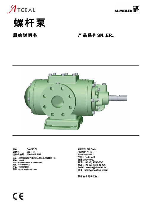
allweiler螺杆泵sn..er..原始说明书中文版
示图. 36 SN..ER..带有电加热器 . . . . . . . . . . . . . . . . . . . . . 41
4
产品系列SN..ER..
BA-213.06
650.0002 ZHS – 550 411
列表示图
列表 1 列表 2 列表 3 列表 4 列表 5 列表 6 列表 7 列表 8 列表 9 列表 10 列表 11 列表 12 列表 13 列表 14 列表 15 列表 16 列表 17 列表 18 列表 19 列表 20 列表 21 列表 22 列表 23 列表 24 列表 25 列表 26 列表 27 列表 28 列表 29 列表 30 列表 31
端面密封,淬火冷却(节流衬套) . . . . . . . . . . . . . 39 示图. 29 SN..ER..E QW,外置式轴承,可添加润滑油,
端面密封,淬火冷却(轴密封圈) . . . . . . . . . . . 39 示图. 30 SN..ER..E QW,淬火冷却连接,泵水平放
面密封 . . . . . . . . . . . . . . . . . . . . . . . . . . . . . . . . . . . . . 38 示图. 27 SN..ER..KA2,外置式轴承,不可添加润滑
油,轴封填料 . . . . . . . . . . . . . . . . . . . . . . . . . . . . . . . 38 示图. 28 SN..ER..E QT,外置式轴承,可添加润滑油,
面密封 . . . . . . . . . . . . . . . . . . . . . . . . . . . . . . . . . . . . . 35 示图. 16 SNS..ER..U,SNS 构造形式,内置式轴承,端
- 1、下载文档前请自行甄别文档内容的完整性,平台不提供额外的编辑、内容补充、找答案等附加服务。
- 2、"仅部分预览"的文档,不可在线预览部分如存在完整性等问题,可反馈申请退款(可完整预览的文档不适用该条件!)。
- 3、如文档侵犯您的权益,请联系客服反馈,我们会尽快为您处理(人工客服工作时间:9:00-18:30)。
ATEX Certified
粘
粘
A B
C
F
G
H
I K
N O L
A B
C F G H I K
N
O L D M E 浸没式泵过滤网
-5-
-6-
SMT16B系列 40bar 转速n=950rpm
对于高粘度介质及油气混合介质的应用请与我们联络获得适合的螺杆泵型号-7-
SMT16B系列 40bar 转速n=950rpm
Hylinco无须预先通知,将保留更新和更改产品规格的权利
-8-
SMT16B系列 40bar 转速n=950rpm
对于高粘度介质及油气混合介质的应用请与我们联络获得适合的螺杆泵型号-9-
SMT16B系列 40bar 转速n=950rpm
Hylinco无须预先通知,将保留更新和更改产品规格的权利
SMT16B系列 40bar 转速n=950rpm
对于高粘度介质及油气混合介质的应用请与我们联络获得适合的螺杆泵型号
SMT16B系列 40bar 转速n=950rpm
Hylinco无须预先通知,将保留更新和更改产品规格的权利
SMT16B系列 40bar 转速n=950rpm
对于高粘度介质及油气混合介质的应用请与我们联络获得适合的螺杆泵型号
SMT16B系列 40bar 转速n=950rpm
Hylinco无须预先通知,将保留更新和更改产品规格的权利
SMT16B系列 40bar 转速n=950rpm
对于高粘度介质及油气混合介质的应用请与我们联络获得适合的螺杆泵型号
SMT16B系列 40bar 转速n=950rpm
Hylinco无须预先通知,将保留更新和更改产品规格的权利
SMT16B系列 40bar 转速n=1450rpm
对于高粘度介质及油气混合介质的应用请与我们联络获得适合的螺杆泵型号
SMT16B系列 40bar 转速n=1450rpm
Hylinco无须预先通知,将保留更新和更改产品规格的权利
SMT16B系列 40bar 转速n=1450rpm
对于高粘度介质及油气混合介质的应用请与我们联络获得适合的螺杆泵型号
SMT16B系列 40bar 转速n=1450rpm
SMT16B系列 40bar 转速n=1450rpm
SMT16B系列 40bar 转速n=1450rpm
SMT16B系列 40bar 转速n=1450rpm
SMT16B系列 40bar 转速n=1450rpm
SMT16B系列 40bar 转速n=1450rpm
SMT16B系列 40bar 转速n=1450rpm
SMT16B系列 40bar 转速n=2950rpm
SMT16B系列 40bar 转速n=2950rpm
SMT16B系列 40bar 转速n=2950rpm
SMT16B系列 40bar 转速n=2950rpm
SMT16B系列 40bar 转速n=2950rpm
SMT16B系列 40bar 转速n=2950rpm
SMT16B系列 40bar 转速n=2950rpm
SMT16B系列 40bar 转速n=2950rpm
SMT系列 80bar 转速n=950rpm
SMT系列 80bar 转速n=950rpm
SMT系列 80bar 转速n=950rpm
SMT系列 80bar 转速n=950rpm
SMT系列 80bar 转速n=950rpm
SMT系列 80bar 转速n=950rpm
SMT系列 80bar 转速n=950rpm
SMT系列 80bar 转速n=950rpm
SMT系列 80bar 转速n=950rpm
SMT系列 80bar 转速n=950rpm
SMT系列 80bar 转速n=950rpm
SMT系列 80bar 转速n=950rpm
SMT系列 80bar 转速n=1450rpm
SMT系列 80bar 转速n=1450rpm
SMT系列 80bar 转速n=1450rpm。