DI-602LB+路由器硬件安装手册
DI-602LB+604LB+Web配置说明书

(7) 单击“确定”完成配置。 步骤三:测试计算机与路由器是否连通。 (1) 开始 运行 键入“cmd” 确定;
则表示 PC 已经和 DI-604LB+连接成功了。否则请检查下列可能性: DI-602LB+/DI-604LB+路由器面板上与计算机相连端口的指示灯是否亮起, 指示灯未亮表示物理上的连接不正常,可以换一根网线。 检查上述 TCP/IP 设置是否正确。 看 Windows XP 的网卡是否被禁用。
1.3 配置指南ቤተ መጻሕፍቲ ባይዱ
-3-
DI-602LB+/DI-604LB+ web 配置说明书
(2) 在命令提示符使用 ping 命令测试是否连通。执行:ping 192.168.2.1 若显示: Pinging 192.168.2.1 with 32 bytes of data: Reply from 192.168.2.1: bytes=32 time<10ms TTL=64 Reply from 192.168.2.1: bytes=32 time<10ms TTL=64 Reply from 192.168.2.1: bytes=32 time<10ms TTL=64 Reply from 192.168.2.1: bytes=32 time<10ms TTL=64 Ping statistics for 192.168.2.1: Packets: Sent = 4, Received = 4, Lost = 0 (0% loss), Approximate round trip times in milli-seconds: Minimum = 0ms, Maximum = 0ms, Average = 0ms
DI-604LB+路由器硬件安装手册

DI-604LB+ 路由器硬件安装手册目录目录第1章 DI-604LB+路由器概述 (1)1.1 标准配置时的外形说明 (1)1.1.1 Reset按钮和SYS指示灯 (1)1.2 路由器系统特性参数 (3)1.3 ROHS说明 (4)第2章安装准备 (5)2.1 使用注意事项 (5)2.2 安全建议 (5)2.3 一般场所要求 (6)2.3.1 场所环境 (6)2.3.2 场所配置预防 (6)2.3.3 电源考虑 (7)2.4 安装工具和设备 (7)第3章安装路由器 (8)3.1 DI-604LB+路由器的安装流程 (8)3.2 路由器机箱安装 (8)3.2.1 安装机箱于桌面 (8)3.3 连接接口 (8)3.3.1 连接PC机 (9)3.3.2 连接快速以太网接口 (9)3.4 安装后检查 (11)第4章硬件故障分析 (12)4.1 故障隔离 (12)4.1.1 电源故障 (12)4.1.2 端口、电缆和连接故障 (12)4.1.3 系统异常故障 (12)4.2 指示灯说明 (12)第1章 DI-604LB+路由器概述本节主要对DI-604LB+路由器总体方面的特性、参数作了说明和介绍。
1.1 标准配置时的外形说明DI-604LB+配备5个10/100M自适应以太网口,默认配置的wan口为2个,可以通过set-wan-port命令,最多可配置4个wan口(具体端口的使用请详见“命令手册”中的“高级配置命令”)。
此外,一个电源插孔,一个电源开关(ON:开;OFF:关),一个接地柱以及通风孔、条形通风孔(有助于形成对流气流,构成良好的路由器散热环境)。
说明:计算机连接到DI-604LB+路由器的快速以太网端口TP2上进行网络配置。
DI-604LB+路由器的前面板如下图所示:图 1-1 DI-604LB+ 路由器的前面板示意图后面板示意图如下:图 1-2 DI-604LB+ 路由器后面板示意图1.1.1 Reset按钮和SYS指示灯Reset按钮有两种操作方式:第一种操作方式只恢复系统的配置;第二种操作方式恢复系统的配置及软件版本。
路由器安装说明
1.1,首先将宽带猫与路由器的WLAN端口连接,可使用猫随机带的连接线。
2.2,用直连网线将路由器的一个Lan口与交换机的UpLing口连接。
还用直连网线连接交换机的普通口和电脑。
这样硬件环境就做好了。
如果你的机器比较少,也就2、3台的话,没有必要加交换机,用直连网线将路由器的一个Lan口与一台电脑连接即可。
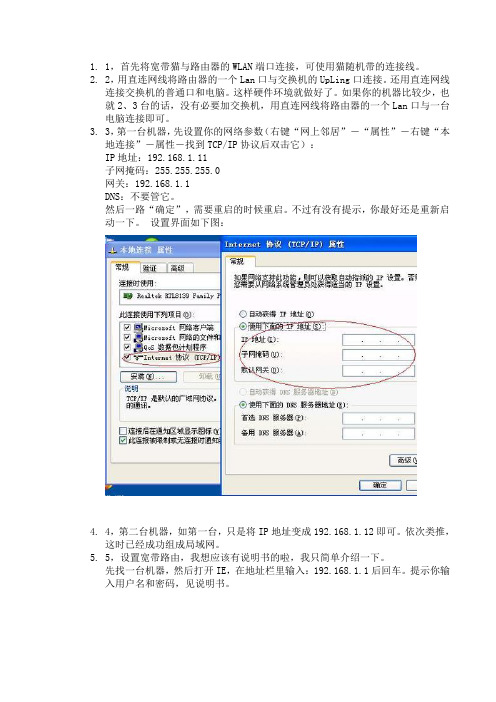
3.3,第一台机器,先设置你的网络参数(右键“网上邻居”-“属性”-右键“本地连接”-属性-找到TCP/IP协议后双击它):IP地址:192.168.1.11子网掩码:255.255.255.0网关:192.168.1.1DNS:不要管它。
然后一路“确定”,需要重启的时候重启。
不过有没有提示,你最好还是重新启动一下。
设置界面如下图:4.4,第二台机器,如第一台,只是将IP地址变成192.168.1.12即可。
依次类推,这时已经成功组成局域网。
5.5,设置宽带路由,我想应该有说明书的啦,我只简单介绍一下。
先找一台机器,然后打开IE,在地址栏里输入:192.168.1.1后回车。
提示你输入用户名和密码,见说明书。
采用宽带路由方式。
如果你不想自己设置,可以在购买宽带的同时让技术人员帮你设置好。
同时这种方式带来的好处还有就是稳定!还有就是省力,你不需要每次上网都要拨号了,这都由宽带路由来自动替你完成,而且宽带路由还有断线重拨功能,省去了多少麻烦?接下来就是安全,你暴露在Internet上的IP是你路由的IP,而非机器本身的IP,这样你就无形中被保护起来。
再有就是不违反电信或者网通的规定,即使他限制了MAC地址也没用,因为路由本身是有MAC地址的。
1、把宽带猫的输出线,插到宽带路由器的WAN端口上,用网线把路由器LAN端口同电脑网卡相连。
2、启动宽带猫和路由器的电源。
3、配置路由器,进行如下设置(具体应按你所使用的路由器说明书去做):1)在IE窗口地址栏,输入192.168.1.1,打“转到”打开要求输入用户名和密码的对话框。
WG602 v3 无线路由器安装指南说明书

When prompted,enter admin for the user name and Click the IP Settings link and configure the IP Settings according to your network setup.3Deploy the WG602 Access Pointa.Disconnect the WG602 and position it where you will deploy it.The best location is elevated at the center of your wireless coverage area.b.Lift the antenna so that it is vertical.c.Connect an Ethernet cable from your WG602 Access Point to a LAN port on your router,switch,or hub.Note:By default,the WG602 is a DHCP client.If there is no DHCP server in the network,the WG602 uses 192.168.0.227 as its IP address.If your network used different addressing,you will need to configure the WG602 accordingly.d.Connect the power adapter to the wireless access point and plug the power adapter in to a power outlet.The power,LAN,and wireless lights should light up.4Verify Wireless ConnectivityUsing a computer with an 802.11b or 802.11g wireless adapter withthe correct wireless settings needed to connect to the WG602 (SSID,MAC ACL,WEP ,WPA,etc.),verify connectivity by using a browser such as Netscape ®or Internet Explorer to browse the Internet,or check for file and printer access on your network.Note:If you cannot connect,see the Troubleshooting Tips on the next page or the Reference Manual on the 54 Mbps Wireless Access Point Resource CD .September 2004Technical SupportPLEASE REFER TO THE SUPPORT INFORMATION CARD THAT SHIPPED WITH YOUR PRODUCT.By registering your product at /register ,we can provide you with faster expert technical support and timely notices of product and software upgrades.NETGEAR,INC.Support InformationPhone:1-888-NETGEAR (For US & Canada only) - 24 x 7 phone support See Support information card for other countries.E-mail:*******************(24x7onlinesupport)©2004 NETGEAR,GEAR,the Netgear logo,The Gear Guy and Everybody's Connecting are trademarks or registered trademarks of Netgear,Inc.in the United States and/or other countries.Microsoft and Windows are registered trademarks of Microsoft Corporation in the United States and/or other countries.Other brand and product names are trademarks or registered trademarks of their respective rmation is subject to change without notice.All rights reserved.I cannot configure the wireless access point from a browser.There is a configuration problem.Check these items:• The WG602 is properly installed,LAN connections are OK,and it ispowered on.Check that the LAN port LED is green to verify that the Ethernet connection is OK.• If you are using the NetBIOS name of the WG602 to connect,ensure that your PC and the WG602 are on the same network segment or that there is a WINS server on your network.• If your PC uses a Fixed (Static) IP address,ensure that it is using anIP Address in the range of the WG602.The WG602 default IP Address is 192.168.0.227 and the default Subnet Mask is255.255.255.0.See the Reference Manua l on the 54 Mbps Wireless Access Point Resource CD for more details .I cannot access the Internet or the LAN with a wireless capable computer.There is a configuration problem.Check these items:•You may not have restarted the computer with the wireless adapter to have TCP/IP changes take effect.Restart the computer.• The computer with the wireless adapter may not have the correctTCP/IP settings to communicate with the network.Restart thecomputer and check that TCP/IP is set up properly for that network.The usual setting for the Windows Network Properties is to be set to “Obtain an IP address automatically.”• The access point’s default values may not work with your network.Check the access point default configuration against the configura-tion of other devices in your network.• For full instructions on changing the access point’s default values,seethe Reference Manual on the 54 Mbps Wireless Access Point Resource CD .。
B-LINK无线路由器的安装与设置.doc

B-LINK无线路由器的安装与设置2、根据ip查看路由器地址:若你的ip是:192.168.2.100,那么路由器的ip一般就是:192.168.2.1。
3、在IE地址栏中输入地址:192.168.2.1。
4、弹出路由器登陆界面,输入路由器的默认用户名:admin 密码:admin(如果不正确,就看路由器背面)。
5、以上方法行不通,在重置路由器。
地址,账号,密码都在路由器背面。
【设置路由器拨号】:电脑ip、dns设置自动获取。
1、进入路由器。
在【设置向导】里,选择【PPOE拨号】(有些是ADSL拨号)这一项,按提示步骤输上你上网的用户名和密码,保存。
2、在【网络参数】--【WAN设置】里,选【正常模式】,在【连接】的三个选项,选择【PPOE拨号】这一项。
下面就是选择【自动连接】,保存,退出。
3、如果想用无线wifi,你的路由器就必须带无线路由功能,在无线设置---无线基本设置,把无线路由功能打开就行了,在这里,无线信号信到改为:1、6、11其中1个。
防干扰最强。
你也可以设置无线上网连接的密码。
希望以上的内容能帮助到你。
B-LINK无线路由器怎么设置WIFIB-LINK无线路由器怎么设置WIFI1、进入路由器地址,连接好无线路由器后,在浏览器输入在路由器看到的地址,一般是192.168.1.1(当然如果你家是用电话线上网那就还要多准备一个调制调解器,俗称猫)。
2、输入相应的账号密码,进入后会看到输入相应的帐号跟密码,一般新买来的都是admin。
3、选择设置向导,确实后进入操作界面,你会在左边看到一个设置向导,进击进入(一般的都是自动弹出来的)。
4、进入上网方式设置,设置向导的界面。
5、点击下一步,进入上网方式设置,我们可以看到有三种上网方式的选择,如果你家是拨号的话那么就用PPPoE。
动态IP 一般电脑直接插上网络就可以用的,上层有DHCP服务器的。
静态IP一般是专线什么的,也可能是小区带宽等,上层没有DHCP 服务器的,或想要固定IP的。
无线路由器硬件安装设置图解

无线路由器硬件安装设置图解1、确认宽带线路正常:无线宽带路由器可以让您将家中的计算机共享高速宽带网络连结至互联网;但在此之前,您必须先具备一部基于以太网络的Cable/DSL Modem(使用RJ-45 接头),并确定您的宽带网络在只有连接一台计算机的时候,已经可以依照网络服务提供者(I SP)所提供的方式正常连接到互联网。
2、删除拨接(号)软件:建议您使用Windows 2000/XP 操作系统来设定无线路由器,若您使用的是Windows 98 se2/ME 操作系统,且已安装ISP 所提供的ADSL 拨接(号)软件,请先将其删除后再开始无线路由器的连接设定。
3、系统需求:本产品使用浏览器进行设定安装,不需要额外安装任何程序供连接使用,在开始设定之前强烈建议您先将浏览器升级至I nternet Explorer 5.5/6.0 sp1 以上版本。
4、使用者不需要连上互联网,只需要透过局域连接(LAN)即可设定无线路由器。
5、无线路由器硬件只需设定一次,其余要透过无线路由器的计算机或设备只需做相关的TCP/IP 设定即可。
硬件装置连接设定示范1. 将电源接头接上无线路由器背面的电源孔,然后将另一端接上电源插座。
请稍候约30 秒,待无线路由器激活完毕后,再进行下一步连接动作。
2. 请将连结至ADSL/Cable Modem的网络线接上广域网端口上(W AN)。
*现在市场上的无线路由器WAN 端口一般都支持Auto MDI-IX。
4. 完成连接设定之后,无线路由器的指示灯应该为:1)Power 灯恒亮。
2)Status 灯约每秒闪烁一次。
3)WAN 灯不定时闪烁。
4)WLAN 灯闪烁。
5)有接上LAN 1-4 指示灯闪烁。
3. 将与计算机或设备连结的网络线接上局域网端口1-4(LAN )任意一个端口。
*现在市场上的无线路由器LAN 端口一般都支持Auto MDI-IX。
5. 将已安装好无线网卡的计算机或设备拿至无线路由器附近,无线网卡与无线路由器的无线网络检测一下信号的强度。
Ruijie RG-EAP602系列接入点硬件安装及参考指南说明书

Ruijie RG-EAP602 Series Access Points Hardware Installation and Reference Guide·Copyright statementRuijie Networks©2021Ruijie Networks reserves all copyrights of this document. Any reproduction, excerption, backup, modification, transmission, translation or commercial use of this document or any portion of this document, in any form or by any means,without the prior written consent of Ruijie Networks is prohibited.Exemption statementThis document is provided “as is”. The contents of this docu ment are subject to change without any notice. Please obtainthe latest information through the Ruijie Networks website. Ruijie Networks endeavors to ensure content accuracy and willnot shoulder any responsibility for losses and damages caused due to content omissions, inaccuracies or errors.·PrefaceThank you for using our products. This manual will guide you through the installation of the access point.ScopeIt is intended for the users who have some experience in installing and maintaining network hardware. At the same time, itis assumed that the users are already familiar with the related terms and concepts.Obtaining Technical Assistance●Ruijie Networks Website: https:///●Technical Support Website: https:///support●Case Portal: https://●Community: https://●Technical Support Email: *****************************●Skype: *****************************Related DocumentsDocuments DescriptionConfiguration Guide Describes network protocols and related mechanisms that supported by the product, with configuration examples.Command Reference Describes the related configuration commands, including command modes, parameter descriptions, usage guides, and related examples.Documentation ConventionsThe symbols used in this document are described as below:This symbol brings your attention to some helpful suggestions and references.This symbol means that you must be extremely careful not to do some things that may damage the device or cause data loss.·1 Product OverviewThe RG-EAP602, adhering to the latest 802.11ac Wave2 standard, delivers up to 866Mbps@5G + ************access rate. EAP602 supports security, radio frequency (RF) control, mobile access, Quality of Service (QoS) andseamless roaming. Teaming up with Ruijie RG-WS Wireless Controller Series, wireless data forwarding, highperformance security and access control can be accomplished with ease. EAP602 supports PoE to take over challengesin a wide variety of deployment scenarios, including large-scaled campuses, enterprises, hospitals and WIFI hotspots.1.1 Technical SpecificationsTable 1-1 RG-EAP602 Technical SpecificationsModel RG-EAP602Dimensions 222 mm × 200 mm × 166 mmAccess Rate Built-in antenna:1166Mbps 2.4GHz: up to 300Mbp5GHz: up to 866MbpsOperating Frequency 802.11b/g/n: 2.4 GHz to 2.483 GHz802.11a/n/ac: 5.150 GHz to 5.350 GHz, 5.47 GHz to 5.725 GHz, 5.725 GHz to 5.850 GHz (Country-Specific)Maximum TransmitPower500mWAntenna Type Built-in omnidirectional antennaAntenna Gain 2.4 GHz: 3 dBi 5 GHz: 4 dBiCoverage Angle 2.4G: E:30°; H:360°5G: E:30°; H:360°Ports One 10/100/1000 Base-T uplink Ethernet port One 10/100/1000 Base-T Ethernet portFIT/FAT Mode Not supportLED System and port status indicators PoE Power Supply IEEE 802.3afPower Consumption Maximum: 12.95WTemperature Operating: -40°C to 65°C (-40°F to 149°F) Storage: -40°C to 85°C (-40°F to 185°F)Humidity Operating: 0% to 100% (non-condensing) Storage: 0% to 100% (non-condensing)IP Rating IP68 Weight < 1kg (host)Safety Standards GB4943EN60601-1-2 UL/CSA 60950-1 EN/IEC 60950-1·EN/IEC 60950-22 EMC StandardsGB9254-2008 EN301 489EN 55022 FCC Part15 RSS-210Table 1-2 LEDs of RG-EAP602 IndicatorStatus MeaningWiFi (Blue)Blinking Data is transmitted by WiFi.Solid on WiFi is enabled and no data is transmitted. OffWiFi is disabled.WARN(Red)BlinkingInitialization: blinking at a rate of 1Hz (on for 505ms and off for 505ms).Restore factory settings: blinking at a rate of 14Hz (on for 20ms and off for 50ms).System upgrade: blinking at a rate of 10Hz (on for 40ms and off for 60ms). Solid on CWMP is not connected.Off Powered off or initialization test is normal. LAN 1(Blue)BlinkingThe port is up and data is transmitted. Solid on The port is up and no data is transmitted. Off The port is not connected.LAN 2(Blue)BlinkingThe port is up and data is transmitted. Solid on The port is up and no data is transmitted. OffThe port is not connected.1.2 Product AppearanceFigure 1-1 Product Appearance of the RG-EAP602·Figure 1-2 Ports of RG-EAP602Note1. 10/100/1000BASE-T Ethernet port2. DC power supply port3. 10/100/1000BASE-T Ethernet port/PoE port4. Reset button5. Waterproof cap1.3 Power SupplyThe AP supports 802.3af PoE or 12V DC power supply (If needed, you can buy the adapter from Ruijie).When PoE power supply is adopted, please make sure the peer end support 802.3af too. The lowest current output requirement for a DC power supply is 1.5A.·2 Preparing for InstallationTo prevent device damage and physical injury, please read carefully the safety recommendations described in thischapter.Recommendations do not cover all possible hazardous situations.2.1 Grounding and Lightning Protection●Ensure that both the power-receiving end and the power-supplying end are well-grounded.●Keep the grounding connection within 30 m, and use a 40mm x 4mm or 50mm x 5mm ground bar of hot-dipzinc-coated flat steel sheet.●When the connection cable between the main grounding conductor and local equipotential earthing terminal board(LEB) on each floor is shorter than 2 meters, use a stranded copper wire with a sectional area not less than 1.318mm2 (16 AWG) for the connection cable.●Use a shielded network cable if possible, ensure that devices connected to both ends of the shielded network cableare reliably grounded, and make sure that the sheath of the shielded network cable is also grounded if possible. If noshielded network cable is available, wire the network cable through a steel pipe and bury the steel pipe for lead-in,and properly ground both ends of the steel pipe.●No additional lightning protector is required as a high-profile lightning protector is built in the RG-EAP602, and thepower port support 6kV lightning protection. If a lightning protector of a higher profile is available, configure thelightning protector optionally. Before the configuration, connect the lightning protector to the ground cable.●Use a power cable with the PE end to ground the power supply (AC). Ensure that the PE end is properly grounded,with a ground resistance less than 5 ohms. Do not use a two-wire power cable with only the live (L) wire and naught(N) wire. Do not connect the N wire to the protection ground cable of other communication devices, and ensure thatthe L wire and N wire are properly connected.●Ensure that the ground resistance is less than 5 ohms. In areas with high soil resistivity, reduce the soil resistivity viameasures such as spreading resistivity reduction mixture around the grounding conductor.2.2 Preparing the Installation Site●Do not expose the AP to high temperature, dust, or harmful gases.●Do not install the AP in an area prone to fire or explosions.●Keep the AP away from EMI sources such as large radar stations, radio stations, and substations.●Do not subject the AP to unstable voltage, vibration, and noises.●Keep the AP at least 500 meters away from the ocean and do not face it towards the sea breeze.●The installation site should be protected from water and flooding, seepage, dripping, or condensation.●The installation site should be selected according to network planning, communications equipment features andconsiderations such as climate, hydrology, geology, earthquake, electric power, and transportation.·2.2.1 Temperature and HumidityTable 2-1 Required Temperature and Humidity for the RG-EAP602 SeriesOperating Temperature -40°C to 65°C (-40°F to 149°F)Operating Humidity 0% to 100% (non-condensing)2.2.2 Outdoor InstallationThe AP can be mounted on a wall or a pole.2.2.3 WaterproofUse a seal plug to seal the unused ports.After using the reset button, please ensure that the cap is put back.Use a waterproof plug to connect cables to the AP. For details, see Chapter 3 “Installing the Access Point”.2.2.4 EMIAll interference sources (from outside or inside of the device or application system) affect the device by capacitivecoupling, inductive coupling, or electromagnetic waves.Electromagnetic interference (EMI) occurs due to electromagnetic radiation or conduction, depending on the transmissionpath.Radiation interference occurs when energy (usually radio frequency energy) is emitted from a device and propagatedthrough space to disrupt other devices. The interference source can be part of disrupted system or a fully electricallyisolated unit. Conduction interference occurs when interference is transferred from one unit to another through cables,which are usually electromagnetic wires or signal cables connected between the source and the device(s) experiencing interference. Conduction interference often affects the power supply of the device. It is eliminated by using filters.Radiation interference can influence the path of any signal from the device and is difficult to shield.●Take effective measures against interference from the power grid.●Keep the AP far away from the grounding or lightning protection devices for power equipment.●Keep the AP away from high-power radio stations, radar stations, and high-frequency high-current devices.●Take electrostatic shielding measures.2.3 Installation ToolsTable 2-2 Installation ToolsTools Marker, Phillips (crosshead) screwdriver, slotted screwdriver, drill, paper knife, crimping pliers, diagonal pliers, wire stripper, network cable tester, related power and fiber cables, wrench, hammer, cable ties, ESD tools, multimeter, waterproof duct tape, waterproof plasterThe tool kit and cables are customer supplied.·2.4 Checking before InstallationPlease check your materials carefully against the package contents. If there are any errors, please contact your distributor.·3 Installing the Access PointBefore installing the AP, make sure you have carefully read the requirements described in Chapter 2.3.1 Installation Flowchart3.2 Before You BeginBefore you install the AP, verify that all the parts in the package contents are there and make sure that:●The installation site meets temperature and humidity requirements.●The installation site is equipped with a proper power supply.●Network cables are in place.·3.3 PrecautionsRG-EAP602 can be mounted on a wall and a pole (diameter: 50mm to 70mm, thickness: ≥2.5mm). Otherwise, the APcould fall down and cause injuries. The installation site can vary due to on-the-spot surveys conducted by technicalpersonnel.Please make full preparations as described in Chapter 2 and observe the following precautions before installing the AP.●Before connecting the power supply, make sure the external power supply matches the power module inside the AP.●Before connecting the power cord, make sure the power switch is in the OFF position.●When connecting a wire to a binding post, make sure their colors are the same.●Make sure the power supply is properly connected.3.4 Installing the AP●Wall mountUse M8 x 60 screws to implement the wall mount.a. Attach the bracket to the wall and mark the screw hole locations.Figure 3-1 Installing the Bracketb. Align the host with bracket and mounting plate to the bracket on the wall, and tighten the M8×40 screws to completeinstallation.Figure 3-2 Mounting the Bracket on Wall·Pole mount (Vertical)a. Attach the bracket to a pole with hose clamps and fasten the clamps with screws and nuts.Figure 3-3 Mounting the Bracket on a Poleb. Align the host with bracket and mounting plate to the bracket on the pole, and tighten the M8×40 screws to completeinstallation.Figure 3-4 Vertical Pole Mounting·Pole mount (Horizontal)Figure 3-5 Mounting the Bracket on a PoleFigure 3-6 Horizontal Pole MountingThe horizontal pole mounting is the same with the vertical pole mounting.·3.5 Connecting CablesConnecting the network cableWaterproofing material is customer-supplied.1) Trim the network cable according to the distance between the AP and the power supply. And put the trimmed cablethrough the bracket.2) Thread the cable with an unprocessed RJ45 through the waterproof plug in the order shown in the Figure 3-7.Figure 3-7 Threading the Network Cable3) After the cable passes through the waterproof plug, process the RJ45.4) Connect the cable with the LAN1/PoE/uplink port of AP, and tighten the waterproof plug in the order of B, C and D tocomplete the installation.5) To install the waterproof port not connected with the network cable: Insert the waterproof rubber rod into the ring,and tighten them in order.Make sure the plug is correctly inserted. The plug can be damaged if the liquid-tight adapter is improperly tightened.Before removing the network cable, dismantle the waterproof plug first and then the plug.NoteThe product should not be installed in the place prone to water accumulation, seepage, dripping, and condensation.The product is recommended to be installed horizontally.If any requirement above can not be fulfilled, please use waterproof duct tape and waterproof plaster.·Appendix A Connectors and Media1000BASE-T/100BASE-TX/10BASE-TThe 1000BASE-T/100BASE-TX/10BASE-T is a 10/100/1000 Mbps auto-negotiation port that supports auto MDI/MDIX.Compliant with IEEE 802.3ab, 1000BASE-T requires Category 5e 100-ohm UTP or STP (STP is recommended) with amaximum distance of 100 meters (328 feet).1000BASE-T requires all four pairs of wires be connected for data transmission, as shown in Figure A-1.Figure A-1 1000BASE-T Connection10BASE-T uses Category 3, 4, 5 100-ohm UTP/STP and 1000BASE-T uses Category 5 100-ohm UTP/STP for connections. Both support a maximum length of 100 meters. Table A-1 shows 100BASE-TX/10BASE-T pin assignments.Table A-2 100BASE-TX/10BASE-T Pin AssignmentsFigure A-3 shows wiring of straight-through and crossover cables for 100BASE-TX/10BASE-T.Figure A-3 100BASE-TX/10BASE-T ConnectionFiber Connection·You can choose to use single mode or multimode fibers according to the transceiver module types. Figure A-4 showsconnection of fiber cables.Figure A-4 Fiber Connection··Hardware Installation and Reference Guide Appendix B Mini-GBIC Module SpecificationsAppendix B Mini-GBIC Module SpecificationsRuijie provides various Gigabit SFP transceivers (Mini-GBIC modules) for interfaces of wireless access controllers. You can select the most suitable SFP modules as needed. This appendix describes the models and specifications of some of the Gigabit SFP transceivers for your reference.Mini-GBIC (SFP) Models and SpecificationsTable B-1 Models and Specifications of SFP ModulesMini-GBIC(SFP) Wavelength (nm) Fiber Type Core Size (micron) Modal Bandwidth (MHz/km) Cable Distance Max Transmit (dBm) Max Receive (dBm)StandardsFE-SFP-LX-MM 13101310 MMF 1 62.5/ 125 — 2 km -14 -14 IEEE802.3FE-SFP-LH15-S M13101310SMF 29/ 125 — 15 km -8 -8MINI-GBIC-SX-MM850850MMF 162.562.5 50.0 50.0 160 200 400 500 220 m 275 m 500 m 550 m -4 -17MINI-GBIC-LX-S M1310 1310MMF 1 SMF 262.550.0 50.0 9/10 500 400 500 — 550 m 550 m 550 m 10 km -3 -20MINI-GBIC-LH40-SM1310 1310 SMF 29/ 125—40 km 3 -3 MINI-GBIC-ZX50-SM1550 1550 SMF 2 — — 50 km0 -22 MINI-GBIC-ZX80-SM1550 80 km 4.7 -22 MINI-GBIC-ZX100-SM1550 100 km5 -9 Mini-GBIC-GT —Cat 5 UTP— — 100 m——1 MMF=Multimode fiber2 SMF=Single mode fiberWhen using shorter distances of single-mode fiber for optical SFP transceivers with cable distance greater than 40km (including 40 km), you may need to insert an in-line optical attenuator in the link to avoid overloading the receiver.。
实验二十三 DI-602LB+使用双线路连接的配置.pdf
实验二十三 DI-602LB+ 使用双线路连接的配置一、产品简介:DI-602LB+ / DI-604LB+是专门为网吧和中小型企事业单位推出的一款性价比极高的智能型宽带路由器。
拥有强大的数据处理能力,支持多种主流宽带接入技术,并且内置丰富的防火墙功能,能够有效防止病毒攻击及非法入侵。
它采用了MARVELL 专用高速交换芯片,配合专门针对宽带接入优化操作系统,可以满足200个用户并发同时上网而不会出现掉线,延迟大的现象。
二、实验目的:1、了解DI-602LB+/DI-604LB+双WAN 口NAT 的配置方法,并验证负载均衡功能。
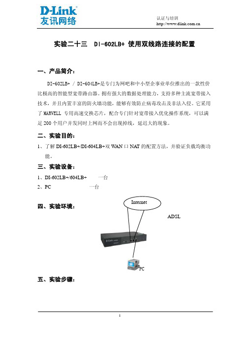
三、实验设备:1、DI-602LB+/604LB+ 一台2、PC 一台1四、实验环境:ADSLPC五、实验步骤:1.在默认的出厂状态下,DI-602LB+需要通过它的TP2端口来进行配置工作,其默认的IP地址为192.168.2.1,所以在对设备进行参数配置之前必须将和它连接的计算机网卡的IP地址预先设置为192.168.2.x ,以便通过计算机可以顺利的访问到DI-602LB+。
如下所示,利用“网上邻居”将计算机的IP地址设为192.168.2.10,并将网卡通DI-602LB+的TP2端口相连。
2.当在DOS界面下可以从计算机上Ping通192.168.2.1这个地址时,说明计算机已经能够同DI-602LB+进行通讯了,这时通过在IE浏览器中键入192.168.2.1这个IP地址,就可以进入到设备的配置界面了。
进入配置界面默认的用户名和密码都是admin23.进入配置界面的显示如下,我们可以按照上面的提示来进行参数的设置工作。
34.在上面的界面中点击“下一步”,进入如下的页面,在这里用户可以根据自己的应用环境来选择是使用“典型配置”(单线路),“配置向导”(双线路)还是“高级配置”方式。
由于我们在本文中介绍的是使用两条线路上网的设置方法,所以我们选择其中的第二项“配置向导”项。
- 1、下载文档前请自行甄别文档内容的完整性,平台不提供额外的编辑、内容补充、找答案等附加服务。
- 2、"仅部分预览"的文档,不可在线预览部分如存在完整性等问题,可反馈申请退款(可完整预览的文档不适用该条件!)。
- 3、如文档侵犯您的权益,请联系客服反馈,我们会尽快为您处理(人工客服工作时间:9:00-18:30)。
DI-602LB+ 路由器硬件安装手册目录目录第1章 DI-602LB+路由器概述 (1)1.1 标准配置时的外形说明 (1)1.1.1 Reset按钮和SYS指示灯 (1)1.2 路由器系统特性参数 (3)1.3 ROHS说明 (4)第2章安装准备 (5)2.1 使用注意事项 (5)2.2 安全建议 (5)2.3 一般场所要求 (6)2.3.1 场所环境 (6)2.3.2 场所配置预防 (6)2.3.3 电源考虑 (7)2.4 安装工具和设备 (7)第3章安装路由器 (8)3.1 DI-602LB+路由器的安装流程 (8)3.2 路由器机箱安装 (8)3.2.1 安装机箱于桌面 (8)3.3 连接接口 (8)3.3.1 连接监控口 (9)3.3.2 连接快速以太网接口 (10)3.4 安装后检查 (12)第4章硬件故障分析 (13)4.1 故障隔离 (13)4.1.1 电源故障 (13)4.1.2 端口、电缆和连接故障 (13)4.1.3 系统异常故障 (13)4.2 指示灯说明 (13)第1章 DI-602LB+路由器概述本节主要对DI-602LB+路由器总体方面的特性、参数作了说明和介绍。
1.1 标准配置时的外形说明DI-602LB+配备3个10/100M自适应以太网口。
此外,一个电源插孔,一个电源开关(ON:开;OFF:关),一个接地柱以及通风孔、条形通风孔(有助于形成对流气流,构成良好的路由器散热环境)。
说明:计算机连接到DI-602LB+路由器的快速以太网端口TP2上进行网络配置。
DI-602LB+路由器的前面板如下图所示:图 1-1 DI-602LB+路由器的前面板示意图后面板示意图如下:图 1-2 DI-602LB+路由器后面板示意图1.1.1 Reset按钮和SYS指示灯Reset按钮有两种操作方式:第一种操作方式只恢复系统的配置;第二种操作方式恢复系统的配置及软件版本。
当路由器的软件系统出现严重异常情况,导致无法启动时,可按照第一种操作方式来恢复系统的缺省配置或用户以前保存的配置文件。
如果第一种操作完成后,系统仍然无法正常启动,请按照第二种操作方式同时进行软件版本及系统配置的恢复工作。
两种操作方式详细内容如下:(1) 第一种操作方式步骤:第一种操作方式分两种情况:一种恢复缺省配置,另一种恢复用户以前保存的配置。
下面分别讲述两种情况的操作步骤。
a) 恢复缺省配置步骤如下:A. 关闭DI-602LB+电源。
B. 按住RESET按钮不放。
C. 打开电源,等待SYS灯点亮。
D. 当SYS灯点亮时,3秒钟之内放开RESET按钮,切记不可久按。
E. 等待2分钟。
F. 2分钟过后,冷启动路由器。
注意:缺省配置中TP2口的IP地址为192.168.2.1。
b) 恢复用户以前保存的配置步骤如下:A. 装有TFTP server软件的PC与DI-602LB+的TP2口背靠背相连,确保LINK/ACT灯亮。
B. PC地址配置为192.2.2.40。
C. 将用户以前保存的配置文件放置在TFTP server的工作目录下,要保证配置文件名为startup-config。
D. 关闭DI-602LB+电源。
E. 按住RESET按钮不放。
F. 打开DI-602LB+电源,等待SYS灯亮。
G. 当SYS灯点亮时,3秒钟之内放开RESET按钮,切记不可久按。
H. 等待2分钟。
I. 2分钟过后,冷启动路由器。
注意:1) 放开RESET按钮之后,一定要等待2分钟后,再启动路由器,否则将会造成严重后果。
2) SYS灯点亮后(非闪烁)3秒钟内一定要放开RESET按钮,如果一直等到灯闪烁后再放开会进入第二种操作方式。
假如此时TFTP server没有与DI-602LB+设备相连,或者TFTP server目录下没有软件版本router.bin,会造成系统状态异常,解决办法为重新关闭电源,连接好TFTP server,将router.bin放置到TFTP server的工作目录下,严格按照第二种操作方式进行操作,恢复系统正常运作。
3) 系统中默认的配置文件名为startup-config。
(2) 第二种操作方式步骤(恢复系统软件及配置文件):A. 装有TFTP server软件的PC与DI-602LB+的TP2口背靠背相连,确保LINK/ACT灯亮。
PC地址配置为192.2.2.40。
B. 将用户以前保存的配置文件及软件版本router.bin放置在TFTP server的工作目录下,要保证配置文件名为startup-config。
(如果TFTP server目录下没有该配置文件,系统将自行恢复系统缺省的配置,TP2口设置为192.168.2.1)C. 关闭DI-602LB+电源。
D. 按住RESET按钮不放。
E. 打开DI-602LB+电源,等待SYS开始闪烁。
(大概需要10~15秒钟)F. 当SYS灯开始闪烁时,放开RESET按钮。
G. 等待SYS灯熄灭。
(该过程大概需要2~3分钟)H. SYS灯熄灭后,冷启动路由器。
注意:1) 软件版本的文件名一定为router.bin,不是该文件名的软件版本要改为该文件名,否则不能升级。
2) 系统在导入配置文件startup-config和软件版本时,用户不能关闭电源,否则会导致路由器硬件损坏。
1.2 路由器系统特性参数DI-602LB+路由器的特性参数表:表 1-1 DI-602LB+路由器硬件特性表存储器Flash Memory:4M Bytes;SDRAM:32Mbytes;固定配置3个10/100M快速以太网端口外形尺寸340mm×200mm×44mm工作温/湿度0℃~40℃;10%~85%无冷凝存储温/湿度-20℃~65℃;5%~95%无冷凝电源特性交流输入电压:100~240V,输入频率47~63Hz输入电流:1A/230V电源消耗最大10W1.3 ROHS说明第2章安装准备2.1 使用注意事项与其它电子产品类同,快速而频繁地开启和关闭电源易对半导体芯片产生损伤。
需重新开启DI-602LB+系列路由器时,请在关闭电源3~5秒后再打开电源开关;请勿剧烈碰撞或从高处摔落DI-602LB+系列路由器,这样的操作可能损坏路由器内部硬件;请使用正确的外部接线端口与DI-602LB+系列路由器相连。
不要将电话线插头(RJ11四线插头)插入路由器以太网双绞线接口或监控口;不要将以太网双绞线插头插入监控口(RJ45八线插座);同样也不要将监控口电缆插入以太网双绞线接口(RJ45八线插座);以上的操作以及其它的错误操作都可能引发端口内部元器件的损伤。
2.2 安全建议根据以下原则确保安全机箱安装过程中和安装完成后请保持无尘、清洁;将机盖放到安全的地方;把工具放在不易被碰落的地方;不要穿宽松的衣服,以免绊住机箱,系好领带或围巾,卷起袖子;如果所处环境可能伤害眼睛,请务必戴上防护眼镜;不要做可能引起人身伤害或损坏设备的操作。
安全警告本节中出现的安全警告信息指:如果操作不当,可能引起人身伤害。
仔细阅读安装指南,然后再对系统进行操作;只有经培训合格的人员才能安装或更换路由器;对机箱进行操作或接近电源工作前,请拔掉交流电源插头,断开直流连接;产品的最终配置必须符合国家适用的所有法律和规范。
带电操作安全原则对带电设备进行操作前,摘下首饰(如:指环、项链、手表、手链等)。
金属物品接触到“电源”与“地”时可能引起短路导致元器件损坏;对机箱进行操作或近电源工作之前,拔掉交流电源插头,断开直流电源;当接上电源时,不要触摸电源,当心触电;设备和电源插座间不正确的连接可能导致危险情况;设备只允许经培训合格的人员操作和维护;系统上电前,请认真阅读安装指南。
注意:1) 仔细察看潜在的危险:如潮湿的地板、不接地的扩展电源线、磨损的电源线;2) 将紧急开关放在工作间,以便事故发生时,迅速切断电源;3) 进行安装/拆卸机箱或接近电源工作前,断开路由器电源开关,拔掉电源线;3) 如果有潜在的危险,请不要单独工作;4) 进行检查前,务必请断开电源;5) 如果事故发生,采取以下措施。
A.关掉系统电源;B.报警;C.判断是否受害者需要进行人工呼吸,然后采取适当的措施;D.可能的话,派人去寻求医疗帮助;否则,估计受害情况,寻求帮助。
预防静电放电损坏静电放电会损坏设备和电路,如果处理不当,会导致路由器完全或间断的失效。
按照预防静电放电的措施移动或放置设备,确保机箱和大地相连。
一种措施是戴上防静电手环,保持手环和皮肤接触良好,有效使用防静电手环。
如果没有手环,可以用连有金属线缆的金属夹子夹住机箱没有喷漆的金属部分,通过金属线缆,把静电泄放到地。
在没有这些工具的情况下,可以让你自己与大地良好接触,然后触摸机箱没有喷漆的金属部分,通过你的身体把静电泻放到地。
2.3 一般场所要求这部分讨论安全安装和使用系统的场所要求,安装前确保场所已经准备好。
2.3.1 场所环境路由器可以装在桌面或机架上。
机箱放置、机架的布置、房间的布线对正常的系统操作相当重要。
设备距离太近、通风不好、难以接近控制板,将造成维护困难或引起系统故障和停机。
当规划场地布置和设备放置时,要记得讨论预防措施“场所配置预防”。
如果设备经常死机或发生错误,这些预防信息可帮助你隔离故障阻止问题的再发生。
2.3.2 场所配置预防下面讨论的预防措施可帮助你为路由器设计合适的操作环境,避免环境造成的系统失效。
确保工作间空气流通,电器设备散热良好;如果没有充足的气流循环,就不能为设备提供良好的冷却环境;按照静电放电防护程序进行,避免损坏设备。
静电放电会导致系统立即或间断失效;机箱的放置,最好能够让冷空气经常吹过机箱。
确保机箱封口是密闭的,敞开的机箱会破坏机箱内的气流循环,这将中断气流或使本来要冷却内部发热元器件的冷空气改变流向。
2.3.3 电源考虑检查电源,确保供电系统接地良好,路由器输入端电源稳定可靠,必要时安装电压调节装置。
大楼的短路保护措施中应保证有一个240V,10A的保险丝或断路器在相线中。
警告:若供电系统未良好接地,或输入电源抖动过大,存在过度脉冲,都会引起通信设备误码率增加,甚至硬件系统损坏!2.4 安装工具和设备安装路由器可能需要的工具和设备没有归属在路由器的标配中,所以需要用户自备。
下面是路由器典型安装需要的工具和设备:静电防护手环连接电缆HUB或装有以太网卡的PC机控制终端第3章安装路由器警告:只有受训合格的人员才允许安装或更换设备。
3.1 DI-602LB+路由器的安装流程3.2 路由器机箱安装路由器机箱可放置在桌面或其它平面上。
按照本节中的步骤操作,将很好地满足你网络的安装需求。
3.2.1 安装机箱于桌面DI-602LB+系列路由器可以直接放在光滑、平整、安全的桌面上。