户外机柜产品说明书(江西万丰)
FTTB户外机柜技术方案(3台64+128)
FTTB户外机柜技术方案(3台64+128)
1.结构尺寸及布局
1.1简述:
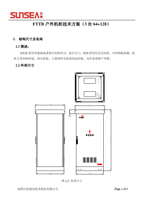
该机柜采用单舱落地或架空结构形式,前后开门,机柜采用夹芯层结构,中间垫隔热棉,机柜主体结构焊接,部分拼装,主要材料为优质热浸锌板,内外表面喷户外粉。
1.2外形尺寸
图1-2 外形尺寸
1.3内部布局
主设备舱宽度满足19英寸标准机框安装要求,其安装立柱高度为23U,设备安装空间为14U;
蓄电池位于设备舱底部,可提供4个大小为257(长)x176(宽)x166(高)的50AH蓄电池。
MDF最大安装容量为600外线模块,768内线模块;
主设备舱设备布局,如图1-2所示;
图1-2 设备布局
2.配置表
序号 存货编号
(料号)
名 称 规格
单
位
数
量
备注
1 柜体
高*宽*深
1550mmX750mmX750mm
set 1
1、含光缆固定板、接地铜排等
2、机柜材料热浸锌钢板
2 主设备舱风扇组件 含4个直流风扇、温控器set 1
3 交流防雷配电单元 C级防雷,交流1路32A
输入,1路20A输出, 6
路10A输出,3U高
set 1
4 蓄电池 12V/50Ah set 4
5 电源系统 GP4860,-48V/40A set 1
6 电源排插模块 set 1
7 保安接线排 25回线 set24
8 测试接线排 32回线 set32
9 保安单元 set600
10 XD-B1打线刀 set 1
11 19英寸12口光纤配线
盒 GC-BS-P1FC
set 1。
机柜说明_精品文档
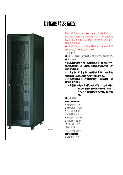
机柜图片及配置SYJS-01 机柜: 结合IBM*HP.*APC.*DELL等高档机柜的优点, 齐全的机柜设备管理附件, 兼具良好的通风效果, 外观高贵典雅, 工艺精湛、尺寸精密, 适用于各种高档办公环境。
●全部选用SPCC优质冷轧钢板制作;42U机柜厚度: 安装梁2.0mm,主体1.5 mm表面处理:●脱脂、酸洗、防锈磷化、纯水清洗、静电喷塑。
●性能特点:1外观设计高贵典雅: 高密度网孔前门和后门一并解决机械保护、通风散热、外部观察运行状态三方面的使用要求。
2工艺精湛、尺寸精密;可关闭的上部、下部多处走线通道, 底部大走线孔尺寸可按需调整。
3可选配安装底座, 达到固定机柜、底部过线、底部送冷风的要求;4可方便拆卸的左右侧门和前后门, 全方位操作,多方位察看;高效坚固的并柜连接。
5可同时安装脚轮和支撑脚;结构坚固;●机柜配置:600*2000*10001固定层板三个2四个高速排风扇3一个多位电源4支撑地角4只5万向转动轮4只6按装螺母40套7网孔前门1个,网孔后门1个,可拆卸侧门两个600*2000*6001固定层板三个机柜报价如下:600宽*2000高*1000深4100元(含税)600宽*2000高*600深3200元(含税)2二个高速排风扇3一个多位电源4支撑地角4只5万向转动轮4只6按装螺母40套7网孔前门1个, 网孔后门1个, 可拆卸侧门两个机柜图片及配置SYJS-01 机柜:●全部选用SPCC优质冷轧钢板制作;42U机柜厚度: 安装梁 1.5mm,主体1.0 mm表面处理:●脱脂、酸洗、防锈磷化、纯水清洗、静电喷塑。
●性能特点:1外观设计高贵典雅: 前门玻璃, 金属后门, 一并解决机械保护、通风散热、外部观察运行状态三方面的使用要求。
2工艺精湛、尺寸精密;可关闭的上部、下部多处走线通道, 底部大走线孔尺寸可按需调整。
3可选配安装底座, 达到固定机柜、底部过线、底部送冷风的要求;4可方便拆卸的左右侧门和前后门, 全方位操作,多方位察看;高效坚固的并柜连接。
机柜技术说明书

ZPX-415型违法闯红灯抓拍系统技术说明书编制:___________审核:___________工艺:___________标准化:___________批准:___________哈尔滨新中新猎豹电子工程有限公司目录一、概述: (1)二、结构特征 (1)三、安装和调试 (1)1、工控机单元安装调试技术要求: (1)2、工控机检验技术要求: (3)3、工控机箱检验技术要求: (5)4、机柜排风风扇安装技术要求: (5)5、机柜检验技术要求: (5)6、摄像机检验技术要求: (6)7、防护罩检验技术要求: (6)8、闪光灯检验技术要求: (6)四、整机检验技术要求: (6)五、硬件狗驱动板整机检验技术要求: (8)六、并口检测板检验技术要求 (9)七、红灯检测技术要求 (11)八、显示板检测技术要求 (11)九、温控板检测技术要求 (12)十、闪灯驱动板检验技术要求 (13)十一、故障分析与排除 (14)十二、维修和保养 (14)十三、产品成套器材 (14)一、概述:本说明书用于指导制造过程中的安装、调试、检验以及包装、存储等事项。
本说明书中未提及的与制造有关的其它部分,按常规方法和要求进行。
二、结构特征ZPX-415型违法闯红灯抓拍系统总体结构可分为主机部分和前端部分。
前端部分包括闪光灯组件和摄像机组件,主机部分包括防护机柜、工控机、检测控制单元、温控单元、闪光灯驱动单元、面板显示单元等,通过扁平连接线缆和导线相连接。
闪光灯组件由防护罩、闪光灯组成。
闪光灯组件的数量是根据抓拍的总车道数量确定的,即每个车道对应1个闪光灯组件。
摄像机组件由摄像机、摄像机防护罩、安装支架、开关电源等组成,它与抓拍主机的摄像机电源输出端子和工控机的视频输入端子相连接;它的数量由抓拍的方向数和车道数来确定。
闪光灯组件和摄像机组件单独包装。
三、安装和调试1、工控机单元安装调试技术要求:1、参照样机明确要装配的主板、并口、视频卡、电子盘和数据硬盘的位置,如图。
机柜空调使用说明书(RA-900W电子版)

图三
冷气机
电 控 箱
冷气机
图四
电控箱
错误
正确
-2-
错误
正确
泠逸工业制冷·安装使用说明书
机柜空调
2、安装方法 (1)当机组在搬运、装卸时,请始终保持设备处于垂直直立状态,不要将设备长期放在露天场所; (2)为使空调器的冷却效果最佳,请将机组直接安装在电气柜的外壁上或顶上(根据用户所选机型来决定), 请勿采用风管的形式进行送风,如若确实需要采用风管送风,请先咨询本公司技术工程师; (3)空调器在安装之前,请先确认好安装位置的强度是否能承载机组,以免造成人员受伤及设备损坏,当 安装在电气柜门上时,最好该扇箱门能固定不动,当需要打开时请先确认好加在门上的重量不会使整个电 气柜倾倒; (4)电气柜上必须开孔,以便使冷风能进入电控箱内,具体的开口尺寸请参见图五; (5)箱体开孔时请严格参照开口尺寸进行,孔口处的毛刺必须清除,以免划伤机组; (6)当长期使用时请注意安装螺栓是否损坏或脱落,若有而未加处理,将有可能导致机器掉落而损坏; (7)侧装式机柜空调的安装方式见下页图; (8)RA-900W 机柜空调安装开孔图见附页图纸;
-6-
泠逸工业制冷·安装使用说明书
机柜空调
菜单设置选项 回差设定 压缩机延时 温度设置下限 温度设置上限 模式选择 温度校正
户外机柜IPX55指导书

户外机柜IPX55指导书一、操作指导概述户外型机柜防水要求达到IPX5标准.所参照的标准为IEC60529-1989。
本指导书适用于户外型机柜的通用防水测试操作指导。
二、操作指导说明1测试条件1.1 环境条件:环境温度15-35℃,一个大气压。
1.2 场地:测试可在室内喷淋间操作或在室外操作。
2测试标准按IEC60529-1989标准中IPX5进行测试。
3测试设备3.1 水源:水质要求达到普通洁净自来水标准.喷淋房循环使用的水源需配备有过滤、净化措施. PH值应为6.5~7.2,电阻率不低于500Ω·m,水温与试验样品的温差不大于5℃3.2 喷嘴:IP55标准喷嘴.喷头要求参见IEC60529-1989.直径6.3MM3.3 流量计:流量要求12.5L/min+/-5%3.4 压力计:量程在100Kpa左右,能够准确读出25Kpa~35Kpa备注:或采用等同于IP55标准规定,而且经过华为认证的自动喷淋设备4测试要求4.1 测试工件要求:4.1.1待测机柜内部已完成装配,经过清洁,无水渍;4.1.2机柜作防水测试时不需加电;4.1.3每台机柜均需要测试。
4.2 测试参数,根据IEC60529-1989中IP55等级相关要求,淋水测试技术参数整理如下表:4压力计量程精度5Kpa,可调水压:25Kpa~35Kpa扇区区,见图一水柱垂直喷射高度来是通过流量或者是压力换算的直观确认方法5 水柱喷射高度水柱高度2.5m~3.5m之间为宜图二。
6 机顶测试角度机柜顶面与水柱夹角水柱与机顶夹角控制在45º~135 º,见图三。
通过工装、夹具调整机柜测试面、缝隙等测试单元与水柱之间的夹角满足要求,并保证一致性。
夹角定义见示意图7 其它测试角度水柱与其它测试面之间的夹角1、水柱与顶面以外其它面之间夹角满足60 º~120 º扇面内进行;见图四。
2、水柱方向与缝隙方向之间夹角在45º~135 º扇面内进行,见图五。
SRN系列电子开关柜产品说明书

SRN10630K SRN12630K SRN12830K SRN6625K SRN8625K SRN8630K SRN8830KProduct note SR2 seriesMetal enclosures for automation and distributionThe range of SR2 enclosures is a complete offer of monobloc metal enclosures for constructing small and medium-sized electric switchboards, in particular for control and command or small distribution: their typical use is as an on-board machine switchboard, thermal power station switchboard, pump control switchboard, and others.Construction characteristicsThe construction characteristics of the series guarantee practicalinstallation and versatility, as well as highly technical features, such as the IP65 degree of protection.The enclosure structure is fitted with two ample cable entry flanges (one for the top and one for the bottom side) so that the whole enclo-sure is made reversible, offering the possibility of having door opening either on the right or left.The apparatus can be installed either on a blind or slotted back plate or on a DIN rail combined with the various hinged modular panels.RangeThe range is available in two versions with blind or glass door and is divided into 23 different dimensions: from H=300 to 1200 mm, W=200 to 800 mm and D=150 to 300 mm.Some dimensions can also be stacked vertically, allowing two switch-board sections completely separate from each other to be made inside a single structure.The enclosures can by installed either on the wall using special brack-ets, or on the floor using a plinth h=100 mm.All the products in the range conform to the national and international standards in force, and in particular with the CEI EN 61439-1 and 2 Standard and have IP65 and TYPE 12 (UL Standard) degree ofprotection. The mechanical impact rating is IK10 for the version with blind door and IK09 for the version with glass door.Technical characteristicsConformity with CEI EN 62208, CEI EN 60439-1, IEC61439-1-2Degree of protection IP65 (CEI EN 60529) - TYPE 12 (Normativa UL)Mechanical impact rating IK10 blind doorIK09 glass door(IEC 62262)CertificationsII 3 G DType of metal material Installation site indoor Fixing methodwall/floorNormal service conditions - ambient temperature from –5 to +40 °CAtmospheric conditions - relative humidity50% at 40 °C 90% at 20 °CFor further information, please consult the “General Catalogue. Switchboards for automation” technical catalogue (cod. 1STC804013D0902).SR2 seriesMetal enclosures for automation and distribution Selection tableSR2 Enclosures | ABBSR2 Enclosures | ABBSR2 seriesMetal enclosures for automation and distributionNeutral or earthing busbarsThe busbars, made of electrolytic copper with M6 threaded holes with 25 mm pitch, can be mounted on the back plates by means of special supports. They must be sized according to the enclosure and their installation position.Sections for accessoriesThese allow accessories to be fixed (e.g. wiring ducts) inside the blind doors.They consist of a pair of white galvanized sheet vertical crosspieces15/10 thick pre-drilled with 25 mm pitch. In the 1000 and 1200 mm high enclosures with blind door, the sections are already provided.Code Description Dimensions mm (W)Adhesive label holderCode DescriptionDimensions mm (W)Diagram pocketsMade of plastic, grey RAL 7035 colour, size A4. The pocket can be applied inside the blind doors with width higher than 400 mm, by means of the adhesive provided.Code DescriptionLabelsCode DescriptionClosing caps for instrument panelsCode DescriptionDIN rail and fixing bracketsCode DescriptionDimensions mm (W)(2)Labels writable using compatible Grafoplast systemAccessoriesSR2 Enclosures | ABBOverall dimensionsSRN3215K SRN3315K SRN3415K SRN4315K SRN4320K SRN4420K SRN4620K SRN5320K SRN5420K SRN5425K SRN6420K SRN6425K SRN6625K SRN7520K SRN7525K SRN8625K SRN8630K SRN8830K30330330340340340340350350350360360360370370380380380320330340330330340360330340340340340360350350360360380314714714714719719719719719724719724724719724724729729782828282132132132132132182132182182132182182232232133,5133,5133,5133,5183,5183,5183,5183,5183,5233,5183,5233,5233,5183,5233,5233,5283,5283,5AB C D E 151,5151,5151,5201,5201,5201,5201,5251,5251,5251,5100100100100100150150150F (*)SRN10625K SRN10630K SRN10830K SRN12630K SRN12830K SRN5420VK SRN5425VK SRN6420VK SRN6425VK SRN7520VK SRN7525VK SRN8625VK SRN8630VKSRN10625VK SRN10630VK SRN10830VK SRN12630VK SRN12830VK 1003100310031203120350350360360370370380380310031003100312031203603603803603803403403403403503503603603603603803603803247297297297297197247197247197247247297247297297297297182232232232232132182132182132182182232182232232232232233,5283,5283,5283,5283,5183,5233,5183,5233,5183,5233,5233,5283,5233,5283,5283,5283,5283,5AB C D E 150150150150150150150150150150150150150150150150150150F (*)GHI L 237337437337337437637337437437437437637537537637637837G H I L 63763783763783743743743743753753763763763763783763783726326326336336336336346346346356356356366366376376376396396396311631163463463563563663663763763963963963116311631632633632632633635632633633633633635634634635635637635635637635637633633633633634634635635635635637635637633373373374374374374375375375376376376377377378378378371037103710371237123753753763763773773783783710371037103712371237(*)Locks (F)n o 1 central for enclosures with h=303 to 503 mm n o 2 for enclosures withh=603 to 703 mm (F=100 mm) n o 2 for enclosures from h=803 to 1203 mm (F=150 mm)(**)Coppered pinonly for enclosures from h=1003 to 1203 mm(***)Coppered pin on the doorn o 1 for enclosures from h=303 to 503 mm n o 4 for enclosures from h=603 to 803 mm n o 6 for enclosures from h=1003 to 1203 mm (****)Flange fixing holesn o 4 for enclosures from W=203 mmn o 6 for enclosures from W=303 to 403 mm n o 8 for enclosures from W=503 to 1203 mmPF3020PF3030PF3040 - PF4030PF4040PF5030PF5040PF6040 - PF4060PF6060PF7050PF8060PF8080PF1060PF1080PF1260PF1280Code O P 16026036036026036036056046056076056076056076026026026036046046056056066076076096096011601160Internal plates * The counterdoors with H 500 mm, 600 mm,700 mm, only have a centre hole for the lockKC5040K*KC6040K*KC7050K*KC8060K KC1060K KC1080K KC1260K KC1280KCode45655665675695695611561156M 360360460560560760560760NInternal counterdoors Modular panels and internal counte rdoor Front view1S T C 804017L 0201 - 12/2010 - 5.000Contact usABB SACEA division of ABB S.p.A.Automation and Distribuition Boards Via Italia, 5823846 Garbagnate Monastero (LC) - Italy Tel.: +39 031 3570 1 Fax: +39 031 3570228 The data and illustrations are not binding. We reserve the right to modify the contents of this document on the basis of technical development of the products, without prior notice.Copyright 2010 ABB. All rights reserved.SRN10630K SRN12630K SRN12830K SRN6625K SRN8625K SRN8630K SRN8830K。
40U-P 机柜现场准备指南说明书

Site Preparation Guide40U-P CabinetSite Preparation GuideRev. 04June 2020This Site Preparation Guide contains information about the 40U-P cabinet. Topics include:•About this guide (2)•Tools required (2)•Environmental requirements (2)•Air quality requirements (2)•Fire suppressant disclaimer (3)•Shock and Vibration (3)•Cabinet Clearance (4)•Cabinet stabilizing (4)•Site floor load-bearing requirements (5)•Casters and leveling feet (6)•Power requirements (7)•Package dimension and clearance (9)•Your next step (10)•If you need help (10)About this guideThis document includes information on:•Environmental requirements○Temperature○Weight○Altitude○Air Quality•Shock and vibration•Cabinet clearance•Cabinet stabilizing•Site floor load-bearing requirements•Casters and leveling feet•Power requirements•Package dimensions and clearanceThe illustrations in this guide are examples only. Depending on what your ordered, your configuration may lookTools required•Scissors•Mechanical Lift or Pallet JackEnvironmental requirements•+15°C to +32°C (59°F to 89.6°F) site temperature.*A fully configured cabinet (with six 30A single-phase line cords) may produce up to 49,100 BTUs per hour. Calculate the BTUs for yourconfiguration at •40% to 55% relative humidity*•The 40U-P weighs 198 KG (435); a cabinet fully configured with EMC products can weigh approximately 1,182 kg (2600 pounds).Make sure your flooring can safely support your configuration. Calculate the minimum load-bearing requirements for your site using the product-specific weights for your system components at •0 to 2439 meters (0 to 8,000 feet) above sea level operating altitude*•LAN and telephone connections for remote service and system operation* Recommended operating parameters. Contents of the cabinet may be qualified outside these limits; refer to the product-specific documentation for system specifications.Air quality requirementsThe products are designed to be consistent with the requirements of the American Society of Heating, Refrigeration and Air Conditioning Engineers (ASHRAE) Environmental Standard Handbook and the most current revision of Thermal Guidelines for Data Processing Environments, Second Edition, ASHRAE 2009b.Cabinets are best suited for Class 1 datacom environments, which consist of tightly controlled environmental parameters, including temperature, dew point, relative humidity and air quality. These facilities house mission-critical equipment and are typically fault-tolerant, including the air conditioners.The data center should maintain a cleanliness level as identified in ISO 14664-1, class 8 for particulate dust and pollution control. The air entering the data center should be filtered with a MERV 11 filter or better. The air within the data center should be continuously filtered with a MERV 8 or better filtration system. In addition, efforts should be maintained to prevent conductive particles, such as zinc whiskers, from entering the facility.The allowable relative humidity level is 20 to 80% non condensing, however, the recommended operating environment range is 40 to 55%. For data centers with gaseous contamination, such as high sulfur content, lower temperatures and humidity are recommended to minimize the risk of hardware corrosion and degradation. In general, the humidity fluctuations within the data center should be minimized. It is also recommended that the data center be positively pressured and have air curtains on entry ways to prevent outside air contaminants and humidity from entering the facility.2For facilities below 40% relative humidity, it is recommended to use grounding straps when contacting the equipment to avoid the risk of Electrostatic discharge (ESD), which can harm electronic equipment.As part of an ongoing monitoring process for the corrosiveness of the environment, it is recommended to place copper and silver coupons (per ISA 71.04-1985, Section 6.1 Reactivity), in airstreams representative of those in the data center. The monthly reactivity rate of the coupons should be less than 300 Angstroms. When monitored reactivity rate is exceeded, the coupon should be analyzed for material species and a corrective mitigation process put in place.Storage time (unpowered) recommendation: do not exceed 6 consecutive months of unpowered storage.Fire suppressant disclaimerFire prevention equipment in the computer room should always be installed as an added safety measure. A fire suppression system is the responsibility of the customer. When selecting appropriate fire suppression equipment and agents for the data center, choose carefully. An insurance underwriter, local fire marshal, and local building inspector are all parties that you should consult during the selection a fire suppression system that provides the correct level of coverage and protection.Equipment is designed and manufactured to internal and external standards that require certain environments for reliable operation. We do not make compatibility claims of any kind nor do we provide recommendations on fire suppression systems. It is not recommended to position storage equipment directly in the path of high pressure gas discharge streams or loud fire sirens so as to minimize the forces and vibration adverse to system integrity.The previous information is provided on an “as is” basis and provides no representations, warranties, guarantees orShock and VibrationProducts have been tested to withstand the shock and random vibration levels. The levels apply to all three axes and should be measured with an accelerometer on the equipment enclosures within the cabinet and shall not exceed:Platform condition Response measurement levelNon operational shock10 G’s, 7 ms durationOperational shock 3 G’s, 11 ms durationNon operational random vibration0.40 Grms, 5–500 Hz, 30 minutesOperational random vibration0.21 Grms, 5–500 Hz, 10 minutesSystems that are mounted on an approved package have completed transportation testing to withstand the following shock and vibrations in the vertical direction only and shall not exceed:Packaged system condition Response measurement levelTransportation shock10 G’s, 12ms durationTransportation random vibration• 1.15 Grms• 1 hour Frequency range 1–200 Hz3Cabinet ClearanceThis cabinet ventilates from front to back; you must provide adequate clearance to service and cool the system. Depending on component-specific connections within the cabinet,15-foot extension power cords are required.Figure 1. Cabinet ClearanceThe illustrations in this guide are examples only. Depending on what your ordered, your cabinet may look somewhatCabinet stabilizingIf you intend to secure the optional stabilizer brackets to your site floor, prepare the location for the mounting bolts. (The additional brackets help to prevent the cabinet from tipping while you service cantilevered levels, or from rolling during minor seismic events.) The brackets provide three levels of protection for stabilizing the unit:•Anti-tip bracket - Use this bracket to provide an extra measure of anti-tip security. One or two kits may be used. For cabinets with components that slide, we recommend that you use two kits.All measurements are in inches.EMC2853•Anti-move bracket - Use this bracket to permanently fasten the unit to the floor.4Seismic restraint bracket - Use this bracket to provide the highest protection from moving or tipping.•All measurements are in inches.EMC2856Site floor load-bearing requirementsInstall the cabinet in raised or non-raised floor environments capable of supporting at least 1,180kg (2,600 lbs.) per cabinet. Your system may weigh less, but requires extra floor support margin to accommodate equipment upgrades and/or reconfiguration.In a raised floor environment:•24 x 24 inch or (60 x 60 cm) heavy-duty, concrete filled steel floor tiles are recommended.•Use only floor tiles and stringers rated to withstand:○concentrated loads of two casters or leveling feet, each weighing up to 1,000 lb (454 kg).○minimum static ultimate load of 3,000 lb (1,361 kg).○rolling loads of 1,000 (454) kg). On floor tiles that do not meet the 1,000 lb rolling load rating, use coverings such a plywood to protect floors during system roll.•Position adjacent cabinets with no more than two casters or leveling feet on a single floor tile.5•Cutouts in 24 x 24 in tiles must be no more that 8 inches (20.3 cm) wide by 6 inches (15.3 cm) deep, and centered on the tiles, 9inches (22.9 cm) from the front and rear and 8 inches (20.3 cm) from the sides. Since cutouts will weaken the tile, you can minimize deflection by adding pedestal mounts adjacent to the cutout; the number and placement of additional pedestal mounts relative to a cutout must be in accordance with the floor tile manufacture's recommendations.When positioning the cabinet, take care to avoid moving a caster into a floor tile cutout.Ensure that the combined weight of any other objects in the data center does not compromise the structural integrity of the raised floor and/or the subfloor (non-raised floor).We recommend that a certified data center design consultant inspect your site to ensure that the floor is capable of supporting thesystem and surrounding weight . Note that actual cabinet weight depends on your specific product configuration; you can calculate your total using the tools available at Casters and leveling feetThe cabinet bottom includes four caster wheels. The front wheels are fixed; the two rear casters swivel in a 1.75-inch diameter. Swivel position of the caster wheels will determine the load-bearing points on your site floor, but does not affect the cabinet footprint. Once youhave positioned, leveled, and stabilized the cabinet, the four leveling feet determine the final load-bearing points on your site floor.CL3627FrontRear viewRear viewNote: Some items in the views are removed for clarity.(see detail A)Dimension 3.620 to center of caster wheel from this surfaceDetail A(right front corner)1.750Caster swivel diameterDetail B Bottom view Leveling feetAll measurements are in inches.The customer is ultimately responsible for ensuring that the data center floor on which the system is to be configured is 6Power requirementsDepending on the cabinet configuration and input ac power source, single or three-phase, the cabinet requires two to 12 independent power sources. To determine your site requirements, use the published technical specifications and device rating labels. This will helpprovide the current draw of the devices in each rack. The total current draw for each rack can then be calculated. For Dell EMC products,visit the "Dell EMC Power Calculator" on the web at .Table 1. Single-phase power connection requirementsSpecificationNorth American3 wire connection (2 L and 1 G)aInternational and Australian 3 wire connection (1 L, 1 N, and 1 G)Input nominal voltage200 - 240 V ac +/- 10% L - L nom 220 - 240 V ac +/- 10% L - L nomFrequency 50 - 60 Hz 50 - 60 HzCircuit breakers 30 A 32 A Power zonesTwo TwoPower requirements at site (minimum to maximum)•One to six 30 A, single-phase drops per zone•Each rack requires a minimum of two drops to a maximum of 12 drops. This will bedetermined by the system configuration and the power needs for that configuration.a.L = line phase, N = neutral, G = groundTable 2. Single-phase AC power input connector optionsSingle-phase rack connector optionsCustomer AC source interface receptacleSiteNEMA L6-30P NEMA L6-30RNorth America and JapanRussellstoll 3750DPRussellstoll 9C33U0North America and JapanIEC-309 332P6IEC-309 332C6InternationalCLIPSAL 56PA332CLIPSAL 56CSC332AustraliaTable 3. Three-phase AC power connection requirementsSpecificationNorth American (Delta)4 wire connection (3 L and 1 G)aInternational and Australian (Wye)5 wire connection (3 L, 1 N, and 1 G)Input nominal voltage 200 - 240 V ac +/- 10% L - L nom 220 - 240 V ac +/- 10% L - N nom Frequency 50 - 60 Hz 50 - 60 Hz Circuit breakers50 A32 A7Table 3. Three-phase AC power connection requirements (continued)a.L = line phase, N = neutral, G = groundTable 4. Three-phase Delta-type AC power input connector optionsThree-phase Delta rack connector optionsCustomer AC source interface receptacleSiteRussellstoll 9P54U2Russellstoll 9C54U2North America and InternationalHubbell CS-8365CHubbell CS-8364CNorth AmericaTable 5. Three-phase Wye-type AC power input connector optionsThree-phase Wye rack connector options Customer AC source interface receptacleSite GARO P432-6GARO S432-6InternationalHubbell L22-30PHubbell L22-30RNorth AmericaFly Lead Customer Receptacle International8Table 5. Three-phase Wye-type AC power input connector options (continued)Three-phase Wye rack connector options Customer AC source interface receptacle SitePackage dimension and clearanceMake certain your doorways and elevators are wide enough and tall enough to accommodate the shipping pallet and cabinet. Use a mechanical lift or pallet jack to position the packaged cabinet in its final location.EMC28369Your next stepFollow the illustrated instructions printed on the outside of the shipping unit to remove the cardboard packing material; cut the shipping straps and corner tape, then remove the top cover and tape.Refer to the 40U-P Cabinet Unpacking and Setup Guide located on for instructions on:•attaching the unloading ramp,•releasing the cabinet from the pallet,•unloading the cabinet•setting up the cabinet in your environment, and•repackaging shipping material.If you need helpFor questions about technical support and service, contact you service provider.For questions about upgrades, contact your sales office.10Notes, cautions, and warningsA NOTE indicates important information that helps you make better use of your product.A CAUTION indicates either potential damage to hardware or loss of data and tells you how to avoid the problem.A WARNING indicates a potential for property damage, personal injury, or death.© 2018 - 2020 Dell Inc. or its subsidiaries. All rights reserved. Dell, EMC, and other trademarks are trademarks of Dell Inc. or its subsidiaries. Other trademarks may be trademarks of their respective owners.。
户外机柜的技术性能介绍
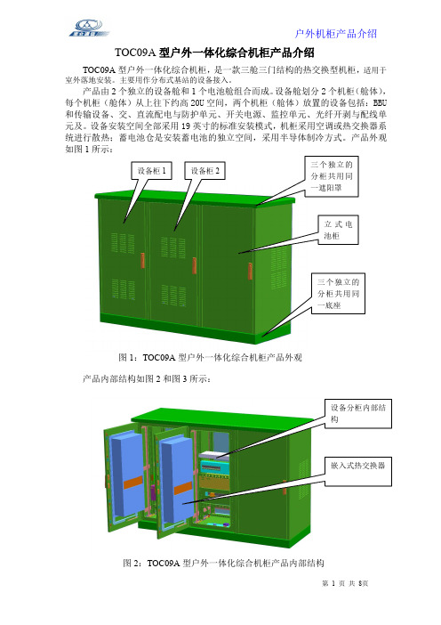
TOC09A 型户外一体化综合机柜产品介绍TOC09A 型户外一体化综合机柜,是一款三舱三门结构的热交换型机柜,适用于室外落地安装。
主要用作分布式基站的设备接入。
产品由2个独立的设备舱和1个电池舱组合而成。
设备舱划分2个机柜(舱体),每个机柜(舱体)从上往下约高20U 空间,两个机柜(舱体)放置的设备包括:BBU 和传输设备、交、直流配电与防护单元、开关电源、监控单元、光纤开剥与配线单元及。
设备安装空间全部采用19英寸的标准安装模式,机柜采用空调或热交换器系统进行散热;蓄电池仓是安装蓄电池的独立空间,采用半导体制冷方式。
产品外观如图1所示:图1:TOC09A型户外一体化综合机柜产品外观产品内部结构如图2和图3所示:图2:TOC09A 型户外一体化综合机柜产品内部结构图3:TOC09A型户外一体化综合机柜产品内部结构图1:TOC09-1350型机柜外观图2:TOC09-1350型机柜设备1舱内部设备图3:TOC09-1350型机柜设备2舱内部结构图4:TOC09-1350型机柜立式电池舱内部结构对于具有特别寒冷天气的地区(室外温度低于-10℃的地区),设备舱可选用带PTC 辅助加热功能的空调或热交换器。
当室外温度对于机柜内部设定的温度时,外循环风机和压缩机停止转动。
内循环风机启动,同时内部的PTC 加热器启动,给机柜内部升温。
确保机柜内部在设定的温度范围之内。
PTC 加热器也可选择单独的PTC辅助加热模块,安装在机柜内部,该模块采用标准19英寸安装,安装灵活。
加热模块由安装在机柜内部的温控器控制。
低于设定的温度,加热器启动。
高于设定的温度,电源断开,加热器停止工作。
(由于PTC加热器加热的高温度为75℃左右。
所以非常安全)。
PTC辅助加热模块可根据要求配置动力与环境监控单元,能通过基站动力环境集中监控系统将机柜里电源掉电、电源故障、门禁、温度、湿度、烟雾、水浸、蓄电池电压等告警量上报到OMC。
我公司的机柜监控单元的外观及监控功能如下图所示:。
- 1、下载文档前请自行甄别文档内容的完整性,平台不提供额外的编辑、内容补充、找答案等附加服务。
- 2、"仅部分预览"的文档,不可在线预览部分如存在完整性等问题,可反馈申请退款(可完整预览的文档不适用该条件!)。
- 3、如文档侵犯您的权益,请联系客服反馈,我们会尽快为您处理(人工客服工作时间:9:00-18:30)。
WF(G)-11
室外机柜
产
品
说
明
书
感谢购买本公司的产品,在您安装使用之前请认真阅读本说明书!
1、概述
WF(G)-11型通信用室外机柜是一种适用于户外的综合型接入网设备。
可满足宽带及交换机设备的安装(选配);电源的接驳;通信配线线路的成端;光、电线缆的进出;门禁的监控,并可提供门禁开关告警信号,具有良好的防盗性能;采用风扇强制制冷技术以及隔热保温设计,对室外机柜实现可靠的温度管理,确保柜内通信设备在高温和高寒等恶劣环境下的安全运行。
在户外安装条件下,可以抵御风沙、雨水、阳光的辐射的影响。
本设备由设备柜,蓄电池柜,风扇等组成。
2、机柜外形尺寸(见下图)
3.产品的特点及功能
3.1 柜体采用优质不锈钢做主材, 具有良好的机械及防腐性能,耐候性优良。
3.2 表面喷涂防紫外线粉末,双层隔热设计。
强度高,外型美观;
3.3 标准19英寸安装方式,配置灵活;
3.4 全正面化操作,节省机房空间;
3.5 强弱电分开,有专门的走线槽,进缆跳线全正面化操作;
3.6 有足够的光纤盘储空间,保证光缆、光纤的曲率半径;
3.7 可靠完善的接地保护。
3.8 所有技术性能指标均符合GB4208-1993外壳防护等级IP55级.
4.环境要求
4.1 工作温度:-45℃~+55℃相对湿度:≤95%(+30℃)大气压力:70KPa~106Kpa 4.2 主要技术指标
4.2.1 机柜部分
◇机柜高压防护地与机柜绝缘,绝缘电阻>1000MV/500VDC
◇机柜防护地与机柜间耐压>3000VDC/min不击穿,无飞弧
5、设备的安装.
户外机柜须安装在水泥基座或其它坚固可靠的基座上。
5.1水泥基座示意图(见下图)
电池仓
设备仓
5.2机柜门的操作
本设备的门锁采用专用钥匙进行的门的开启与锁闭。
开锁时,将锁盖板旋转开,将专用钥匙对入锁孔的凹槽,插入后向右旋转约75度,弹出锁体的把手,向右旋转把手,即可打开机柜门。
锁闭时,将把手向左旋转,对准把手槽压进槽内,拔出钥匙即可。
5.3 电缆、光缆的引入
5.3.1 先将两条垫木(10cm高左右)放在水泥台上,再将机柜放在垫木上,然后将电缆、光缆从
水泥缆孔中穿出。
5.3.2 打开机柜底部进缆孔位,将需引入到机柜内的电缆、光缆从底部线缆孔通过密封圈引入到
机柜内,并在机柜内留足余长。
5.3.3 抽出垫木,将水泥台上预留膨胀螺柱套入机柜安装孔内,用螺母、弹、平垫将机柜固定5.3.4 电缆引入后,请用附件中的防水密封胶将缆孔堵死。
电缆、光缆沿走线槽分开有序分布,用扎带扎好.顶部用粘片导引线路.设备用卡式螺丝安装.
6.机柜的维护与保养
6.1、户外机柜必须有专人进行周期性的巡检与清洁维护。
防止昆虫和灰尘在箱体内堆积,保持箱体
的干净。
6.2、机柜空调的维护:机柜空调在比较恶劣的室外环境下运行,为了保障空调器的正常运行,请参
考表1对空调器进行定期维护。
警告:所有的维护工作必须由合格的专业人员进行维护,在进行任何维护前,请事先断开空调器电源和信号线,维护工作结束后接通空调器电源和信号线。
维护工具列表:
1.吸尘器或者压缩空气。
2.软毛刷。
3.十字螺丝刀。
为了保持机柜的正常温度环境,请根据表1进行维护。
维护步骤:
1.关闭电源。
2.断开电源线,断开信号线。
3.按检查表进行日常维护。
4.接驳电源线,信号线。
5.进行测试程序。
6.断开电源,恢复机组运行正常状态。
7.闭合电源。
7.设备包装、运输、贮存
6.1 包装:本机包装按产品包装规范包装,具有防潮、防震措施,附件、备用件另装袋后再装入包装箱,整机用塑料膜加纸(木)箱包封.
6.2 运输:本机可适应各种交通工具的运输,经包装的产品在运输过程中,要求环境温度在-30℃~55℃之间,相对湿度不大于90%。
在30℃以上应有遮蓬,产品不能雨淋、浸泡、日光暴晒。
装卸和搬运应按包装上刷制的运输作业标志进行,不准将产品倒放、侧放和翻转。
6.3 贮存:箱子上方不应堆积过重物品,库房内空气中酸性、碱性或其它有害气体应符合环保规定的要求。
室内温度为-5℃~45℃之间,相对湿度不大于75%的范围内
8.备附件清单。