PARKER 气缸的样本
派克P1A系列气缸商品说明书
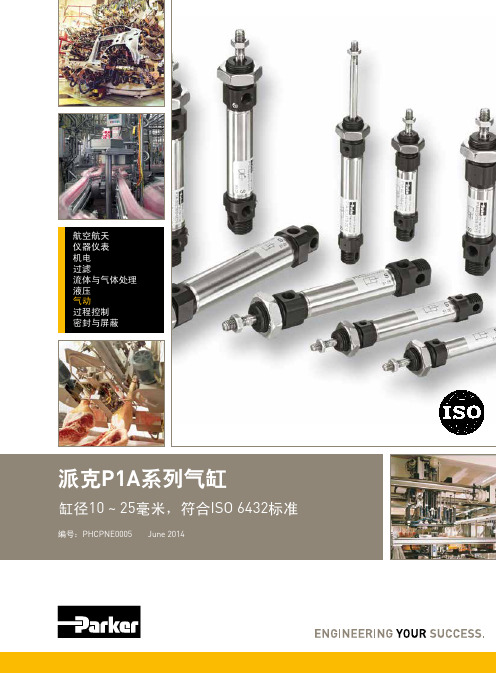
航空航天仪器仪表机电过滤流体与气体处理液压气动过程控制密封与屏蔽2Parker Hannifin Corporation Pneumatic Division - EuropePHCPNE0005P1A 气缸特点气缸 液压缸 电动缸负载安全 *** *** *负载大小 *** *** *速度变化 *** *** *速度 *** ** **可靠性 *** *** ***坚固 *** *** *安装成本 *** * **维修成本*** ** *潮湿环境下的安全性 *** *** *爆炸环境下的安全性 *** *** *电气装置的安全风险 *** *** *抗漏油的风险 *** * ***清洁卫生 *** ** *尺寸标准化 *** *** *使用寿命*** *** *需要液压系统配合 *** * ***重量 ** ** **采购价格 *** ** *功率密度 ** *** *产生噪音 ** *** **推力尺寸比 ** *** *定位 * *** ***能量消耗 * ** ***保养周期 * ** ***需要压缩机 * *** **** = 好,**=中等,***=优秀3Parker Hannifin Corporation Pneumatic Division - EuropePHCPNE0005P1A 气缸内容 页码ISO 气缸系列,P1A ........................................................................................4-5气缸作用力 .........................................................................................................6主要参数.............................................................................................................7工作介质,空气质量 ..........................................................................................7材料参数.............................................................................................................8缓冲性能.............................................................................................................8尺寸 ....................................................................................................................9选择合适的管路..........................................................................................10-11订购代码...........................................................................................................12标准行程...........................................................................................................12P1A 单作用气缸订购指南..................................................................................13P1A 双作用气缸订购指南............................................................................14-15P1A 气缸导杆 ..............................................................................................16-18气缸附件.....................................................................................................19-22传感器 ........................................................................................................23-26带一个插头的电缆 ............................................................................................27电缆连接的公接头 .. (27)4Parker Hannifin Corporation Pneumatic Division - EuropePHCPNE0005P1A 气缸双作用和单作用气缸P1A 系列气缸的设计使其适用广泛的应用场合。
朗克公司气缸系列产品指南说明书

The Right Cylinder for the Right DutyContentsIntroduction (2)Hydraulic vs. Pneumatic (2)Design Factors (2)Capacity (3)Stroking Distance (3)Speed (3)Temperature (3)Mounting Styles (4)Cylinder Bore Size (4)Piston Rod Size (4)Cylinder Configurations (5)Rod Ends / Rod Threading (5)Cylinder Body Tube (5)Stop Tubing (5)Seals (5)Additional Considerations (5)Conclusion ..................................................................................................6About the AuthorsJim Hauser is a Senior Engineer who started his career as an Engineer Trainee at Parker Hannifin Cylinder Division 43 years ago. Throughouthis tenure, he has held positions as a Design Engineer, Lab Supervisor and most recently Quote Engineering. He has a BS in Mechanical Engineering from the Illinois Institute of Technology. Rade Knezevic has 24 years with Parker Hannifin and is currently a Global Account Manager. He holds a BSin Industrial Engineering, from the University of Illinois Urbana-Champaign and an MBA from Keller Graduate School of Management. Rade is responsible for the sales growth of Industrial and Mobile cylinders in the Eastern Region of the US, which includes management of six field-based Cylinder Application Engineers (CAEs). Rade started his career in Manufactur-ing Engineering as a Trainee and has held positions as a CAE, Product Manager and Division Business Development Manager.Jim Hauser Rade Knezevic Senior Engineer, Division Sales Manager, Parker Cylinder Division Parker Cylinder DivisionIntroductionThe first hydraulic press may have been invented in the 3rd Century BC, but the fluid power universe has become a little more compli-cated since then. Today’s hydraulic cylinders, which essentially convert fluid pressure and flow into force and linear movement, are complex devices incorporating a wide range of individual components available in a multitude of dimensions, configurations and materials. For many OEM design engineers, playing it safe by over-engineering cylinder specifications has become a precautionary habit in the presence of ever-improving cylinder technologies. This article will help clarify why less is sometimes more when it comes to complex hydraulic systems, while identifying some of the many factors to be considered when specifying hydraulic cylinders.Design Factors in Hydraulic Cylinder SpecificationSpecifying hydraulic cylindersis essentially a balancing act as each design factor influences one or more of the many other design considerations. For example, the urethane seals ideal for applications as cold as -65°F (-54°C) will tolerate 200°F (129°C) of heat, while other materials capable of tolerating temperatures as high as 500°F (260°C), will do so at the sacri-fice of some cold-temperature performance.Although NFPA standards and ISO-compliant guidelines are a great starting point for hydraulic system design, many industries have guidelines of their own. Working with an engineering manufacturer experienced with all these standards can expedite the design process.Cylinder manufacturers can offera range of options capable ofachieving the widest scope ofperformance requirements thatincrease the likelihood thatstandard components will meetthe design criteria of a application.For example, most cylinder man-ufacturers offer 19 mount options,which cover the standard NFPAmount offerings. Standard compo-nents have the additionaladvantage of being readilyavailable worldwide, expeditingjust-in-time warehousing anddelivery of replacement parts ascomponents reach the end oftheir service life cycle.A review of the major factors is tobe considered when specifyinghydraulic cylinders follows.Hydraulic vs. PneumaticAlthough pneumatic systems are in some respects simpler, they are generally incapable of achieving the transfer of higher loads and forces. Hydraulic cylin-ders also have the advantage of smoother, more controllable movement as they are devoid of the spring-like action associated with the release of gaseous fluid media. As an added benefit, hydraulic systems can perform ancillary functions such as lubricating and cooling.However, since the availability ofpower and media is a non-nego-tiable factor in fluid powersystem design, it should benoted that a properly designedand sized pneumatic system canachieve higher performancewhere a compact footprint is notrequired. Further considerationsof pneumatic cylinder design areoutside the scope of this article.Although NFPA standards and ISO-compliant guidelines are a great starting point for hydraulic system design,many industries have guidelines of their own. “”CapacityMedium-duty systems account for most of industrial applications and are typically at 1000 PSI. Heavy-duty systems are com-mon to applications such as hydraulic presses, automotive applications, and other related industrial applications. Standard heavy-duty hydraulic cylindersare capable of handling pres-sures as high as 3000 PSI, withload capabilities relative to thefull piston area (in square inches)when exposed to fluid pressuremultiplied by the gauge pressurein PSI. Excessive load require-ments may be achieved withoutsacrificing other areas of perfor-mance through the use oftandem cylinder constructionsrather than larger bore or customhigh-pressure cylinder designs.Stroking Distance RequirementsAlthough custom stroke distanc-es above 10 feet (3.05m) are possible. Pressure rating can be a concern. Rod diameter needs to be determined to handle the load. If necessary, a pressurerating on load in thrust (pushmode) will need to be specified.Rod sag from horizontal applica-tions may result in premature rodbearing wear. Weighing eachpositive effect against potentialnegatives is essential to optimiz-ing hydraulic systemperformance.SpeedEvery application engineer has his or her own definition of “excessive speed.” As a good rule of thumb, standard hydraulic cylinder seals can easily handle speeds up to 3.28 feet (1 meter) per second. The tolerance threshold for standard cushions is roughly two thirds (2/3) of that speed. Frequently, a standard low-fric-tion seal is the better choice forhigher speed applications. Buthere too, what you gain in oneaspect of performance you losein another. The greater the fluidvelocity, the higher the fluidtemperature, so when opting forspeed-increasing customizationsit is essential to consider theimpact of higher temperatures onthe entire hydraulic system. Insome hydraulic systems, over-sized the ports may eliminateescalated temperature concerns.TemperatureAs previously noted, hydraulic cylinder systems using standard components can be designed to meet application temperatures as hot as 500°F (260°C) and as cold as -65°F (-54°C). But tempera-tures affect both the “hard” and “soft” design components of cylinders. Applications requiringtemperature extremes at eitheror both ends of the temperaturespectrum require extensiveknowledge of the interdependen-cy of individual components toachieve the best balance ofshort- and long-termperformance expectations. Forexample, applications near thenorth or south poles, will seecontraction of the seals andmetal parts due to the extremetemperatures.Mounting StylesThere are fundamentally three categories of mounting styles. Both Fixed and Pivot styles can absorb forces on the cylinder’s centerline and typically include medium- and heavy-duty mounts for accommodating thrust or tension. A third category of Fixed styles allows the entire cylinder to be supported by the mounting surface below cylinder centerline, rather than absorbing forces only along the centerline.There are several available standardized mounts within these categories. Engineers can use these variety of mount offerings for an ever-widening number of application require-ments. NFPA Tie rod cylinders, which are used in the majority of industrial systems, typically can be mounted using a variety of standard mating configurations from trunnion-style heads and caps to extended tie rod cap and/ or head end styles, flange-style heads, side-lug and side-tapped styles, a range of spherical bearing configurations, and cap fixed clevis designs. Most of these mounting options are available for both single acting and double rod cylinders.The goal of every mounting design is to allow the mount to absorb force, stabilizing the system and optimizing perfor-mance. For rods loaded primarilyin compression (push), cap endmounts are recommended; forthose in tension (pull), a headend mount is preferred.It is the amount of tension orcompression that determinespiston rod diameter; it is theamount of pull or push thatdetermines the bore diameter.Other relevant factors to considerwhen selecting a mounting styleinclude:• Load• Speed• Cylinder motion (straight/fixed or pivot)Every mounting type comes withits own benefits and limitations.For example, trunnions forpivot-mounted cylinders areincompatible with self-aligningbearings where the small bearingarea is positioned at a distancefrom the trunnions and cylinderheads. Improper use of such aconfiguration introduces bendingforces that can overstress thetrunnion pins.Many performance expectationsthat at first appear to requireatypical mounts can be accom-modated by existing styles,sometimes with only slightmodifications, facilitating replace-ment and reducing costs.Cylinder Bore SizeBore size is related to operating pressure; as previously noted, it is the amount of push or pull force required that determines the bore size needed. Earlier generations of steel and alumi-num mill equipment oftenrequired the use of non-standardbore and rod sizes. Today,virtually every industrial require-ment can be met with NFPAstandard and/or ISO-compliantcomponents.Style J(NFPA MF1)Style JB(NFPA MF5)Style H(NFPA MF2)Piston Rod Size OEM design engineers probablyrequest customization of piston rod sizes more frequently than any other hydraulic cylinder component. What is not always considered is the simple fact that push or pull is never independent of stroke length. Just as a pushed rope holds a straight line only in relation to its length (the longer the rope, the more the rope curls), piston rods under compression or tension tend to diffuse force in non-linear directions.Specifying costly materials such as stainless steel or alloy steels for the rods themselves is another common example of over-engi-neering. In most extreme applications, chrome plating provides a high level of corrosion-resistance required to optimize system longevity.Cylinder ConfigurationsFor applications requiring equal force pressure on both sides of the piston, a standard double-acting cylinder configuration using pressure to extend and retract the cylinder, combined with a four-way directional control valve to direct pressure to either the head or the end cap, is almost always preferable to more customized solutions. An experienced hydraulic solu-tions manufacturer will be familiar with every conceivable cylinder assembly configuration and the unintended consequences of customizing individual components versus combining standard cylinders in creative ways to meet unusual performance requirements.Rod Ends / RodThreadingThis is one area where standardoptions are so vast customizationis rarely needed. Additionally,standard threads can be made ininch or metric format. Typically,each available diameter isavailable in four distinct rod endstyles. Even in those rareinstances where a modificationseems to be called for, it isimportant to considerthe effects of modifications onfunction-enhancing accessories.The relatively small performancecompromise resulting fromstandardizing rod ends is almostalways warranted by the versatil-ity such standardization affords.Even a modest modificationsuch as under-sizing threads willrequire de-rating the cylinder andmay necessitate special toolingfor non-standard pitch, resultingin delays, expense, and theinability to readily mate withaccessory components.CylinderBody TubeStandard cylinder bodies areplain steel or chromed plated andwill be able to handle a majorityof applications. Using alloysteels, stainless steel or brassmaterials are prevalent in specialapplication like a water typeenvironment.Stop TubingStop tubing is generally used tolengthen the distance betweenthe rod bearing and the pistonbearing in order to reducebearing load on push-strokecylinders when the cylinder isfully extended. Stop tubing isespecially critical for horizontallymounted cylinders where it helpsto restrict the extended positionof the rod. In such applications,increased distance helps achievegreater stability and increasebearing life.SealsAlthough it is not common torequire all existing materialcompounds, an experiencedhydraulic system manufacturerwill offer seals to meet a com-plete range of temperatures andfluid types, and can help guidean engineer’s specification tomeet precise application require-ments.HY08-1731-B1 07/20© 2020 Parker Hannifin Corporation Parker Hannifin CorporationCylinder Division500 South Wolf RoadDes Plaines, IL 60016-3198 USA /cylinder ConclusionThere are certainly applications for which specifying the right cylinder for the right duty require some customization either in component size, material type or configuration. However, far more often than not, partnering with an experienced hydraulic system solution manufacturer early in the design process will save the OEM engineering team time and money while ensuring the system does its assigned duties as efficiently as possible for as long as possible.Additional Considerations Every industrial application is unique, and there are many ancillary components involved in hydraulic cylinder specification. Energy-absorbing cushions, pillow blocks, regenerative circuits, over- or under-sizing ports — all these and more contribute to optimizing the performance of hydraulic sys -tems, depending on each application’s specific perfor -mance requirements. As with the specification of more fundamental components, selecting appropriate ancillary components can present a specification challenge. For example, cushions are intended to retard the force of motion, but OEM engineers sometimes overlook the fact that fluids are typically not moving very fast anyway and may not require such redundancy in certain types of systems. An engineer may be tempted to take a “belt and suspenders” approach to design -ing push/pull systems by using cushions with spring cylinder systems, overlooking the fact that the oil needs to work its way through the cap, hoses, valves and so on. In such cases, specifying standard single action cylinders with cushions may be wiser than attempting to insert cushions into spring cylinders.New Automated Cylinder Quoting ToolNeed help determining the right cylinder for yourneeds? Use Parker’s easy to use cylinder quoting tool.。
PARKER油缸2H系列拉杆缸

派克汉尼汾是全球运动和控制技术行业的领导 者。派克在 1200 个工业和航空航天市场上,提供 800 多个液压、气动和机电产品系列。派克在全球拥有 50000 多名员工、210 个制造工厂和办公点,以能够给 客户提供卓越的技术和一流的服务而著称。
/
凸肩上的场合;当负载并非紧靠在活塞杆端凸肩
上时,推荐使用杆端方式 8。
杆端方式 9 当需要使用杆端内螺纹进行连接时,使用该
杆端方式。
杆端方式 3 方式 3 为非标的杆端方式的代号。订购时,
请附上杆端的图纸或文字说明,并须指明 KK 和 A 的尺寸。
杆端方式 7 方式 7 仅适用于活塞杆端装配带球面轴承的
的速度——见第 B35 页。缸头端的缓冲是自动对中 的,而表面抛光的缸盖端缓冲则是活塞杆的一部 分。
双唇防尘圈起第二道密封作用,能够把多余的润 滑油膜密封在防尘圈与唇形密封件之间的容腔内。其 外唇防止脏物进入缸内,从而延长了 Gland 和密封件 的使用寿命。
8 浮动的缓冲衬套和套筒 缸头端采用浮动的缓冲套筒,缸盖端则采用浮
除非另行注明,所有尺寸单位均为毫米。
1 除 1"-14 的螺纹按 UNS 标准外,其余螺纹按 UNF 标准。 2 方式 7 仅适用于杆端装配带球面轴承的耳环附件的场合,
见第 B29 页。
派克汉尼汾
B3
液压缸部
中国
样本 HY07-1110/CN 贮存、安装和重量
拉杆缸 2H 系列
贮存
当液压缸需要存放在干燥、干净和无腐蚀性气体的室内环境
2. 若液压缸的工作环境中存在可快速干燥的化 学制品、油漆、焊接飞溅物等,或者处于其他 具有危害性的环境中,如过高的温度,则必须 加装防护罩,以防止对液压缸的活塞杆和杆密 封件造成损害。
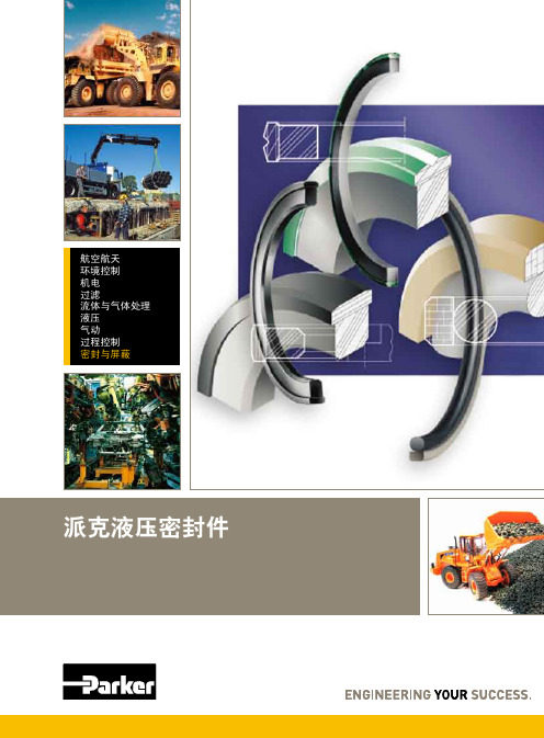
PARKER液压密封
本样本中的所有产品均由派克•汉尼汾公司及其子公司和授权经销商销售。与派克签订的任何销售合同均按照派克标准条件和销售条件中规定的条款执行(提供复印件备索)。
本公司的密封件,只能在本公司的文件资料述及的应用参数范围与接触介质、压力、温度和 存放时间相一致的情况下才能使用。 在规定的应用参数范围外使用以及错误选用不同的材料都可能导致密封件寿命的缩短以及设 备的损坏,甚至更严重的后果(如生命安全,环境污染等)。 本公司出版印刷的资料和数据集数十年制造和应用密封件之经验。尽管如此,在密封件实际 应用中出现的各种未知因素可能会极大地影响本资料的全面使用,故样本中提出的各种建议 仅供参考。客户必须分析您的具体应用,确认相关产品和系统,并承担一切责任。派克汉尼 汾公司虽尽力但仍不能保证本样本资料的准确性和完整性,因此用户要承担信任本资料的风 险。 本公司保留设计修改而不预先通知的权利。该版本替代所有以前的样本。 样品是从实验模具制得的。但是以后的系列产品可以采用与样品生产不同的生产技术,除非 事先达成特殊协议。 本公司所有产品的模具使用年限为7年,因此产品交付保证可能受此影响。
1,0
-30/+80
• • 3 RodSeals 16
1,0 -30/+80
1,0 -30/+80 AG A• G•• ...•..........-..........1.,.0.......-.3.5../+..1..1.0............... 22 (bar) m/s C E8 • �AG A•.H........................................S...t.a...n...g..e...n...d...i.c..h...t.u...n...g..e...n... ..2.5............ 5 6)...161 ,0 -30/+80
派克阀门样本Parker Valve

Female NPT thread (SAE 476) / Female NPT thread (SAE 476)
Visual index 3/2-way ball valves
KH 3/2 (S) p. O42
EO 24° cone end / EO 24° cone end / EO 24° cone end
KHBLOCK p. O51
Ball valve with Flange connection DIN EN 1092-1
2/2-way ball valve for block structure
O6
Catalogue 4100-8/UK
Visual index shut off valves and Line Rupture Valves “LRV”
DV p. O52
Valves
LD p. O53
EO 24° cone end / EO 24° cone end
VDHA p. O54
EO 24° cone end / EO 24° cone end
EO tube end / EO tube end
WV p. O55
ELA/ELAE p. O57
KH-A-S-71 p. O48
Ball valve with SAE Flange connection
KH-B4V-S p. O49
Ball valve with SAE Flange adapter connection
KHB5V-S p. O50
Ball valve with SAE Flange connection ISO 6162 (1/2)
派克(parker) O形圈密封样本
!"
!O 14.00 mm 1.78 mm N674-70 !"# A70 O-Ring,14 x 1.78, 2-015, N674-70
7
2-xxx O
!
2-1xx
! d 1 (mm)
! d 2 = 2.62 mm
! d2 (mm) ! ! d 1 (mm) d2 (mm) ! ! d1 (mm) d 2 (mm)
2-xxx O O 100 C ! 12 O ! O
210 C)
!"#$%&'()
!"#
!
!"
C557-70
!" !"#$%#&'( !"#$%&'() ! !"#$%&'()*+ !"#$%"&'$( !"# !"#$ !"# !"#$%& !"#$%& !"#$%&' !"#$% !" !"#
P5008 A 93
. !" !"#$%& !"# O
!"
!"#$%&'( !"#$%&'() !"#O !"#$%& !"# ! O !"#$%&'( )*!"+,!"#$% !"# !"#$%&"' !"#$%&'()*+,-
!"#$%&'()* O !"#$%&'( !"#$%&'() 3
16、24、25、41、60、61系列气缸产品样本
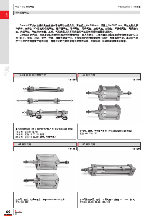
气缸单作用和双作用(符合Camozzi 单作用和双作用 CETOP RP52-P 及 DIN/ISO 6432 标准)16 系列:缸径 8, 10, 12 24 系列:缸径 16, 20, 25 磁传25 系列:缸径 16, 20, 25 磁传,可调气缓冲可以向您提供具有先进水平的气动执行元件,其缸径从 6 ~ 250 mm ,行程从 5 ~ 3500 mm 。
气缸的形式多种多样:有符合 ISO 标准的标准气缸、短行程气缸、导杆气缸、无杆气缸、旋转气缸、制动缸、不锈钢气缸、气液增力缸、夹紧气缸、气缸导向装置、爪钳、气动滑座以及不同类型的气缸安装附件和磁性接近开关。
Camozzi 的气缸,均采用进口的原材料和密封件精制而成。
因其寿命长、工作可靠以及极短的供货周期而被广泛应用于轻工、纺织、印染、食品、包装、橡塑等装备行业。
可根据用户的特殊需要专门设计、制造非标气缸。
本公司气缸在工业生产领域有着广泛的应用,特殊设计的气缸还能用于腐蚀性环境、无菌环境、低温环境和高温环境中。
双作用,磁传,有可调气缓冲(符合 DIN/ISO 6431 标准)缸径 160, 200, 25041 系列气缸双作用,磁传,可调气缓冲(符合 DIN/ISO 6431 标准)缸径 160, 20060 系列气缸,磁传,可调气缓冲(符合 ISO 15552 标准)缸径 32, 40, 50, 63, 80, 100, 1251 / 1.151 / 1.101 / 1.2032 系列串联型和多位型气缸New双作用(可使用符合 DIN/ISO 6431 标准的安装附件)缸径 25, 40, 63, 10045 系列导向装置适用于符合 ISO 6432 标准的气缸 缸径 20, 25适用于符合 ISO 15552 标准的气缸 缸径 32 ~ 10061 系列气缸单作用和双作用,磁传,可调气缓冲(符合 ISO 15552 标准)缸径 32, 40, 50, 63, 80, 100, 12532 系列气缸New单作用和双作用,磁传,防旋转(符合 ISO 21287 标准)缸径 20, 25, 32, 40, 50, 63, 80, 1001 / 1.351 / 1.311 / 1.301 / 1.25气缸16,24 和 25系列微型气缸16 系列:缸径 8, 10, 1224 系列:缸径 16, 20, 25 磁传25 系列:缸径 16, 20, 25 磁传,可调气缓冲16, 24 和 25 系列微型气缸的安装尺寸符合 CETOP RP52-P 欧洲标准和 ISO 6432 标准。
派克液压中文样本

液压注意 – 用户方责任 错误或不当地选择或使用本样本或有关资料阐述的产品,可能会导致人生伤亡及财产损失! 本样本以及其它由派克汉尼汾公司及其子公司、销售公司与授权分销商所提供的资料,仅供用户专业技术人员在对产品和系统的选型进行深入调查考证时参考。
用户应全面分析自身设备的运行工况、适用的工业标准,并仔细查阅现行的样本,以详细地了解产品及系统的相关信息,通过自己的分析和试验,对产品及系统的独立的最终选择负责,确保能满足自身设备的所有性能、耐用性、维修型、安全性以及预警功能等要求。
对于派克或其子公司或授权分销商而言,应负责按用户提供的技术资料和规范,选择和提供适当的元件或系统,而用户则应负责确定这些技术资料和规范对其设备的所有运行工况和能合理预见的使用工况是否充分和准确。
目录目录页次概述 1 订货代号 2 技术参数 4 变量控制器 5 控制选项 “C”, 压力限定(恒压)变量控制器 5 控制选项 “L”, 负载传感及压力限定变量控制器 6 控制选项 “AM”, 带遥控口的标准型先导式压力限定变量控制器 7 控制选项 “AN”, 带ISO 4401 NG06先导阀安装界面的先导式压力限定变量控制器 8 控制选项 “AE”及“AF”, 带电磁比例调节的先导式压力限定变量控制器 9 控制选项 “AMT”, “ALT”及“LOT”, 带最高压力限定的扭矩限定(恒功率)变量控制器 10 P1性能特性 11典型流量特性 11 典型总效率特性 13 典型轴输入功率特性 15 典型噪声特性 18 典型轴承寿命 20 PD性能特性 22典型流量特性 22 典型总效率特性 24 典型轴输入功率特性 26 典型噪声特性 29 典型轴承寿命 31 安装尺寸 33 P1/PD 018 33 P1/PD 028 36 P1/PD 045 40 P1/PD 060 44 P1/PD 075 49 P1/PD 100 54 P1/PD 140 59 变量控制器安装尺寸 65 可提供的扩展的液压产品 75派克汉尼汾备记派克汉尼汾概述简介, 优点派克汉尼汾简介 • 开式回路用轴向柱塞式变量液压泵 • 中压,连续工作压力280 bar • 高驱动转速型,适用于行走机械; 低噪声型,适用于工业应用 • 静音及高效的控制效能 优点 • 总结构尺寸紧凑 • 低噪声• 流量脉动小,进一步降低噪声• 采用弹性密封,不使用密封垫,从而避免外泄漏的产生• 总效率高,功耗小,减小发热• 采用带无泄漏调节装的简单变量控制器 • 符合SAE 及ISO 标准的安装法兰及油口 • 采用圆锥滚柱轴承,使用寿命长 • 全功率后驱动能力• 后部或侧面油口配置可选• 泄油口的配置对水平安装及驱动轴向上垂直安装均适用• 带有最大及最小排量调节选项 • 具有壳体至吸口单向阀选项,可延长轴封寿命 • 使用、维修方便 脉动容腔技术下列图表所示为侧向油口配置P1/PD 18, 28及45泵采用 “脉动容腔” 技术的效果,脉动容腔可降低泵出口处的压力脉动幅值40-60%,这样,无需增加成本来加装噪声缓冲元件,便可大大降低液压系统的整体噪声,P1系列 PD 系列出口压力p / bar平均压力脉动 / b a rP1 045出口压力脉动2600 rpm 无脉动容腔2600 rpm 带脉动容腔订货代号18 ml, 28 ml, 45ml派克汉尼汾P 类型 01 驱动轴 转向R 5密封材料E 油口配置0 壳体-吸口 单向阀 0 排量调节 018 排量 S 安装法兰 及油口 S 轴封 M 应用范围A 设计系列0 通轴驱动选项 C0控制选项0附加控制选项 00油漆 00修改代号系列 P D * 仅适用于045排量, “S”型安装法兰及油口00 标准型, 无修改M2 按要求修改 代号修改代号 * 适用于028及045排量 ** 仅适用于045排量 代号设计系列 A 现行设计系列5 氟碳橡胶 (FPM) 代号密封材料 A 82-2 SAE A M33x2 M27x2 BSPP 1/4”, 3/8” 101-2 SAE B M42x2 M27x2 BSPP 1/4”, 1/2” 101-2SAE B M48x2M33x2Ø38/25DN51/25BSPP 1/4”, 1/2”B ISO M33x2 M27x2 BSPP 1/4”,3/8”ISO M42x2 M27x2 BSPP 1/4”, 1/2” ISO M48x2M33x2Ø38/25DN51/25BSPP 1/4”, 1/2”代号 018排量 028排量 045排量 安装法兰及油口 安装 法兰 螺纹 油口 辅助 油口 安装 法兰 螺纹 油口 辅助 油口 安装法兰螺纹油口法兰 油口辅助 油口 S 82-2 SAE A SAE 16/12 SAE 4/6 101-2 SAE B SAE 20/12 SAE 4/8 101-2SAE B SAE 24/16Ø38/2561系列SAE 4/10M ISO M33x2 M27x2 M12x1.5 M16x1.5 ISO M42x2 M27x2 M12x1.5 M22x1.5 ISO M48x2M33x2Ø38/25DN51/25M12x1.5M22x1.5代号 018驱动轴 028驱动轴 045驱动轴 01 SAE A 11T 花键SAE B-B 15T 花键 SAE B-B 15T 花键02 SAE 19-1平键Ø0.75” SAE B-B 平键Ø1” SAE B-B 平键Ø1” 08— SAE B 13T 花键 SAE B 13T 花键 04 ISO/DIN 平键, Ø20ISO/DIN 平键, Ø25ISO/DIN 平键, Ø25 06 SAE A 9T 花键— — PD 工业液压用 代号 系列P1 行走机械用 代号 排量 018 18 ml/rev (1.10 in 3/rev) 028 28 ml/rev (1.71 in 3/rev) 045 45 ml/rev (2.75 in 3/rev) 代号 类型 P 开式回路用变量柱塞泵 U*通用 代号应用范围 S 工业液压 (PD) M 行走机械 (P1) R 顺时针 (右转)L 逆时针 (左转)代号 转向 代号 轴封 S 单唇轴封 * 并不具有控制功能,仅在运输时予以防护,详情见第7页的控制说明。