温控阀样本(印刷版本)
温控阀演示

故障分析
一般很少出现故障 会出现弹簧断的现象. 会出现弹簧断的现象. 出现气蚀. 出现气蚀. 出现污物堵塞. 出现污物堵塞.
谢谢大家
选型方法和定货要求
确定好进出口温度和流量根据选型流 量曲线表确定口径.. 量曲线表确定口径.. 对于温控阀订货要注意, OB-2000,阀 对于温控阀订货要注意,象OB-2000,阀 体,导阀和温包就要分开来订. 体,导阀和温包就要分开来订.订货要 注明口径和要求以及交货期. 注明口径和要求以及交货期.
毛细管: 毛细管 : 毛细管长度: 毛细管长度 : 连接方式: 连接方式 : 公称直径: 公称直径 :
加热—蒸汽; 被加热—水,油,液体 阀体: 2.0MPa 温包: 1.0MPa º 220 C º -8~183 C 阀体: 球墨铸铁; 主阀,阀体: 不锈钢 先导阀,先导阀座: 不锈钢 隔膜: 不锈钢; 铜管(镀铬) 2m(也生产 3m,5m 的导管) 螺纹式: JIS Rc(PT 螺纹) 2 2 法兰式: JIS 20kgf/cm RF, 10kgf/cm FF 螺纹式: DN15~DN50 法兰式: DN15~DN100
应用场合
本产品作为蒸汽锅炉,各种压力容器, 本产品作为蒸汽锅炉,各种压力容器,仪 表机器等的保护设备及减压阀后的安 全阀使用. 全阀使用. 可用于,蒸汽,空气, 油等工况. 可用于,蒸汽,空气,水/油等工况.
安全阀选型注意事项
给出具体压力范围, 给出具体压力范围,和最大起跳压力 给出所用的工况. 给出所用的工况. 给出流量. 给出流量. 根据具体情况和选型表选择. 根据具体情况和选型表选择. 选型压力要比减压阀的后压高出1.1倍 选型压力要比减压阀的后压高出1.1倍.
我们的温控阀的优点
装有调节柄,无需使用工具,便于调 节。 复阀结构,与单阀相比通过的流量大 影响阀开闭的阀柱压盖密封环使用特 殊衬垫,控温言15A 针对OB-2000而言15A-20A 25A 32A~40A 50A 65A 80A 100A
温控阀
新型采暖系统介绍
一户一表室内水平单管跨越式采暖系统示意图
水平串联单管跨越管系统不易调节,有系统温降,需要确 定好暖气片数量,建议选用上图同程式安装
霍尼韦尔BB阀芯温控阀的阻力损失计算
• 根据以上选型计算得出如下结论:
• 1、在一个40m2的房间,供回水温差△t=20℃时需要的流量是: 77.4kg/h,这时BB阀芯的温控阀的压损为:0.0296kg.即2.96kpa • 2、如果是在温控阀全开状态下,压损只有:0.0156kg.即1.56kpa • 3、温控阀虽然是高阻力阀门,但与系统内其他产品阻力比较,还是 在可控范围内 • 4、霍尼韦尔的BB阀芯的最大流量是:165kg/h,通过以上计算,用在 一个40m2房间的暖气片上,其流量富富有余,在外网有足够压头的情 况下,不会出现流量不够的情况。
•
•
•
•
右图:高阻值温控阀
右图:低阻值温控阀
右图:电热温控阀
暖气恒温阀
TRV
暖气温控阀阀头
• 时尚设计 • 清晰的刻度 • 轻松旋转设定或限位
• 任何角度可读值
• 经济设定点特殊标识
• 标准设计可与其他阀
体配套连接
TRV
温控阀的构造
温控阀头 带长狭缝手轮 保证空气充分 接触感温包 数字化刻度 值标定可选0 设置 整个表面均 为感温包 温度设定限 位销
螺纹联接环
TRV
阀体种类
直型(回水) 直型
水平角型(回水)
垂直角型 水平角型
垂直带弯管
角型
大流量温控阀阀体
TRV
阀芯种类
UBG阀芯
所有阀芯均通用,
BB阀芯
TRV
不同水流量的解决方案
20
HORA气动调节阀样本

阀芯 根据实际工况HORA为用户提供最专业的阀芯。 在大关断压力工况下HORA对阀芯进行平衡阀室 设计,使阀门工作更稳定,寿命更长
密封类型 根据不同介质及温度选择密封材料
3
类型
阀体材质
黄铜 Rg-5 CC491K
铸铁 GG25 EN-JL1040 球铁 GGG-40.3 EN-JS1024 铸钢 GS-C25N 1.0619+N
产品优点 ● 多种阀门型号辅以不同类型的辅件,针对不同工况
可以为用户提供最佳的解决方案 ● 阀门口径DN15-DN800,可为用户提供完整的调节
阀产品系列 ● 同一规格的阀门均提供4种以上的KVs值供用户选
择,提高现场工况的适应性和灵活性 ● 阀门长行程设计,以实现更佳的调节精度 ● 执行机构气开,气关操作方式可灵活选择 ● 执行机构弹簧与膜片有效寿命200百万次,同时没
历经40多年的发展,来自德国北威州Schloß Holte-Stukenbrock的家族企业—HORA公司与世界上著名 的电站设备制造商,能源供应商以及测量-,自动化控制企业建立了良好的伙伴关系。在全世界阀门市 场中HORA品牌以创新,可靠,及卓越的性能得到了广泛的认可。
2008年HORA是德国4家最佳制造商 大 奖M X - A w a r d ( M a n u f a c t u r i n g Excellence Awar)获得者之一
压缩空气
HORA 气动 调节阀
压力调节并联设计
压缩空气
压缩空气
HORA 气动 调节阀
HORA 气动 调节阀
压力调节串联设计
压缩空气
HORA 气动 调节阀
9
压缩空气
阀门样本

一、调节阀系列First、series regulating valve1、型号编制说明The model description:P普通型M密闭型P Normal type M Airtight typeD电动Q气动S手动D Motor-driven Q Pneumatic S Manual风阀高度H Air valve height H风阀宽度W Air valve widthW1 工作温度为-40℃~95℃2工作温度为-55℃~205℃1 the operating temperature -40℃~95℃2 theoperating temperature55℃~205℃D对开式P平行式D Vis-a-vis type P Parallel type创元风量调节阀chuangyuan air volume regulating valve 1.1、型号示例model sample1:CYTD2-1000×500SP 表示创元普通型对开式多叶调节阀,工作温度为-55℃~205℃,宽1000mm,高500mmCYTD2-1000×500SP is Chuangyuan normal vis-a-vis multi-blade regulating valve, the working temperature is -55℃~ 205℃, width is 1000mm, the height is 500mm2、风量调节阀技术参数Air volume regulating valve technical parameters:2.1、风量调节阀框体和叶片采用镀锌钢板制成,无焊点,表面无需涂装;Air volume regulating valve frame and blade made by galvanized steel plates, no weld, the surface doesn’t need paint.2.2、风阀轴承材料为烧结青铜含油轴承,可以耐300℃的高温;The regulating valve bearing material is sintered bronze oiled bearings, can resist high temperature 300℃;2.3、叶片由10×10方形轴连接,轴的材料为45#镀锌钢;Blades are connected by 10×10 square shaft, the material of the bearing is 45# galvanized steel plates 2.4、根据需要可选配可调节风量的执行机构;We can provide implement facility which can regulating the air volume by need.2.5、普通型阀体厚度标准尺寸L=210mm,密闭型阀体厚度标准尺寸L=180mm,也可根据客户需要生产各种特型尺寸;The standard thickness of the normal valve dimension is L=210, the standard thickness of the airtight valve dimension is L=180, customers may also choose a variety of special type size;2.6、风量调节阀的法兰宽度为30mm、40mm,客户可以根据需要选择;The width of the air regulating valve flange is 30mm、40mm,the user can make choice.2.7、密闭阀密封材料为橡胶。
Belimo DN B220VS 20型号温控阀数据表说明书
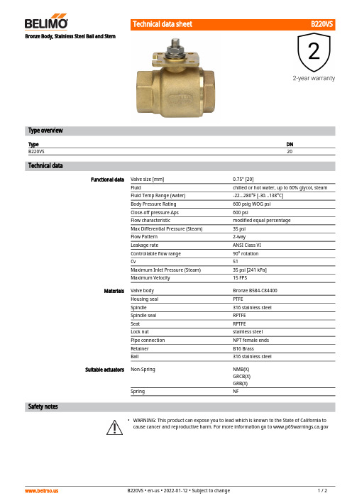
B220VS•Bronze Body, Stainless Steel Ball and StemType overviewType DNB220VS20 Technical dataFunctional data Valve size [mm]0.75" [20]Fluid chilled or hot water, up to 60% glycol, steamFluid Temp Range (water)-22...280°F [-30...138°C]Body Pressure Rating600 psig WOG psiClose-off pressure ∆ps600 psiFlow characteristic modified equal percentageMax Differential Pressure (Steam)35 psiFlow Pattern2-wayLeakage rate ANSI Class VIControllable flow range90° rotationCv51Maximum Inlet Pressure (Steam)35 psi [241 kPa]Maximum Velocity15 FPSMaterials Valve body Bronze B584-C84400Housing seal PTFESpindle316 stainless steelSpindle seal RPTFESeat RPTFELock nut stainless steelPipe connection NPT female endsRetainer B16 BrassBall316 stainless steelSuitable actuators Non-Spring NMB(X)GRCB(X)GRB(X)Spring NFSafety notesWARNING: This product can expose you to lead which is known to the State of California tocause cancer and reproductive harm. For more information go to B220VSApplicationProduct featuresThis valve is typically used in air handling units on heating or cooling coils, and fan coil unit heating or cooling coils. Some other common applications include Unit Ventilators, VAV Box re-heat coils and bypass loops. This valve is suitable for use in a hydronic system with variable flow.This valve is designed with MFT functionally which facilitates the use of various control input.Up to 35 psi steam1/2" - 2" 600 PSIG WOG, Cold Non-Shock Federal Specification: WW-V-35C, Type II Composition: BZ Style: 3Flow/Mounting detailsDimensionsType DN B220VS20B220VS+GRC..N4AB CD E F 14.1" [358]3.2" [82]12.0" [305]11.1" [282]3.4" [86]3.4" [86]FootnotesOn/Off or Floating Point, Non-Spring Return,24 VTechnical dataElectrical data Nominal voltage AC/DC 24 VNominal voltage frequency50/60 HzPower consumption in operation8 WPower consumption in rest position 2.5 WTransformer sizing11 VA (class 2 power source)Electrical Connection Terminal blocksOverload Protection electronic thoughout 0...90° rotationFunctional data Direction of motion motor selectable with switch 0/1Manual override under coverAngle of rotation90°Angle of rotation note adjustable with mechanical stopRunning Time (Motor)35 s / 90°Running time motor note constant, independent of loadNoise level, motor45 dB(A)Position indication Mechanically, 5...20 mm strokeSafety data Degree of protection IEC/EN IP66/67Degree of protection NEMA/UL NEMA 4XEnclosure UL Enclosure Type 4XAgency Listing cULus acc. to UL60730-1A/-2-14, CAN/CSAE60730-1:02, CE acc. to 2014/30/EU and2014/35/EUQuality Standard ISO 9001Ambient temperature-22...122°F [-30...50°C]Ambient temperature note-40...50°C for actuator with integrated heatingStorage temperature-40...176°F [-40...80°C]Ambient humidity Max. 100% RHServicing maintenance-freeMaterials Housing material Die cast aluminium and plastic casing†Rated Impulse Voltage 800V, Type of action 1.AA, Control Pollution Degree 3AccessoriesElectrical accessories Description TypeBattery backup system, for non-spring return models NSV24 USBattery, 12 V, 1.2 Ah (two required)NSV-BATAuxiliary switch 1 x SPDT add-on S1AAuxiliary switch 2 x SPDT add-on S2AFeedback potentiometer 140 Ω add-on, grey P140A GRFeedback potentiometer 1 kΩ add-on, grey P1000A GRFeedback potentiometer 10 kΩ add-on, grey P10000A GRFeedback potentiometer 2.8 kΩ add-on, grey P2800A GRFeedback potentiometer 500 Ω add-on, grey P500A GRFeedback potentiometer 5 kΩ add-on, grey P5000A GR Factory add-on option only Description TypeHeater, with adjustable thermostat N4 Heater Add-on24V (-H) Electrical installationINSTALLATION NOTESProvide overload protection and disconnect as required.Actuators may also be powered by DC 24 V.For triac sink the Common connection from the actuator must be connected to the Hotconnection of the controller. Position feedback cannot be used with a triac sink controller; theactuator internal common reference is not compatible.IN4004 or IN4007 diode. (IN4007 supplied, Belimo part number 40155).Actuators are provided with a numbered screw terminal strip instead of a cable.Meets cULus requirements without the need of an electrical ground connection.Warning! Live electrical components!During installation, testing, servicing and troubleshooting of this product, it may be necessaryto work with live electrical components. Have a qualified licensed electrician or other individualwho has been properly trained in handling live electrical components perform these tasks.Failure to follow all electrical safety precautions when exposed to live electrical componentscould result in death or serious injury.Wiring diagramsOn/OffFloating Point。
ASME ANSI B16.5 温控阀说明书

800-543-9038 866-805-7089 203-791-8396Technical Data Servicechilled, hot water, 60% glycol, steam to 50 psi Flow characteristic modifi ed equal percentage, unidirectional Controllable fl ow range 82°Sizes2” to 24"Type of end fi tting for use with ASME/class 125/150 fl angeMaterials Body Disc Seat ShaftGland seal Bushingscarbon steel full lug 316 stainless steel RPTFE17-4 PH stainless PTFEglass backed PTFEMedia temperature range -20°F to 400°F [-30°C to 204°C]Body pressure rating ANSI Class 150Close-off pressure 285 psiRangeability100:1 (for 30 deg to 70 deg range)Maximum velocity 32 FPS Leakagebubble tight•Bubble tight shut-off to ANSI Class 150 Standards •Long stem design allows for 2” insulation minimum• Valve Face-to-face dimensions comply with API 609 & MSS-SP-68•Designed to be installed between ASME/ANSI B16.5 Flanges •Completely assembled and tested, ready for installationApplicationThese valves are designed to meet the needs of HVAC and Commercial applications requiring positive shut-off for liquids at higher pressures and temperatures. Typical applications include chiller isolation, cooling tower isolation, change-over systems, large air handler coil control, bypass and process control applications. The large C v values provide for an economical control valve solution for larger fl ow applications.Dead End ServiceUtilizes larger retainer ring set screws to allow the valve to be placed at the end of the line without a down stream fl ange in either fl ow direction while still holding full pressure.MOD ON/OFF ValveSize C v 10°20°30°40°50°60°70°80°90°F650-150SHP 2”102 1.50 6.10142639567799102F665-150SHP 2½”146 2.208.8020375580110142146F680-150SHP 3”228 3.4014325787125171221228F6100-150SHP 4”451 6.802763114171248338437451F6125-150SHP 5”7141143100180271393536693714F6150-150SHP 6”1103176615427841960782710701103F6200-150SHP 8”2064311242895207841135154820022064F6250-150SHP 10”35175321149288613361934263834113517F6300-150SHP 12”483773290677121918382660362846924837F6350-150SHP 14”685790392914164624813592489865306857F6400-150SHP 16”92871325311230222933614865663488459287F6450-150SHP 18”11400171684159638734332627085501127011400F6500-150SHP 20”144202078281932347852447590103501380014420F6600-150SHP 24”22050315126029405292789011550157502100022050F6 Series 2-Way, ANSI Class 150 Butterfl y Valve Reinforced Tefl on Seat, 316 Stainless Disc2-way ValvesSuitable ActuatorsValve Nominal SizeType Non Fail-SafeFail-SafeSpring Return Electronic C v90°C v 60°Inches ANSI 150 2-way 150150150102562F650-150SHPG M S e r i e sP R S e r i e sA F S e r i e sG K S e r i e s146802½F665-150SHP2281253F680-150SHP 4512484F6100-150SHP 7143925F6125-150SHP P K R 11036076F6150-150SHP 206411358F6200-150SHP S Y S e r i e s (2 Y e a r W a r r a n t y )3517193410F6250-150SHP 4837266012F6300-150SHP 6857359214*F6350-150SHP 9287486516*F6400-150SHP 11400627018*F6450-150SHP 14420759020*F6500-150SHP 220501155024*F6600-150SHP866-805-7089 203-791-8396 LATIN AMERICA / CARIBBEANMaximum Dimensions (Inches)F650-150SHP 2”102 1.759.009.0019.50 4.7545/8-11 UNC 2*AF150Spring Return F665-150SHP 2½”146 1.889.009.0020.00 5.5045/8-11 UNC 150F680-150SHP 3”2281.929.009.0020.50 6.0045/8-11 UNC 150F6100-150SHP4”451 2.139.009.0021.007.5085/8-11 UNC 150F650-150SHP 2”102 1.759.009.0019.50 4.7545/8-11 UNC GK 285Electronic Fail-Safe F665-150SHP 2½”146 1.889.009.0020.00 5.5045/8-11 UNC 285F680-150SHP 3”228 1.929.009.0020.50 6.0045/8-11 UNC 285F6100-150SHP 4”451 2.139.009.0021.007.5085/8-11 UNC 150F6100-150SHP 4”4512.139.009.0021.007.5085/8-11 UNC 2*GK 285F650-150SHP2”102 1.759.009.0019.50 4.7545/8-11 UNC GM 285Non-Spring Return Electronic Fail-Safe (K)F665-150SHP 2½”146 1.889.009.0020.00 5.5045/8-11 UNC 285F680-150SHP 3”228 1.929.009.0020.50 6.0045/8-11 UNC 285F6100-150SHP 4”451 2.139.009.0021.007.5085/8-11 UNC 150F6100-150SHP 4”451 2.139.009.0021.007.5085/8-11 UNC 2*GM285F650-150SHP 2”1021.7510.0015.0014.00 4.7545/8-11 UNC PR/PK285F665-150SHP2½”146 1.8810.0016.0014.00 5.5045/8-11 UNC 285F680-150SHP 3”2281.9210.0017.0015.00 6.0045/8-11 UNC 285F6100-150SHP4”451 2.1310.0018.0016.007.5085/8-11 UNC 285F6125-150SHP 5”7142.2510.0019.0016.008.5083/4-10 UNC 285F6150-150SHP6”1103 2.2910.0020.0017.009.5083/4-10 UNC 285F6200-150SHP 8”20642.5012.0012.0032.0011.7583/4-10 UNC SY4…285F6250-150SHP 10”3517 2.8112.0012.0033.0014.25127/8-9 UNC SY4…285F6300-150SHP 12”4837 3.2312.0012.0035.0017.00127/8-9 UNC SY4…150SY5…285F6350-150SHP 14”6857 3.6214.0014.0036.0018.75121-8 UNC SY5…150SY7…285150F6400-150SHP 16”9287 4.0014.0014.0037.5021.25161-8 UNC SY8…285F6450-150SHP 18”11400 4.5014.0014.0042.2522.7516 1 1/8-8 UNC SY7…150SY8…285F6500-150SHP 20”14420 5.0014.0014.0049.5025.0020 1 1/8-8 UNC SY8…150SY10…285F6600-150SHP24”220506.0614.0014.0056.2529.50201 1/4-8 UNCSY10…150F6 Series 2-Way, ANSI Class 150 Butterfl y ValveReinforced Tefl on Seat, 316 Stainless DiscDimension “A” does not include flange gaskets. (2 required per valve)Application Notes1. Valves are rated at 285 psi differential pressure in the closed position @ 100°F media temperature.2. V alves are furnished with lugs tapped for use between ANSI Class 125/150fl anges conforming to ANSI B16.5 Standards.3. 2-way assemblies are furnished assembled, calibrated and tested, ready for installation.4. D imension “D” allows for actuator(s) removal without the need to remove the valve from the pipe.5. W eather shields are available, dimensional data furnished upon request.6. F lange gaskets (2 required, not provided with valve) MUST be used between valve and ANSI fl ange.7. F lange bolts are not included with the valve. These are furnished by others.DB CABHCSHP seriesvalves have a preferred flow direction.P r e f e r r e d F l o w r a t ePRBUP-3-TApplicationOn/Off, Floating Point, Non Fail-Safe, 24...240 V, NEMA 4XTechnical dataElectrical dataNominal voltageAC 24...240 V / DC 24...125 V Nominal voltage frequency 50/60 Hz Power consumption in operation 20 W Power consumption in rest position 6 WTransformer sizing 20 VA @ AC/DC 24 V (class 2 power source), 23 VA @ AC/DC 120 V, 52 VA @ AC 230 V Auxiliary switch2 x SPDT,3 A resistive (0.5 A inductive) @ AC 250 V, 1 x 10° / 1 x 0...90° (default setting 85°)Switching capacity auxiliary switch 3 A resistive (0.5 A inductive) @ AC 250 V Electrical Connection Terminal blocks, (PE) Ground-Screw Overload Protectionelectronic thoughout 0...90° rotation Functional dataDirection of motion motor reversible with app Manual override 7 mm hex crank, supplied Angle of rotation 90°Running Time (Motor)35 s Noise level, motor 68 dB(A)Position indicationintegral pointer Safety dataDegree of protection IEC/EN IP66/67Degree of protection NEMA/UL NEMA 4XEnclosure UL Enclosure Type 4XAgency ListingcULus acc. to UL60730-1A/-2-14, CAN/CSA E60730-1:02, CE acc. to 2014/30/EU and 2014/35/EU Quality Standard ISO 9001Ambient temperature -22...122°F [-30...50°C]Ambient humidity Max. 100% RH Servicingmaintenance-free Weight Weight13 lb [5.9 kg]MaterialsHousing materialdie cast aluminium polycarbonate coverProduct featuresPR Series valve actuators are designed with an integrated linkage and visual position indicators. For outdoor applications, the installed valve must be mounted with the actuator at or above horizontal. For indoor applications the actuator can be in any location including directly under the valve.PRBUP-3-T Operation The PR series actuator provides 90° of rotation and a visual indicator shows the position of thevalve. The PR Series actuator uses a low power consumption brushless DC motor and iselectronically protected against overload. A universal power supply is furnished to connectsupply voltage in the range of AC 24...240 V and DC 24...125 V. Included is a smart heater withthermostat to eliminate condensation. Two auxiliary switches are provided; one set at 10° openand the other is field adjustable. Running time is field adjustable from 30...120 seconds by usingthe Near Field Communication (NFC) app and a smart phone.†Use 60°C/75°C copper wire size range 12...28 AWG, stranded or solid. Use flexible metalconduit. Push the listed conduit fitting device over the actuator’s cable to butt against theenclosure. Screw in conduit connector. Jacket the actuators input wiring with listed flexibleconduit. Properly terminate the conduit in a suitable junction box. Rated impulse Voltage 4000V. Type of action 1. Control pollution degree 3.AccessoriesMechanical accessories Description TypeHand crank for PR, PKR, PM ZG-HND PR Electrical installationMeets cULus requirements without the need of an electrical ground connection.Universal Power Supply (UP) models can be supplied with 24 VAC up to 240 VAC, or 24 VDC upto 125 VDC.Disconnect power.Provide overload protection and disconnect as required.Two built-in auxiliary switches (2x SPDT), for end position indication, interlock control, fanstartup, etc.Actuators may be controlled in parallel. Current draw and input impedance must be observed.Warning! Live electrical components!During installation, testing, servicing and troubleshooting of this product, it may be necessaryto work with live electrical components. Have a qualified licensed electrician or other individualwho has been properly trained in handling live electrical components perform these tasks.Failure to follow all electrical safety precautions when exposed to live electrical componentscould result in death or serious injury.Wiring diagramsOn/OffPRBUP-3-T On/OffFloating Point Auxiliary SwitchesDimensionsDimensional drawings。
派克阀门样本Parker Valve

O
Female BSPP thread (ISO 1179-1) / Female BSPP thread (ISO 1179-1) / Female BSPP thread (ISO 1179-1)
O5
Catalogue 4100-8/UK
O4
Catalogue 4100-8/UK
Visual index 2/2-way ball valves
KH (S) p. O36源自ValvesKH (71) p. O37
EO 24° cone end / EO 24° cone end KH-BSPP (S) p. O38
Female BSPP thread (ISO 1179-1) / Female BSPP thread (ISO 1179-1)
Non return valve cartridge I-TL / p. O20
Internal parts of non return valve O2
Catalogue 4100-8/UK
Visual index Non return valves with O-Lok® connections
RHV82EDMLOS / p. O27
Male metric thread – ED-seal (ISO 9974) / O-Lok® ORFS end
RHZ42EDMLOS / p. O24
O-Lok® ORFS end / Male BSPP thread – ED-seal (ISO 1179)
KH-NPT (71) p. O41
Female NPT thread (SAE 476) / Female NPT thread (SAE 476)
nordic阀门遥控样本

Nordic Flow Control Pte LtdSubsidiary of Nordic Group Limited, listed on the SGX 5 Kwong Min Road, Singapore 628708Tel: (65) 6848 4400 Fax: (65) 6848 4411 Customer Care Hotline: (65) 6425 2337Customer Care: customercare@Sales Enquiries: sales@Marketing & Communications: marketing@ Incorporated in 1998, Nordic Flow Control started out as a service agent.Through vision and determination, we have forged ahead to become aglobal manufacturer and system integration solutions provider for Marine,Oil and Gas control systems, with a sales and support network that spansAsia and Europe.To stay ahead of the competition, we are constantly raising the bar in qualityand technological creativity. Nordic Flow Control’s Integrated Control andManagement Systems, will meet any vessel automation needs. Fromproduction to installation, our professional and experienced engineers willbe there every step of the process to ensure customers get the mostreliable, user-friendly and technologically advanced control systems thatperform above their expectationsBacked by international accreditations from various marine classificationbodies, including ISO 9001:2000 by ABS, Nordic Flow Control’s one-stopintegrated solution has been installed in hundreds of vessels and drillingrigs across the globe. Made from the toughest materials and able to withstandthe most demanding of marine and offshore situations, our growing referencelist bears testament to the reliability of our systems.TECHNICAL SPECIFICATIONS – ACTUATOR DRAWINGSOur HPU is delivered as a one skid-mounted unit, and it contains thefollowing main components:s /IL RESERVOIR WITH A CAPACITY TO BE CALCULATED DEPENDING ON THEnumber of actuatorss %LECTRIC MOTORS TO BE CONTROLLED FROM SEPARATE STARTERSs (YDRAULIC PUMPs 6ALVES AND -ANIFOLDSs !CCUMULATOR AND CHARGING KITs 3TARTER #ONTROL 0ANEL AND #ONTROL 0ANELs 3IGHT 'LASSs ,EVEL 3WITCHESs 0RESSURE 3WITCHES FOR 34!24 34/0 OF PUMPS AT PRESET VALUESs 3AFETY 6ALVESs 0RESSURE 'AUGEs /IL TEMPERATURE MONITORINGThe HPU has been reviewed as an extremely reliable power unit. Fromstandard to customised units, they are very well designed. Our standardunits come with two motors, for back up purposes and to extend thelifespan of our HPU.!LL MOTORS THE ELECTRICAL CABINETS AND ALL OTHER EQUIPMENT COME WITHIP55 protection to ensure greater performance.TECHNICAL SPECIFICATIONSReservoir Volume 150l 250l 350l 0UMP #APACITY 0UMPS L MIN L MIN L MIN Max Working Pressure 170 bar%LECTRIC -OTOR NOS6OLTAGE 6 (Z 0H POLE0OWER #ONSUMPTION KW EACH KW EACH KW EACH "LADDER !CCUMULATOR L LX L Our HPU is designed to be user-friendly. The layout for the electricaland hydraulic components is placed systematically and the open designallows for easy access during maintenance.Featuress %XCELLENT DEPENDABILITYs ,OCAL AND REMOTE CONTROLs ,OW LEVEL HIGH PRESSURE HIGH TEMPERATURE ALARMSs !UTOMATIC AND MANUAL CONTROL FOR MOTOR 34!24 34/0s "ACKUP RESERVOIR ALLOWING FOR AUTO TRANSFER BETWEEN THE TWOreservoirs if neededs )0 PROTECTION ON MOTORS ELECTRICAL CABINET AND EQUIPMENTs#OMES IN THREE STANDARD SIZES OF AND LITRES RESERVOIRSHYDRAULIC SYSTEM ACCESSORIESDouble Pilot Block4HE $OUBLE 0ILOT $0 "LOCK IS DESIGNED TO BE USED ON BOTH OUR .2! AND .(2 SERIES OF DOUBLE ACTING ACTUATORS )T CONTAINS A THROTTLING VALVE WHICH IS USED FOR ADJUSTING SPEED WHEN REGULATING THE VALVE S OPENING AND CLOSING speeds.Featuress ! $OUBLE 0ILOT $0 #HECK 6ALVE WITH HYDRO LOCK FUNCTION TO PROVIDE FOR LOSS OF PRESSURE IN OIL CHAMBER CAUSED BY external factorss 4HROTTLING 6ALVE FOR SPEED ADJUSTMENT TO MINIMISE WATER HAMMERING EFFECTs ! PRESSURE RELIEF VALVE SET AT BARS TO PREVENT OVER PRESSURISING THE ACTUATORS BY RELEASING THE HYDRAULIC OIL FROM THE CHAMBER IF THE PRESSURE INSIDE GOES HIGHER THAN TO BARs ! HAND PUMP CONNECTION THAT ALLOWS EMERGENCY OPERATION BY MEANS OF A PORTABLE (AND 0UMP s 1UICK COUPLING TO CONNECT THE HAND PUMP FOR EMERGENCY OPERATION OF ACTUATOR DURING POWER FAILURE Operation&OR USE WITH .ORDIC $OUBLE !CTING !CTUATORSs $0 "LOCK CONSISTS OF A (YDRAULIC $0 #HECK 6ALVE QUICK CONNECTION FOR EMERGENCY HAND PUMP OPERATION PRESSURE RELIEF VALVES ATTACHMENT AND SPEED ADJUSTMENTs !BLE TO BE USED ON ALL .ORDIC ACTUATOR MODELSFor use with Submerged Actuators:s $0 IS -OUNTED ON THE $0#/ $ECK 0LATE "LOCK AT THE DECK FOR EASY MANUAL OVERRIDE OPERATIONS s ! 3UBMERGED #AP WILL BE ADDED ONTO THE ACTUATOR S INDICATORs 30#/ 3UBMERGED 0LATE "LOCK WILL BE PLACED ON THE ACTUATORTHROTTLE VALVESAC Block .ORDIC &LOW #ONTROL S 3!# "LOCK IS DESIGNED TO BE USED ON OUR .2! AND .(2 SERIES SINGLE ACTING ACTUATORS 4HE 3!# consists of a quick connection for emergency hand pump operation as well as a connection for throttle valves.! THROTTLING VALVE IS ALSO INCORPORATED FOR ADJUSTING SPEED WHEN REGULATING THE VALVE S OPENING CLOSING SPEED 4HISfeature also greatly reduces the water-hammering effect.Features s 4HROTTLING VALVES TO ADJUST THE SPEED OF THE HYDRAULIC OIL mOW s 1UICK COUPLING TO CONNECT THE HAND PUMP DURING EMERGENCY CONDITIONS OR HYDRAULIC POWER FAILURE TO OPEN OR close the valve Operation &OR USE WITH .ORDIC 3INGLE !CTING !CTUATORS s 4HE 3!# "LOCK CONSISTS OF A QUICK CONNECTION FOR EMERGENCY HAND PUMP OPERATION AND SPEED ADJUSTMENT s 3PRING ACTION BY MEANS OF DISC SPRINGS For use with Submerged Actuators:s 3!# "LOCK IS MOUNTED ON THE $0#/ $ECK 0LATE "LOCK AT THE DECK FOR EASY MANUAL OVERRIDE OPERATIONS s ! 3UBMERGED #AP WILL BE ADDED ONTO THE ACTUATOR S INDICATOR s 30#/ 3UBMERGED 0LATE "LOCK WILL BE PLACED ON THE ACTUATOR Deck Plate (DPCO)$0#/ IS THE DECK PLATE USED TO MOUNT THE $0 3!#block in the dry area for the actuator in submerged conditions.Submerged Applications AccessoriesSubmerge Plate (SPCO)"Y USING THE 30#/ 7E CAN COVER 0ORTS ! AND " WITH THEACTUATOR IN SUBMERGED CONDITIONS 4HERE WILL BE A $0 3!# "LOCK IN THE DRY AREASubmerged Cap The pinion gear is covered by the submerged cap whenthe actuator is in submerged conditions to prevent wateringress.DP BlockManifoldOur manifolds work with a stacked design that comes in 6-station blocks. The design allows placements behind each manifold in a solenoid valve cabinet and very compact hydraulic systems can be built upon each station."ESIDES THE ! AND " USER PORTS THERE ARE TWO THROTTLE STOP VALVES ON EACH station that regulates the flow and can be closed for repairs at the actuators.The manifolds are provided with screws and recesses for cabinet mounting.Featuress #OMPACT AND UNIQUE DESIGNs 4HROTTLE VALVES ON EACH STATIONs 3YSTEMS BLEED VALVE ON EACH MANIFOLDs(AND PUMPS CONNECTIONS FOR EMERGENCY OPERATIONTECHNICAL SPECIFICATIONSWorking Pressure 135 barMaximum Test Pressure 200 bar&ITTING #ONNECTION v "300Weight of Nordic 6-Station 6 kgWeight of Bottom Section 2 kgWeight of Top Section 1 kgMaterials-ANIFOLD "OTTOM AND 4OP "LOCK !LUMINIUM 4 4HROTTLE 3TOP 6ALVE "RASSHand Pump Connection SteelSeal RingNBRTop Block In the top block, a system bleed valve an d a pressure gauge TO BAR FOR 0 LINE PRESSURE ARE INCORPORATED When purging the pressure line P to the tank line T, the bleed valve is to be opened.Bottom Block In the bottom block, there are two han d pump connections on the P and T ports, which are incorporated for the emergency operation of the entire manifold.Before using the hand pump connection, the two stop valves that are incorporated in the P and T ports should be closed.Blank Plate The blank plate is used for blanking off connections that are not used on the manifold.! CHECK VALVE IS USED IN THE MANIFOLD 4 LINE IN ORDER to have flow moving in one direction, preventing back pressure.The check valve is a stan dard feature in our man ifold system.Check Valve 4HE THROTTLE VALVE IS USED FOR SPEED ADJUSTMENTS AND shut off.ValveComponentsFEEDBACK UNITSMODULATING LIMIT SWITCH.ORDIC &LOW #ONTROL S -ODULATING ,IMIT 3WITCH FOR MONITORING AND MODULATING VALVES IS SUITABLE FOR USE IN HAZARDOUS AREAS )TS ROBUST AND COMPACT DESIGN CONFORMS TO %. AND %. WHICH MAKES IT ALSO SUITABLE FOR :ONE AND :ONE APPLICATIONSFeaturess !LUMINIUM CASTING WITH POWDER COATING BODYs "OLTS ON VISUAL POSITION INDICATOR MAKING IT SECURE AND WEATHERPROOFs 1UICK SET CAMs $UAL CABLE ENTRYs #APTIVE COVER BOLTSs%ASY MOUNTING BRACKETON/OFF LIMIT SWITCH 4HE /. /&& ,IMIT 3WITCH IS A ROTARY POSITION INDICATOR USED TO MONITOR THE /0%. #,/3% POSITION OF THE VALVE The dome position indicator is constructed from high impact resistant polycarbonate material which offers instant recognition of valve position from up to 50 metres.Features s 6ISUAL 0OSITION )NDICATOR s 1UICK SET CAM s -ULTI POINT TERMINAL STRIP s $UAL WIRE POTTING s #APTIVE COVER BOLTS s %ASY MOUNTING BRACKET TECHNICAL SPECIFICATIONS %NCLOSURE 7EATHERPROOF )0 4EMPERATURE 2ANGE ª# TO ª# 4ERMINAL 3TRIP POINTS Position Indicator 0 to 90°C : Open – Yellow, Closed - Red 3HAFT STAINLESS STEEL -ICRO 3WITCHES 5SED IN 5, #3! APPROVED )NSERTS "RONZE / 2INGS .ITRILE 2UBBER Cams Polycarbo n ate 3PRING #OVER 3CREWS STAINLESS STEEL 6OLTAGE -AXIMUM 6 !# OR $##URRENT ! 6 OR $# ! b (0 !# ! 6 4 #ABLE %NTRY X b v 0& 04 .04 3WITCH 4YPE 30$4 -ECHANICAL SWITCHES 0ROXIMITY SENSORS Painting Polyester powder coating with black colour "RACKET 0LASTIC 0LATE STEEL TECHNICAL SPECIFICATIONS%NCLOSURE &LAMEPROOF %%XD ))" 4 AND %%XD ))#T6 Weatherproof0ROTECTION )0 )0#OATING %XTERNAL POWDER COATED!NODIZED SURFACE AGAINST CORROSION /PTIONAL !REA :ONE 'AS #LASSIlCATION %XD ))" # 4 4EMPERATURE 2ANGE ª# TO ª#(IGHER TEMPERATURE AVAILABLEUPON REQUEST#ABLE %NTRY X 04 b vX 0& b vX .04 b v2 x M20 X 1.5 upon request-AXIMUM4ERMINAL TERMINAL STRIPSFOR SWITCHES FOR SOLENOIDCONNECTIONPosition Monitoring Indicator 0°C to 90°CYellow - Open, Red - CloseSwitches 2 x mechanical switchesPotentiometer Position transmitter 0 to 1 K-OUNTING "RACKET 6$) 6$% .!-52TECHNICAL SPECIFICATIONSMaximum Working Pressure 135 barMaximum Test Pressure 200 barRotation Indication Pointer4EMPERATURE 2ANGE ª# TO ª#(YDRAULIC -EDIA !CID FREE HYDRAULIC OILViscosity 15 to 200 cSt-AXIMUM mOW RATE BAR L MINWeight 1.3kg&ILTRATION REQUIREMENTS «M ABSOLUTE OR lNER#ONNECTION &ACE #%4/0 2 ( SIZEMaterials (OUSING !LUMINIUMScrews Stai n less steel VALVE POSITION INDICATORWhen the actuator is submerged, the measurement of the actuator position by mean s of direct in dication is n ot feasible. Nordic Flow Con trol’s Valve 0OSITION )NDICATOR 60) CAN BE USED FOR BOTH NON SUBMERGED AND SUBMERGED applications, allowing accurate actuator measurement regardless of setup.The basic intention of the VPI is to receive and measure position feedback from the actuator. The working principle behind is through the measurement of the OIL DISPLACEMENT mOW ! GEAR WHEEL CONNECTED TO THE OIL mOW ROTATES WHEN the actuator is rotated. The rotation of the gear wheel is also connected to a 3-wire potentiometer. The output signal from the potentiometer ranges from 0 to 1 K ¾.Featuress %XCELLENT DEPENDABILITYs 7ELL CRAFTED TO SUIT MOST QUARTER TURN VALVESs %NGINEERED ESPECIALLY FOR -ARINE AND /FFSHORE APPLICATIONSs 2ECEIVE POSITION FEEDBACK FROM ACTUATORSs 2OTATIONAL GEAR WHEEL IS CONNECTED TO A WIRE POTENTIOMETERs /UTPUT SIGNAL FROM THE POTENTIOMETER RANGES FROM TO +¾VALVE POSITION INDICATORSIDE VIEWTOP VIEW VPI WITH SOLENOID LOCAL INDICATOR .ORDIC &LOW #ONTROL ,OCAL )NDICATOR IS USED TO DISPLAY THE POSITION OF THE VALVE /0%. #,/3% LOCALLY IF THE VALVE IS IN a submerged location. Once the incoming pressure exceeds the pressure setting on the pressure relief valve inside the local indicator, the oil would flow to a small chamber, causing the piston to move towards one side; as a result THE INDICATOR WOULD DEmECT AND GIVES THE /0%. #,/3% STATUS OF THE VALVE TECHNICAL SPECIFICATIONS (OUSING !LUMINIUM C W TYPE ANODIZING Screws Stai n less steel Working Pressure 135 bar Weight 0.7 kg (YDRAULIC -EDIA !CID FREE HYDRAULIC OIL Viscosity 15 to 200 cSt &ILTRATION 2EQUIREMENTS «M ABSOLUTE OR lNER 4EMPERATURE 2ANGE # TO #Local Indicator – Double Acting (Without Remote Signal)TECHNICAL SPECIFICATIONS (OUSING !LUMINIUM C W TYPE ANODIZING Screws Stai n less steel Working Pressure 135 bar Weight 0.7 kg (YDRAULIC -EDIA !CID FREE HYDRAULIC /IL Viscosity 15 to 200 cSt &ILTRATION 2EQUIREMENTS «M ABSOLUTE OR lNER4EMPERATURE 2ANGE # TO C Local Indicator – Single Acting (Without Remote Signal)。
- 1、下载文档前请自行甄别文档内容的完整性,平台不提供额外的编辑、内容补充、找答案等附加服务。
- 2、"仅部分预览"的文档,不可在线预览部分如存在完整性等问题,可反馈申请退款(可完整预览的文档不适用该条件!)。
- 3、如文档侵犯您的权益,请联系客服反馈,我们会尽快为您处理(人工客服工作时间:9:00-18:30)。
80 267 171 – 200 245 22 160 18
4BO/BR
100 403 217 – 224 308 24 180 18
5BO/BR
125 489 241 – 254 349 26 210 18
–
–
–
–
–
–
–
–
4 120.6 19 4
4 120.6 19 4
4 139.7 19 4
8 152.6 19 4
41 (105)
35-45 (95-113)
55 (131)
43 (110)
38-47 (100-117)
56 (133)
46 (115)
40-50 (104-122)
61 (142)
–
49 (120)
43-54 (110-130)
66 (150)
54 (130)
51-60 (124-140)
型号
11/2BO 2BO/BH/BG 2BF 2BC/BR 21/2BO/BR 3BO/BR 33BO/BR 4BO/BR 5BO/BR
6BO/BR
8BO/BR
重量(千克)
青铜
铸铁/球墨铸铁
钢/不锈钢
铝
13
11
N/A
N/A
13
11
N/A
N/A
22
18
N/A
7
26
18
20
N/A
29
24
34
10
36
27
安装位置:
任意方位
连接口:
低于名义温度 - A与B口连接 高于名义温度 - A与C口连接
阀体材质: 密封材质:
铝合金,青铜,铸铁,球墨铸铁,钢及不锈钢(参见型号代码表) 氟橡胶,氰橡胶,氯丁橡胶和乙烯丙烯橡胶
阀的尺寸(名义尺寸):
40,50,65,80,100,125,150和200mm(1-1/2",2",2-1/2",3",4",5",6"和8")
10-18 (50-65)
30 (86)
24 (75)
20-30 (68-86)
38 (100)
32 (90)
27-35 (81-95)
43 (110)
35 (95)
29-41 (85-105)
49 (120)
38 (100)
34-42 (93-108)
50 (122)
–
注:温控阀阀芯动作示例
温度设定
AMOT温控阀提供了宽广的温度设定范围。淡水系统控制温度一般在71摄氏度到88摄氏度,海水系统一般不超过49摄氏度。 对于润滑油系统及冷却/加热系统所要求的特殊温度,我们也可以根据设备制造商的需求,量身定做。 这里所提及的温度是冷却水系统"分流"模式下名义工作温度。 对于"混流"模式及润滑油系统,由于流量,粘性及其它系统特性的不同,该温度会比名义温度高约1到2度。
10Bar (150 Psi)
22Bar (325 Psi) 16Bar (230Psi) 45Bar (655Psi) 6Bar (90Psi)
4
尺寸(mm)
ND10/16
125/150LB
型号
NB F
H
J
DW
t
K
d
n
K
d
n
11/2BO
40 246 91 97 – 140 –
–
–
2BO/BH/BG 50 246 91 97 – 139 –
功能:
在自动调节模式下,温控阀自动调节控制温度。 当顺时针旋转阀顶部的调节螺母,可以强制将阀芯调节到 "热态"位置,从而不受实际温度的影响。 每个手动调节器均带有一位置显示器,可以很直观的显示 阀芯所处相对位置。每个阀芯的手动调节器均是一一对应。 手动调节器通常只在紧急状态,或阀芯失效的时候使用。
铸铁,球墨铸铁和青铜 型号BO,BG,BF,BC&BR(33B除外) 2BH(铸铁) 钢 150LB,ND10&ND16 钢 300LB 33B
AMOT控制阀
逾50年的品质及保证
温度控制阀
自力式内部感温设计
应用
s 热交换/热回收 s 润滑油系统 s 高温缸套水热交换系统 s 低温二次供水系统 s 节水应用系统 s 锅炉进水温度控制系统
s 热电联产、冷却塔系统 s 制冷系统 s 混流、分流应用系统 s 温度调节系统 s 工艺过程温度控制 s 保温系统
典型安装应用流程图
分流应用系统
混流应用系统
热交换
C AMOT B A
机组 旁通 (热负荷)
C AMOT
A
B 恒温阀
热交换
机组
(热负荷) AMOT恒温阀
热
B AMOT C
冷
A
BC A
热交换
控制进口温度
泵
锅炉回水应用系统
水泵备选安装位置
去系统
锅炉
AMOT恒温阀
BC A
系统回
泵
控制出口温度
节水应用系统
如图所示,AMOT恒温阀始终 控制系统以最小水流量流经 热交换器,从而达到节水目 的。该恒温阀需配有内部泄 漏孔,用于感测温度
尤其适用于无法添加(或没有添加)防冻剂的应用场合。 • 适用于温控阀用作两通阀(B口封堵)的场合。
当回路温度低且阀关闭时,通过泄漏孔保持一定流量流经阀芯,保持感温包持续感温,从而确保温控阀工作正常。
3
B
B阀通用特性
流量:
10 - 450 M3/Hr
应用: 分流和混流
(用于高强度/高压场所) s 球墨铸铁BS: 2789 Grade420/12
(高性能铸铁) s 不锈钢BS: 3100 Grade 316C16F
(高腐蚀性及特殊要求场所)
阀芯材质:
s 标准阀芯材质为黄铜及青铜, 带O型氰橡胶密封圈.适用于 大多数水及石油提炼出的油
s 绝缘镀镍阀芯,氟橡胶密封, 适用于合成润滑剂和电子设备 冷却回路中的去离子水
–
–
2BF
50 270 113 121 165 139 20 125 18
2BC/BR
50 225 149 – 165 140 20 125 18
21/2BO/BR
65 254 165 – 185 210 20 145 18
3BO/BR
80 267 171 – 200 210 22 160 18
33BO/BR
8 152.6 19 4
8 190.5 19 8
8 216 22.2 8
6BO/BR
150 489 254 – 285 483 26 240 23 8 240 23 8
8BO/BR
200 840 280 – 340 485 30 295 22 8 or12* 299 22 8
* 8 Holes on ND10 Flange, 12 Holes on ND16 Flange
68 (155)
57 (135)
54-63 (129-145)
71 (160)
–
60 (140)
57-66 (135-151)
74 (165)
63 (145)
60-69 (140-156)
79 (174)
–)
66 (150)
63-72 (145-161)
82 (180)
68 (155)
连接尺寸: 螺纹连接 - 根据BSP.PL或NPT标准: 40和50mm(1-1/2"和2")
控制温度:
法兰连接 - 根据DIN,ANSI,JIS和其他标准: 50 - 200mm(2" - 8") 参见阀芯特性参数表
阀特性参数表
阀芯特性参数表
压降 BAR (PSI)
225
270
315
110 (230)
104-115 (219-239)
127 (260)
–
195
260
320
390
450
116 (240)
108-122 (227-252)
132 (270)
–
流量 m3/Hr – Water
手动调节选项
最大工作压力
BR温控阀均带有手动调节功能,可强制连通A口与C口。 该手动调节功能主要应用在船舶领域。
AMOT温度控制解决方案 丰富而卓越的特性
手动调节方案
MANUAL COLD AUTO
使用环保 性能可靠
恒温控制 自无力需式外温力控输设入计 使坚用固可、靠耐,用寿命长
内部感温 自适应调节
低摩擦、损耗小
抗震、抗冲击性强
安装简单 操作方便
可更换式阀座 及阀套设计
良好的超温、超压 保护特性
无无“外外零部部”运运泄动动漏件密设封计件
102 (215)
15
20
25
30
35
82 (180)
79-88 (175-191)
104 (220)
–
28
37
46
55
64
85 (185)
82-91 (180-196)
106 (223)
–
30
40
50
60
70
91 (195)
87-98 (188-209)