ILO2配置
HP_刀片机箱c7000的初始化设置详解
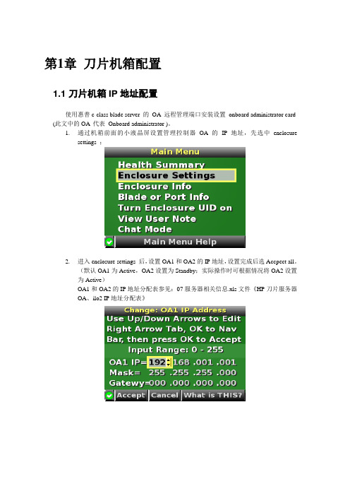
第1章刀片机箱配置1.1 刀片机箱IP地址配置使用惠普c-class blade server 的OA 远程管理端口安装设置onboard administrator card (此文中的OA 代表Onboard administrator )。
1.通过机箱前面的小液晶屏设置管理控制器OA的IP地址,先选中enclosuresettings ;2.进入enclosure settings 后,设置OA1和OA2的IP地址,设置完成后选Accpect all。
(默认OA1为Active,OA2设置为Standby;实际操作时可根据情况将OA2设置为Active)OA1和OA2的IP地址分配表参见:07服务器相关信息.xls文件《HP刀片服务器OA、ilo2 IP地址分配表》1.2 登录机箱IP,进行刀片设置1.2.1 Administrator用户配置1.通过终端的IE6.0 浏览器输入刀片服务器的OA 口的ip 地址:192.168.1.1,进入OA的登录界面,输入机器前方的纸片的出厂OA的用户名和密码登录;2.登录后进入Rack Overview 界面,它把刀片的硬件状态很直观的以图片方式展现,包括设备正反面板图片示意等信息;3.如果是第一次安装刀片服务器机箱,直接进入first time setup wizard ;4.进入Configuration Management,用它可以快速重载一个以前配制好的OA设置;5.Rack and Enclosure Settings,设置机箱的名称、时间、时区等;6.Administrator Account Setup 设置管理员帐户(Administrator 口令:123);Administrator 是管理员权限,可管理所有的刀片服务器,PIN protection 可以启用(目前未启用)、设置PIN Code 来给刀片服务器前面的液晶屏设置密码;1.2.2 Local Users用户配置用户的建立1、以管理员身份登陆到OA系统,在机框列表中选中要控制的机框。
Testo Saveris 2配置指南说明书
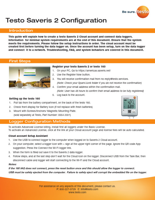
Testo Saveris 2 Configuration To activate Advanced License billing, install first all loggers under the Basic License. To activate an Advanced License, click at the link at your Cloud account page and license fees will be auto calculated.This guide will explain how to create a testo Saveris 2 Cloud account and connect data loggers.Information for minimal system requirements are at the end of this document. Ensure that the system meets the requirements. Please follow the setup instructions in order. The cloud account must becreated first before turning the data logger on. Once the account has been setup, turn on the data logger and connect it to a network. Troubleshooting, FAQ, and system behaviors are covered in this document.Register your testo Saveris 2 or testo 1601. On your PC, Go to https:///2. Use the Register Now button.3. *********************************************************.(Note: Check your Spam/Junk folder if you do not receive the confirmation)4. Confirm your email address within the confirmation mail.(Note: User has 48 hours to confirm their email address to be fully registered)5. Log back to the account.Setting up the testo 1601. Pull tab from the battery compartment, on the back of the testo 160.2. Check front display for Battery Icon (if not replace with fresh batteries)3. Mount with Screws/Anchors/ Magnetic Mounting Plate.(sold separately at Testo, Part Number: 0554 2001)Cloud account Setup Assistant1. Use the USB to connect logger to the computer when logged on to Saveris 2 Cloud account.2. On your computer, select a logger icon with + sign at the upper right corner of the page. Ignore the QR code Appsuggestion. Press the Connect the Wi-Fi logger link.3. When the form is filled out save it to the Saveris 2 data logger.4. Follow steps, and at the last step don’t wait for the Cloud icon on the logger. Disconnect USB from the Task Bar, thendisconnect cable and logger will start connecting to the Wi-Fi and the Cloud account.Notes:If the 160 IAQ does not connect, press the reset button once and this should allow the logger to connect.USB must be safely ejected from the computer. Failure to safely eject will corrupt the embedded file on the logger.To override auto selected Country temperature units setting go to User / User Settings and select the temperature unit from the drop-down selection.•The E-52 error shows that the logger is presently attached to another account.•To remove the logger from its original account, log on, go to Configuration / Wi-Fi data logger, select logger Details in the right column.•Press the Deactivate button at top of the page.•Scroll to the bottom of the page and press the red Remove Data Logger button.•Log out of the account and log back, and if the logger shows up grayed out at the Dashboard listing, click the arrow at the left to delete associated data.•Press shortly the logger button to complete transfer of the delete information.• The logger is now free to be attached to another account.Hot Spot Mode1. Log on to the testo Saveris 2 Cloud account and copy the Account ID (Configuration/Account ID), close the web page.2. Make sure the Wi-Fi adapter is turned on, and the Ethernet cable is pulled out.3. Press the logger button for more than 3 seconds to get LED into continuous green blinking. CONF message on thelogger display confirms the hot spot connection.4. On the computer at Wi-Fi connections connect to Testo Saveris 2 network.5. Open browser and enter 192.168.1.1 at the URL line.6. Fill the form and save, there will be confirmation message on the logger screen.7. A steady Cloud icon on the display indicates connectionNote:USB must be safely ejected from the computer. Failure to safely eject will corrupt the embedded file on the logger. USB Method (for connection to PC using Microsoft Windows OS Only)1. Copy Account ID from your testo Saveris 2 Cloud account (Configuration / Account ID)2. Logger USB connection – open WifiConf.pdf file3. Insert account ID to the form field, fill in name of the network (SSID) and network password. Save configuration(green button) to the logger using Windows File Explorer. Make sure that .xml file is saved to the Saveris 2 drive, not any other folder on your computer.4. Disconnect USB from the Task Bar, then disconnect cable.5. A steady Cloud icon on the display indicates connection to the Cloud website.Note:USB must be safely ejected from the computer. Failure to safely eject will corrupt the embedded file on the logger.testo Saveris 2 / testo 160 work only on 2.4 GHz Wi-Fi. Be sure to select a 2.4 GHz Wi-Fi network.Note: In most institutions, IT permission to install is required, especially on high security networks.NOTE: The MAC Address for the device can be found on the back label. Please keep the MAC Address available.The following browser and router ports must be open:• Browser (Microsoft Edge, Firefox, Google Chrome, Safari): MQTT Port 443 (https)• Router:Port 8883 TCP Secure MQTT (Message Queue Telemetry Transport over SSL)Port 123 UDP Network Time Protocol (NTP)Port 53 TCP Domain Name SystemPort 53 UDP Domain Name SystemCan the Wi-Fi data logger be connected to the PC using any USB cable?• We recommend that you use the USB cable supplied with the Wi-Fi data logger to guarantee stable data transmission.Longer USB cables are suitable for the power supply only.Can the Wi-Fi data logger also be used in networks with WPA2 Enterprise encryption?• testo 160 data loggers can be used in networks with the following WPA2 Enterprise encryption methods.WPA2 Enterprise: EAP-TLS, EAP-TTLS-TLS, EAP-TTLS-MSCHAPv2, EAP TTLS-PSK, EAP-PEAP0-TLS, EAP-PEAP0-MSCHAPv2, EAP-PEAP0-PSK, EAP-PEAP1-TLS, EAP-PEAP1-MSCHAPv2, EAP-PEAP1-PSK, WPA Personal, WPA2 (AES), WPA (TKIP), WEPThe XML configuration file is not being applied by the Wi-Fi data logger, what can I do?• Depending on the operating system, there may be difficulties with the data transfer if the configuration file name has been changed. Leave the default file name.The humidity sensor has been stored at a high temperature (> 30 °C) and in very high humidity (> 80% RH) for a long period of time, what can I do?• The sensor requires a long period of time to regenerate itself again. This process can be accelerated by storing the sensor in a well-ventilated location at a high temperature(> 30 °C} and in low humidity(< 20% RH) for at least 12 hours.The Wi-Fi data logger’s wireless connection to the access point was interrupted, what can I do?1. Press the control key on the Wi-Fi data logger to start searching for a Wi-Fi connection manually.2. Change the alignment or position of the Wi-Fi data logger or the access point (Wi-Fi router).Signal Description LED flashes green every 30 seconds (IAQ)Normal stateLED flashes green at one-second intervals (for 5 min, then 1 long red flash) Configuration mode (hotspot) - press button > 3 secLED flashes green every 200 ms (for 10 seconds)Configuration app: During hotspot mode pressbutton < 3 secLED gives 2 red flashes Connection to Wi-Fi failed (incorrect SSID, In-correct SSID password, incorrect account ID orincorrect account password, attempt to log the160IAQ into the testo Saveris 2 Cloud.If XML is correct, LED gives 1 long green flashIf XML is incorrect, LED gives 3 red flashesConfiguration via USB/PDFLED gives 2 green flashes Connection to Wi-Fi and Cloud successful LED gives 1 long red flash Alarm activated due to limit value violationLED gives 5 green flashes Reset Wi-Fi data logger to factory settingsPress key > 20 secLED gives 1 green flash (measurement data col-lected)Send measurement data to the testo Saveris 2 Cloud (website): press key < 3 secLED gives 4 red flashes Batteries expiredLED flashes alternately green and red Firmware update via USB or wirelessThe error codes can be read out using a web browser via a smartphone/tablet or PC. Press the probe button for 3 seconds. Then enter the following IP address 192.168.1.1 in the web browser.The Wi-Fi data logger (160 IAQ) is displaying error code E03, E04, E05 or E09, what can I do?• An error has occurred in the Wi-Fi data logger. The error will automatically be corrected by the firmware of the Wi-Fi data logger. After a few seconds, the error code should no longer be displayed, you do not need to do anything.The Wi-Fi data logger (160 IAQ) is displaying error code E12, what can I do?• The configuration file WifiConfig.xml indicates an error. Use the Quick Start Guide to create a new configuration file and save this on the Wi-Fi data logger.The Wi-Fi data logger (160 IAQ) is displaying error code E12, what can I do?• The configuration file WifiConfig.xml indicates an error. Use the Quick Start Guide to create a new configuration file and save this on the Wi-Fi data logger.The Wi-Fi data logger (160 IAQ) is displaying error code E23, what can I do?• The most common reason for this error is low battery. Insert new batteries into the Wi-Fi data logger.• If this does not solve the problem: Reset the Wi-Fi data logger to its factory settings. To do this, press and hold down the control key for> 20 s until the display goes blank. If the error code continues to be displayed, then there is a hardware problem. Please contact our Customer Service.The Wi-Fi data logger (160 IAQ) is displaying error code E26, what can I do?• The access point (Wi-Fi router) has no connection to the internet. Check the access point’s internet connection.• The routing within the network infrastructure is not working, check whether too many terminal devices are logged into the access point.The Wi-Fi data logger (160 IAQ) is displaying error code E32, what can I do?The Wi-Fi data logger has not obtained an IP address. There are 2 possible reasons for this error:• The network password is incorrect. Check the password of the Wi-Fi network. Use the Quick Start Guide to create a new configuration file with the correct password and save this on the Wi-Fi data logger.• The access point (Wi-Fi router) has a MAC filter or does not permit the integration of new devices. Check the settings for the access point.The Wi-Fi data logger (160 IAQ) is displaying error code E35, what can I do?• The Wi-Fi data logger has not received any reply to its test ping from the access point (Wi-Fi router). Make sure that a ping to the gateway is allowed within the access point configuration.The Wi-Fi data logger (160 IAQ) is displaying error code E36, what can I do?No DNS available or accessible. Contact the operator of the Wi-Fi network.The Wi-Fi data logger is displaying error code E41, what can I do? The Wi-Fi data logger cannot obtain any current time from a time server ().• The access point (Wi-Fi router) has no connection to the internet. Check the access point’s internet connection.• The NTP port (123/UDP) of the access point (Wi-Fi router) is not open. Check whether the NTP port (123/UDP) is opened.The Wi-Fi data logger (160 IAQ) is displaying error code E51, what can I do?The Wi-Fi data logger was not able to connect to the testo Saveris 2 Cloudd.• If the Wi-Fi data logger has already been connected to the testo Saveris 2 Cloud and this connection is suddenly no longer possible: The testo Saveris 2 Cloud servers are not currently accessible. The servers will be monitored and should be accessible again within a few hours.• If the Wi-Fi data logger has not yet been connected to the testo Saveris 2 Cloud: The TCP ports (1883 or 8883) of the access point (Wi-Fi router) are not open. Check whether the TCP ports (1883 or 8883) are open in both directions.The Wi-Fi data logger (160 IAQ) is displaying error code E52, what can I do?• The Wi-Fi data logger could not log into the testo Saveris 2 Cloud because it is already logged into another account.Please log the Wi-Fi data logger out of the existing account first.The Wi-Fi data logger (160 IAQ) is displaying error code E63, what can I do?The Wi-Fi data logger could not send any data to the testo Saveris 2 Cloud.• The internet connection was interrupted during the transmission. Check whether there is a stable connection from the Wi-Fi data logger to the access point (Wi-Fi router). Check the access point’s internet connection. The data will be transferred during the next communication cycle. Alternatively: Initiate data transmission manually by pressing the control key on the Wi-Fi data logger.• The testo Saveris 2 Cloud server was not able to process the request for data storage. The servers will be monitored and should be accessible again within a few hours.The Wi-Fi data logger (160 IAQ) is displaying error code E69, what can I do?• The Account ID contained in the configuration file is missing or is not valid. Create a new configuration file and save this on the Wi-Fi data logger.• An attempt was made to log the testo 160 E Wi-Fi data logger into the testo Saveris 2 Cloud without any external probes connected. Connect the required external probes before logging inThe Wi-Fi data logger (160 IAQ) is displaying error code E75, what can I do?• A firmware update for the Wi-Fi data logger failed.• The internet connection was interrupted during the transmission or the data was not received intact by the Wi-Fi data logger for other reasons. Check whether there is a stable connection from the Wi-Fi data logger to the access point (Wi-Fi router). Check the access point’s internet connection. The data will be transferred during the next communication cycle.• Alternatively: Initiate data transmission manually by pressing the control key on the Wi-Fi data logger.The Wi-Fi data logger (160 IAQ) is displaying the warning message Err AccountlD, what can I do?• The Account lD contained in the configuration file is not valid.• Use the Quick Start Guide to create a new configuration file and save this on the Wi-Fi data logger.The Wi-Fi data logger (160 IAQ) is displaying the warning message no AccountlD, what can I do?• There is no AccountlD in the configuration file.• Use the Quick Start Guide to create a new configuration file and save this on the Wi-Fi data logger.The Wi-Fi data logger (160 IAQ) is displaying the warning message no License, what can I do?• The Wi-Fi data logger cannot be logged in because the number of Wi-Fi data loggers permitted to log in has been exceeded or your testo 160 license has expired.• Log off another Wi-Fi data logger, extend or renew your testo 160 license.The Wi-Fi data logger (160 IAQ) is displaying the warning message not Active, what can I do?• The Wi-Fi data logger has been deactivated. It is not storing, and therefore not sending, any measurement data to the testo Saveris 2 Cloud.• Activate the Wi-Fi data logger (under Configuration --> Wi-Fi data logger) when the Wi-Fi data logger needs to store and send measurement data again.Testo Data Loggers will operate under free Basic License with limitations as listed at the table below.Register now: https:///。
ERPMRP管理(sunlike) ONLINE ERP 硬件配置建议

ERPMRP 管理(sunlike) ONLINE ERP硬件配置建议硬件建议配置方案以下建议仅做为参考使用,实际配置请参照现况和企业要求及预算来修改,如有任何疑问请联系珠海研发总部硬件配置建议一(高性能配置)1、服务器端配置:(1)IS 网路服务器型号:HPProliantDL585G2(413928-AA1)(2)SQL 专用服务器型号:HPProliantDL585G2(413930-AA1)(3)路由器、交换机、防火墙、UPS 路由器型号:CISCO3745外部:32MB、64MB,128MB 可选工作温度:32 到104°F(0 到40°C)适用环境非工作温度:-40to185°F(-40to85°C) 相对湿度:5-95%,无冷凝工作高度:最高6500 英尺(2000 米),每升高1,000 英尺降低1C交流到直流电源,最高230 瓦(5V、3.3V、12V、-12V)可选装其他电源,最高590 瓦(交流输入):交流-直流电源(5V、3.3V、12V、-12V、-48V,功率为360 瓦)电源输ft:12V@12A、5V@25A、3.3V@18A、-12V@2.5A、(可选-48V@7.5A)100 到240VAC47-63 赫兹输入电流:5Amax@100VACUL1950CAN/CSA-C22.2No.950认证EN60950IEC60950TS0015.25x17.25x15 英寸尺寸(高x 宽x 深)重量32 磅性能:225KppsEMC(电磁兼容性):FCCPart15ICES-003ClassAEN55022ClassA其他性能CISPR22ClassA AS/NZS3548ClassA VCCIClassAFCS 上所支持的接口:串口,2-端口串行WIC1 和2 端口T1/E1CSU/DSUVWIC1 端口56KCSU/DSUWIC4和8 端口同步/异步串行NMHSSINM;交换机型号:CISCOWS-C6506(1300AC)防火墙型号:CISCOPIX-535-FO-BUN1、服务器端配置:(1)IS 网路服务器型号:HPProliantDL585G2(418550-AA1)(2)SQL 专用服务器型号:HPProLiantDL580G4(403413-AA1)(3)、路由器、交换机、防火墙、UPS 路由器型号:CISCO3725CISCO3725 基本特征路由器类型模块化接入路由器固定的广域网接口 1 端口双绞线FE1 端口多模光纤FE固定的局域网接口两个10/100 快速以太网端口控制台端口:1 个(最高为115.2kbps)其他端口辅助端口:1 个(最高为115.2kbps)扩展模块16 和36 端口EtherSwitch 模块处理器RISC128MB(SDRAM 默认)---可扩展到256MB闪速内存内存内部:32MB(默认),可扩展到128MB外部:32MB、64MB,128MB 可选工作温度:32 到104°F(0 到40°C)非工作温度:-40to185°F(-40to85°C)适用环境相对湿度:5-95%,无冷凝工作高度:最高6500 英尺(2000 米),每升高1,000 英尺降低1C交流到直流电源,最高135 瓦(5V、3.3V、12V、-12V)可选装其他电源,最高495 瓦:交流到直流电源(5V、3.3V、12V、-12V、-48V,功率为360 瓦)电源输ft:12V@5A、5V@21A、3.3V@12A、-12V@2A、(可选-48V@7.5A)100 到240VAC47-63 赫兹输入电流:2Amax@100VAC;1Amax@UL1950CAN/CSA-C22.2No.950认证EN60950IEC60950TS001交换机型号:CISCOWS-C3550-24-EMI 防火墙型号:CISCOPIX-525-UR-BUN CISCOWS-C3550-24-EMI 主要参数 交换机类型 网管交换机 内存32MBDRAM 和 8MB 闪存 传输速率(Mbps )10Mbps/100Mbps/1000Mbps IEEE802.1x 、 IEEE802.3x 、 IEEE802.1D 、 IEEE802.1p 、 IEEE802.1Q 、 网络标准 IEEE802.3、IEEE802.3u 、IEEE802.3ab 、IEEE802.3z 端口数量24 个 10/100 端口+2 个 1000BaseX 端口 传输模式支持全双工 配置形式 可堆叠 交换方式存储-转发 背板带宽(Gbps)8.8Gbps VLAN 支持 支持 CISCOPIX-525-UR-BUN 主要参数 设备类型 企业级防火墙 并发连接数 280000 网络吞吐量370Mpps 安全过滤带宽100MB 用户数限制 无限制 入侵检测 DoS 、IDS UL,C-UL,TUV,IEC950,UL-1950 标 准 : 第 三 版 ,TUVEN60950 : 第 二 版 , 安全标准Am.1-4,IEC-950/VDE-0805EN-60-950 标准:支持。
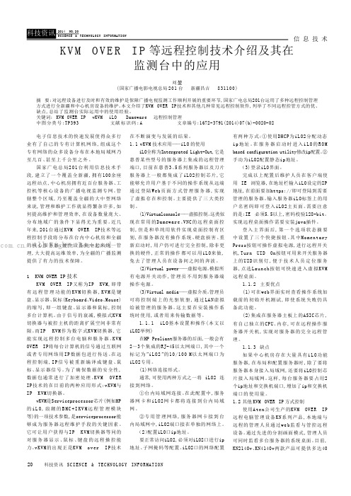
KVM OVER IP等远程控制技术介绍及其在监测台中的应用
信 息 技 术20科技资讯 SC I EN C E & TE C HN O LO G Y I NF O R MA T IO N电子信息技术的快速发展使得众多行业有了自己的专有计算机网络,组成这个专有网络的众多设备分布在本地局域网乃至几百、甚至上千公里之外。
国家广电总局201台利用信息技术手段,建立了一个覆盖全新疆,拥有100余座远程站点,中心机房拥有近百台服务器、工控机等核心设备的广播电视监测专网。
管辖整个区域,乃至覆盖全疆的大中型网络来说,管理和维护工作就显得繁杂许多,如何提高维护和管理效率,在设备数量庞大、分布地域广的条件下显得尤为重要。
近几年来,201台通过KVM OVER IP技术等远程控制手段将分布在台内中心机房和全疆的核心服务器、硬件设备集中起来统一管理,大大提高运维效率,为全疆的广播监测提供了有力的技术保障。
1 KVM OVER IP 技术KVM OVER IP又称为IP KVM,即带有远程管理功能的K V M 切换器,K V M 是键盘、显示器、鼠标(Keyboard、Video、Mouse)的缩写,即一组键盘、显示器和鼠标,控制多台计算机。
由于信号的衰减,模拟式KV M 切换器与被控主机的距离扩展空间非常有限。
而IP K VM 作为数字式KV M切换器,它能实现远程控制多台电脑和服务器。
K V M OVER IP将每台计算机的信号通过互联网或者专用网络用I P 数据包进行传送。
在远程控制端,I P 信号被重新编译成键盘、鼠标、显示器信号。
为了确保数据的安全性,数据包通常进行了加密处理。
K V M O V E R IP技术的在目前的两种应用形式:vKVM与IP K VM切换器。
vKVM是Serviceprocessor芯片(例如HP 的i L O ,浪潮的B M C +I K V M 远程管理模块等)的一项技术参数,是serviceprocessor能够成为服务器远程维护手段的关键因素。
HP ProLiant DL365 第五代(G5)服务器 说明书

采用全新的AMD 四核处理器,高达32GB 的DDR 2-667MHz 内存,PCI-E 技术为两路处理器系统提供了强劲的IO 性能。
在1U 高的服务器中,支持6个2.5英寸的SAS 或SATA 的硬盘。
这款服务器非常适合运行多种要求不断扩充处理性能的应用程序。
借助远程管理功能实现虚拟的现场控制与管理,包括电源的打开与关闭,通过图形化的控制终端,可以将远端的远程介质如光驱、软驱映射给服务器,从而实现虚拟设备的使用。
通过机柜的优化设计,在一个超高密度的机箱中,容纳了冗余的风扇,冗余的电源以及其它多种可升级的选件。
全新特性HP ProLiant DL365 G5所使用的处理器是最新的AMD 四核处理器。
高性能•两路AMD 皓龙四核处理器2300•PC5300 DDR2-667增强的ECC 内存技术,最多支持大32GB ,8个内存插槽•全新的SmartArray E200i 以及SmartArray P400i 磁盘阵列卡,可以为用户提供高性价比和高性能的磁盘IO特性HP ProLiant DL365第五代(G5)服务器DL365 G5是一个基于机柜优化模式的高密度机柜服务器,可应用于数据中心和多种应用环境,在1U 高的机箱当中,集成了优异的远程管理功能和高处理性能。
•支持2.5英寸SAS 和SATA 硬盘,可扩展至6块,最大存储容量:SAS 硬盘容量876GB ,SATA 硬盘容量720GB 高扩展性:•两个PCI-E 插槽,一个全长一个半长•4个USB 接口,1个前置,1个内置,2个后置管理特性•标准配置带有集成的远程控制功能iLO2•前置的可滑动的状态显示面板,可直观查看系统组件状态•ProLiant 精华基础软件包可选附件•可选的冗余电源模块和风扇模块•可选的电缆管理导向臂。
便于管理与维护设计与连接•冗余的风扇•前置的显示器端口•双端口多功能千兆以太网卡•通用的机柜安装滑轨,可以应用于方形或圆形的多种定位孔的机柜产品编号说明447598-AA1(1) 个AMD Opteron™ (皓龙™)处理器2352 (2.1GHz,75瓦),标配1GB (2 x 512MB)、PC2-5300 DDR2 DIMM (667MHz),机架式(1U)标准配置处理器AMD Opteron™ (皓龙™)处理器2354 (2.2GHz,75瓦)AMD Opteron™ (皓龙™)处理器2352 (2.1GHz,75瓦)内存类型PC2-5300 DDR2 DIMM (667MHz)取决于产品型号标配(基本机型)1GB (2 x 512MB)最大32GB (8 x 4GB)注:DIMM必须依容量递减安装,最大的DIMM安装在距每个处理器最远的插槽内。
HP ProLiant DL320第5p代(G5p)服务器 说明书

借助远程管理以及iLO-2所提供的虚拟KVM 功能,实现了最佳的远程管理与控制。
达到了企业级的管理水平。
可安装1到2个价格便宜的SATA 硬盘,并可以升级为热插拔的SAS 硬盘。
使得DL 320 G5可以充分满足数据中心的需求。
高性能:•处理器既支持最新的Intel 3000系列的四核处理器,也可以支持3000系列的双核处理器,更可以支持物美价廉的Intel 酷睿2 E 系列处理器,如果预算较低,还可选Intel 赛扬420处理器•内存采用PC2-6400 DDR2,4个内存插槽,最大容量可达8GB•标准配置2个3.5寸SATA 硬盘,通过升级可以支持最多4个热插拔SATA 或SAS 硬盘•集成2端口SATA 硬盘控制器,可以支持RAID 0,1•集成NC326i双端口千兆网卡HP ProLiant DL320第5p 代(G5p)服务器HP ProL iant DL 320 G5P 是一款企业级单路处理器的机柜服务器,具有非常好的性价比。
价格是入门级服务器价位,高度为1U ,运行单一应用非常理想,非常适合用于网络基础架构应用以及WEB 服务器等应用。
扩展能力:•具有两个扩展插槽:一个全长的PCI-E X8插槽,一个半长半高的PCI-E X8插槽•5个USB 插槽,2个前置,1个内置,2个后置管理性:•集成iLo2远程管理功能•精华软件包,SIM 管理包,Smartstart•前置状态指示灯用于显示健康状况,UID 指示灯适用:•企业级数据中心IT 基础架构,或专项应用•需要1U 高度,专项应用的企业•对服务器管理有需求,需要远程管理与控制。
物理空间要求较少的企业HP ProLiant DL320第5p代(G5p)服务器产品编号说明445434-AA1英特尔®至强®四核处理器3210 (2.13GHz,8MB二级高速缓存,95瓦,1066MHz前端总线),8MB二级高速缓存,2 GB (标配)到8 GB (最大) ECC PC2-6400无缓冲DDR2 SDRAM内存,机架式445432-AA1英特尔®至强®双核处理器3110 (3.0GHz,6MB二级高速缓存,65瓦,1333MHz前端总线),6MB二级高速缓存,1GB (标配)到8GB (最大) ECC PC2-6400无缓冲DDR2 SDRAM内存,机架式445431-AA1英特尔®至强®四核处理器X3320 (2.5GHz,6MB二级高速缓存,95瓦,1333MHz前端总线),6MB二级高速缓存,2 GB (标配)到8 GB (最大) ECC PC2-6400无缓冲DDR2 SDRAM内存,机架式标准配置处理器英特尔®至强®四核处理器X3350 (2.66GHz,12MB二级高速缓存,95瓦,1333MHz前端总线)取决于产品型号注:仅通过CTO可用。
HP ILO2配置手册
HP ILO2网络管理功能配置手册一、iLO2的配置iLO2的配置过程,分为服务器端和客户端的配置。
首先我们需要为服务器的iLO2端口设置一个IP地址,可以手动设置或者通过DHCP服务器分配。
1.服务器端的配置1)DHCP分配通过DHCP获取IP地址的方法很简单,只需通过网线将服务器后端的iLO2接口和DHCP 服务器连通即可。
图表-1惠普服务器后端的iLO2接口2)手动设置为iLO2接口设置静态IP我们需要以下的步骤:服务器加电后,当屏幕出现“Intergrated Light-Out 2 Advanced Press [F8] to Configure”提示的时候按F8键,进入iLO2的高级设置。
图表-2iLO2配置界面因为iLO2默认情况下是设置为通过DHCP获取IP地址,所以如果我们要设置静态IP 的话首先要关闭iLO2的DHCP功能。
在“Network”菜单中选择“DNS/DHCP”,使用空格键将DHCP Enable状态改为“OFF”,然后按F10键保存。
图表-3关闭DHCP功能关闭DHCP功能之后选择“Network”菜单中的“NIC and TCP/IP”,进入网络配置界面,在这里我们可以设置iLO2接口的IP地址、子网掩码和网关。
设置完毕后还是按F10来保存,需要注意的是如果不在开始关闭iLO2的DHCP功能这里是不能设置的。
在这里我们将IP地址设置为192.168.1.2/24。
图表-4设置IP地址在“Setting”菜单中可以进行一些其他的iLO2设置,这些设置保持默认配置即可。
至此服务器端的配置就完成了,设置非常简单。
通过iLO2的配置界面我们还可以进行添加管理帐户、恢复出厂配置等操作。
图表-5可以添加管理帐户当客户端通过Web方式连接到iLO2端口时,需要输入管理帐户的用户名和密码,默认情况下用户名为“Administrator”,密码在服务器顶盖的标签上也会提供,注意大小写是敏感的。
HP iLO使用指南
</>hpiLO->
</>hpiLO-> show -l all /map1/firmware1
status=0
status_tag=COMMAND COMPLETED
/map1/firmware1
Targets
Properties
version=1.82
date=03/31/2010
HP系列iLO的特点有:
1. 不支持串口,命令行操作不方便。这点比Sun差不少,Sun设备每款SP都支持串口。
2. WEB管理比较丰富,从IE升级Firmware很方便,对WEB客户端IE比较依赖。
3. 支持Web Console以及程虚拟光驱软驱。这些功能有当然好,但不是必需的。
4. iLO的串口与物理机器串口混用,对外屏蔽了不少iLO技术细节。
iLO缺省终端设置是9600,8,n,1,-)
建议使用iLO终端设置是115200,8,n,1,-)
原因是iLO卡引导时候使用了115200的波特率
iLO上相关的逸出键(escape key,两个相邻逸出键最大间隔为1秒)的含义
ESC ( invokes the serial CLI connection.
status=0
status_tag=COMMAND COMPLETED
Resetting iLO.
CLI session stopped
</>hpiLO-> reset /system1
status=0
status_tag=COMMAND COMPLETED
Resetting server.
CMU安装配置手册
CMU安装配置手册1.前言表1:术语表2:符号定义2.准备安装本章描述了安装HP的集群控制单元(Cluster Management Unit)CMU之前的要求,这个指南包括如何检查将要安装CMU的设备硬件、软件、磁盘空间等信息。
本章同时细述了对主磁盘的要求,主磁盘必须位于阵列中的计算机节点上。
本章对系统的详细要求适用于所有支持的操作系统。
2-1 CMU套件分发CMU套件按操作系统使用CD-ROM分发,便于用户直接用CD-ROM安装到硬盘。
CMU的Linux版本使用RPM(RedHat Package Manager)格式。
2-2 CMU CD-ROM的内容CD-ROM包括以下部分:文档CD-ROM的./Documentation目录提供了pdf格式的文档。
文档中有两个指南:●CMU安装指南●CMU用户指南阅读pdf文件需要acrobat reader软件,adobe网站提供。
CMU安装完成后,文档将位于管理节点的/opt/cmu/doc。
以下文件在CD-ROM上可以找到:●Readme.txt:光盘目录及其它信息●Release.txt:记录版本和所有软件修改●Copyright.txt:记录版权信息确信在实际安装前从光盘上看到这些文件,每种操作系统的安装教学在本指南的以下章节提供。
软件所有的CMU服务器安装要素do在CMU CDROM里。
目录./documentation下保存安装手册和用户手册目录./Linux保存X86和X86-64的安装套件。
●CMU-<version>-i686.rpm (CMU V3.2 for X86 and X86-64)●Bootp-2.4.3-7.i386.rpm (bootp daemon for X86 and X86-64 or nonRedHat5 x86_64 distribuTions)●Redhat5/bootp-2.4.3-7.x86_64.rpm for Redhat5 X85_64目录./Linux-IA64包含IA64的安装套件。
HP-iLO2-iLO3管理口配置及使用手册
HP integrated Light-Out 2 远程管理卡(iLO2)操作指南QQ1656749CONTENTSCONTENTS (2)1.ILO2远程管理卡简介 (3)1.1.I LO2是什么 (3)1.2.I LO2的使用模式 (3)2.ILO2的基本设置 (4)2.1.I LO2的网络连接方式 (4)2.2.I LO2的网络及用户设置 (4)3.使用ILO2管理远程服务器 (9)3.1.I LO2所需的浏览器设置 (9)3.1.1.浏览器版本 (9)3.1.2.浏览器的ActiveX设置 (9)3.2.使用浏览器访问I LO2 (11)3.3.使用浏览器管理I LO2 (12)3.3.1.升级iLO2的Firmware (12)3.3.2.升级iLO2的License (13)3.3.3.用户管理 (13)3.3.4.网络及其他设置 (14)3.4.使用I LO2查看系统信息和日志 (16)3.5.使用I LO2的远程控制台功能 (18)3.6.使用I LO2的虚拟介质功能 (20)3.6.1.虚拟电源 (20)3.6.2.功率调节器 (21)3.6.3.虚拟介质 (22)4.ILO2远程管理卡特性总结 (24)1. iLO2远程管理卡简介1.1.iLO2是什么iLO(Integrated Lights-Out)是HP独有的服务器远程管理技术.如今的商业要求需要服务器能在任何时间和地点都能提供24小时不间断的管理能力. 公司不再需要为雇用的主管提供奢侈的远程场所,或为了远程服务器的维护而花费更多时间。
为了满足这些日益增长的响应需求,需要服务器具有易用的远程管理功能.为此, HP发展了Integrated Lights-Out技术。
Integrated Lights-Out 是一个可通过任何服务器状态来管理主机服务器的自主管理分系统:操作系统加载前的初始开机测试,,即使系统失败它仍具备此功能. 实际上, Integrated Lights-Out 是一个计算机内部的自主计算机系统:高度优化的体系结构,包括特有的使用单独指令集和数据缓存的RISC 处理器,内存子系统和以太网控制器,Integrated Lights-Out 提供一个可以让管理员控制的具有图形方式的远程管理控制平台,实现对服务器在任意时间和在任意操作系统下的图形方式控制。
- 1、下载文档前请自行甄别文档内容的完整性,平台不提供额外的编辑、内容补充、找答案等附加服务。
- 2、"仅部分预览"的文档,不可在线预览部分如存在完整性等问题,可反馈申请退款(可完整预览的文档不适用该条件!)。
- 3、如文档侵犯您的权益,请联系客服反馈,我们会尽快为您处理(人工客服工作时间:9:00-18:30)。
HP Systems Insight Manager(HP SIM),是HP公司推出的,偏重于HP服务器、存储的硬件管理的一套软件。
把这套软件装在一台HP称之为 CentralManagement Server(CMS)的服务器上(不考虑性能,用个台式机也行),你就能监控网络中所有HP及非HP服务器,存储设备,交换机等等的硬件健康状态,性能状况等;在硬件故障时自动发送报警邮件;还可以产生统计报告。
HP SIM采用如下流程来实现上述目标:首先要发现被管理的设备。
HP SIM新安装好后默认会扫描CMS同一个网段(1~255),并把找到的设备加入到监控清单中,这里使用的协议是IP,也就是去ping找到设备之后,会进行识别。
HP SIM会尝试用SNMP,Desktop ManagementInterface(DMI),Web-Based Enterprise Management(WBEM),以及HTTP这些协议与目标设备通信,确定它所支持的协议。
然后就用目标设备所支持的协议,抓取管理信息,比如设备类型,型号,健康状况等等。
这个过程称之为Data Collection。
在Discovery-->Identify-->Data Collection这个三个步骤中,有两个协议的使用最为重要,也最容易出错,就是SNMP和WBEM,我在问题篇中会比较详细的说明。
为了使不同职责的人员分别查看管理各自的设备,HP SIM包含了一个用户和授权的体系,可以分别指定不同用户对SIM的权限。
HP SIM还包含一些插件来丰富它的功能,比如对网卡驱动,主板BIOS固件版本等的检测和管理(VCR),对Windows系统补丁的管理,对服务器性能的管理(PMP),对硬件保修信息的管理(Remote Support Software Manager)等等HP iLOHP iLO 详细介绍一、HP iLO 简介iLO 是一组芯片,内部是vxworks的嵌入操作系统,在服务器的背后有一个标准RJ45口对外连接生产用交换机或者带外管理的交换机。
iLO 全名是 Integrated Lights-out,它是惠普某些型号的服务器上集成的远程管理端口,它能够允许用户基于不同的操作系统从远端管理服务器,实现了虚拟存取和控制,从而进行智能型基础构架和管理。
iLO自己有处理器,存储和网卡,默认网卡配置是DHCP,可以在服务器启动的是欧进入iLO 的ROM based configuration utility 修改 ip, dpch->;static。
服务器买的时候,在面板左侧,会有一个白色的纸吊牌,上面写着iLO 网卡上的DNS name和 Username Password。
请勿随便更改,更改了不要遗失。
iLO的使用很简单.用网线把iLO口和你的LAN switch或者专门的OB(带外管理) switch 相连。
如果你准备让iLO 默认方式工作,你需要有一个 LAN内的DHCP和DNS 服务器存在。
如果你在服务器启动的时候修改dhcp 到static ip,就无所谓了。
在你的笔记本或者pc上,开一个IE(支持java), 然后地址那里书写 iLO DNS name(写在纸吊牌上的,你需要DHCP DNS 服务器在局域网内)。
就可以看到iLO界面了。
或者直接填写iLO的ip地址也可以。
iLO界面除了报告一些硬件信息之外,主要提供了三大类控制:Virtual console, 就是类似pc anywhere 的远程控制了,但是和软件的控制不一样,它是完全硬件级的,哪怕你的服务器没有操作系统,或者硬盘损坏,或者重新启动,都可以完整的进行控制,所以除非更换被管理服务器的硬件,正常的操作都可以用iLO来做,根本不用进入机房。
(当然得保证网络通畅)。
第二类是 Virtual power, 虚拟电源,模拟所有的电源开关动作,比如按住不放,按住就放等等...第三类是Virtual media ,虚拟介质,你可以将pc或者笔记本上的光驱软驱,通过LAN, 虚拟给被管理的服务器。
这个主要是用来安装操作系统,或者传输数据,打补丁之类的。
比如那个被管理服务器是新的,没有操作系统,硬盘也没有作阵列,怎么结合上面的三类控制手段来操作呢?1. 用virtual power重启动服务器2. 用virtual console 远程操作服务器,在服务器启动的POST时候,进入 G4服务器的Smart array 6i Rom based utility 进行阵列配置3. 用virtual console 远程操作服务器,在服务器POST完毕的结束阶段,F9进入系统的BIOS,我们行话叫RBSU 进行配置4. 用virtual media 将我本地笔记本或者pc的光驱虚拟出去,然后在我本地的光驱中,放windows/linux 等的安装盘。
5. 远端的被管理服务器以为自己插了一个usb 光驱,或者软驱,然后按照大家熟悉的正常方式从光盘软盘启动,不过却是用自己本地的光盘(虚拟媒体功能)。
6. 你在virtual console 里面进行和平时一样的安装操作。
有一点要注意,默认的服务器买来,iLO 是不支持图形界面的,也就是说,当你virtual console 里面的远程服务器开始进入windows, X-windows的时候,本地pc,笔记本的IE 就看不出远端的画面了(虚拟KVM功能),你需要向hp购买iLO advanced pack, 即一个iLO serial number, 把这个iLO serial number输入到iLO的一个专门输入注册号的地方,就可以突破这个限制了,不过远端如果是linux,并且是字符界面,就无所谓买不买了(用Serial over LAN功能即可)。
这个输入注册号的地方,在你IE访问iLO 后出现的管理界面的菜单上有的,最后一个。
就这些,HP的iLO目前是x86服务器系统中最理想的技术了,我们比较了好几种同类产品,在标配不加卡的情况下,HP 的管理应该是最好的二、HP iLO 端口的配置开机自检时,按F8键进入 iLO 的设置界面:1、进入 iLO 的设置:在菜单File 下的“Set Defaults”是将所有的设置恢复为出厂值;2、在菜单Network选项中配置网络:分别设置 IP 地址和 DNS。
IP 应在同一个网段中,注意子网掩码的一致。
(只有在 DHCP 被设为 Disable 时,才能设置 IP address/Subnet Mask/Gateway IP address)DNS 的名字在服务器前面带的卡片上,还包括管理员的账号和密码。
如IP 必须是静态的,DHCP 需设置为 OFF。
3、在菜单User选项中可以添加、删除、更改远程访问 User 的密码,权限等;增加用户及编辑用户属性(密码及权限)选择需要编辑的用户及其属性4、在菜单Settings 的选项设置 Keyboard 的属性等,一般都为默认值;5、菜单About为 iLO 的 firmware version固件版本,序列号等一些信息;三、目前支持集成iLO的HP服务器有以下几种:·HP ProLiant DL300/500系列HP ProLiant DL320HP ProLiant DL360HP ProLiant DL380HP ProLiant DL580·HP ProLiant ML300系列HP ProLiant ML350HP ProLiant ML370·HP ProLiant BL刀片服务器系列 p-Class/c-Class注意:HP ProLiant DL100/ML100系列没有iLO,只有IPMI。
HP iLO配置专题1.服务器ilo2口配置:一、如何配置iLO口启动HP DL380,按F8 进入ilo2配置界面关闭DHCP服务后配置IP(我的设置ip:172.16.86.16 掩码:255.255.0.0 网关:0.0.0.0)保存后重启。
2.将IOL2接口用网线连上交换机3.透过IE浏览器访问iLo的IP地址(172.16.86.16),过程中将会提示安装Java的一个软件包,下载并安装。
4.输入用户名Administrator(大写A)和密码,就进入到iLo的远程管理页面了.5.然后去HP的官方网站可以申请到一个为期60天免费试用的License(key 免费60天试用License申请地址:/uploads/ovrd/ovr_l_proliant_0001.html)6.输入License,再submit,OK,搞定了,来试一试吧!二、iLO口启动后造成服务器串口心跳无法启动问题解决由于HP 380G3服务器提供一个远程管理的接口(iLO),这个功能允许用户通过串口访问HP服务器(CLI功能),当iGWB倒换时,促发了iLO的串口通信功能,这样串口就被iLO接管,iGWB就失去了对串口的控制,无法传送串口心跳信息,造成串口心跳中断。
串口心跳中断后,只剩下一条网口心跳,如果网口心跳也中断(如网络发生故障),iGWB出现问题时将不能正常倒换,因此此故障将影响iGWB双机的可靠性。
所以需要关闭CLI功能。
具体操作步骤如下:Power on the server. 服务器重新加电开机Press the F8 key to access the Integrated Lights Out (iLO) ROM Based Setup Utility, when prompted, during System POST. 在BIOS自检到iLO提示时,按F8键,进入iLO的BIOS设置Navigate to Settings -> CLI and press the ENTER key. 进入iLO BIOS的settings选项。
再选CLI,按回车Use the keyboard space bar to toggle the Serial CLI Status field to DISABLED. 使用键盘的空格键,选择CLI的状态为DISABLEDPress F10 to save the setting. 按F10键保存设置Exit the Integrated Lights-Out (iLO) ROM Based Setup Utility. 退出iLO设置三、禁止掉iLO功能后如何启动iLO功能To enable iLO, perform the following:With the server powered off, open the server and locate the Security Override Switch (which may actually be a jumper or a switch.) Refer to the server documentation or the server hood label to identify the position of this switch (or jumper.)Place the switch in the "Security Disabled" position.Reboot the server and watch for the message: "Integrated Lights-Out is disabled." Immediately following this message, iLO will display "Integrated Lights-Out press [F8] to configure." At this point, press [F8] to run the ROM-Based Setup Utility (RBSU).Navigate the RBSU menu to the "Settings" tab and select "Configure."Select to "Enable Lights-Out Functionality."With the server powered off, set the Security Override Switch back to the "Security Enabled" position.。