AVEVA E3D Equipment Modelling TM-1811
维特兰工程有限公司产品说明书
©2016 Whelen Engineering Company Inc.Form No.14961 (010816)A u t o m o t i v e : For warranty information regarding this product, visit /warranty•Proper installation of this product requires the installer to have a good understanding of automotive electronics, systems and procedures.•Whelen Engineering requires the use of waterproof butt splices and/or connectors if that connector could be exposed to moisture.•Any holes, either created or utilized by this product, should be made both air- and watertight using a sealant recommended by your vehicle manufacturer.•Failure to use specified installation parts and/or hardware will void the product warranty.•If mounting this product requires drilling holes, the installer MUST be sure that no vehicle components or other vital parts could be damaged by the drilling process. Check both sides of the mounting surface before drilling begins. Also de-burr the holes and remove any metal shards or remnants. Install grommets into all wire passage holes.•If this manual states that this product may be mounted with suction cups, magnets, tape or Velcro®, clean the mounting surface with a 50/50 mix of isopropyl alcohol and water and dry thoroughly.•Do not install this product or route any wires in the deployment area of your air bag. Equipment mounted or located in the air bag deployment area will damage or reduce the effectiveness of the air bag, or become a projectile that could cause serious personal injury or death. Refer to your vehicle owner’s manual for the air bag deployment area. The User/Installer assumes full responsibility to determine proper mounting location, based on providing ultimate safety to all passengers inside the vehicle.•For this product to operate at optimum efficiency, a good electrical connection to chassis ground must be made. The recommendedprocedure requires the product ground wire to be connected directly to the NEGATIVE (-) battery post (this does not include products that use cigar power cords).•If this product uses a remote device for activation or control, make sure that this device is located in an area that allows both the vehicle and the device to be operated safely in any driving condition.•Do not attempt to activate or control this device in a hazardous driving situation.•This product contains either strobe light(s), halogen light(s), high-intensity LEDs or a combination of these lights. Do not stare directly into these lights. Momentary blindness and/or eye damage could result.•Use only soap and water to clean the outer lens. Use of other chemicals could result in premature lens cracking (crazing) and discoloration. Lenses in this condition have significantly reduced effectiveness and should be replaced immediately. Inspect and operate this product regularly to confirm its proper operation and mounting condition. Do not use a pressure washer to clean this product.•It is recommended that these instructions be stored in a safe place and referred to when performing maintenance and/or reinstallation of this product.•FAILURE TO FOLLOW THESE SAFETY PRECAUTIONS AND INSTRUCTIONS COULD RESULT IN DAMAGE TO THE PRODUCT OR VEHICLE AND/OR SERIOUS INJURY TO YOU AND YOUR PASSENGERS!Warnings to InstallersWhelen’s emergency vehicle warning devices must be properly mounted and wired in order to be effective and safe. Read and follow all of Whelen’s written instructions when installing or using this device. Emergency vehicles are often operated under high speed stressful conditions which must be accounted for when installing all emergency warning devices. Controls should be placed within convenient reach of the operator so that they can operate the system without taking their eyes off the roadway. Emergency warning devices can require high electrical voltages and/or currents. Properly protect and use caution around live electrical connections.Grounding or shorting of electrical connections can cause high current arcing, which can cause personal injury and/or vehicle damage, including fire. Many electronic devices used in emergency vehicles can create or be affected by electromagnetic interference. Therefore, after installation of any electronic device it is necessary to test all electronic equipment simultaneously to insure that they operate free of interference from other components within the vehicle. Never power emergency warning equipment from the same circuit or share the same grounding circuit with radio communication equipment. All devices should be mounted in accordance with the manufacturer’s instructions and securely fastened to vehicle elements of sufficient strength to withstand the forces applied to the device. Driver and/or passenger air bags (SRS) will affect the way equipment should be mounted. This device should be mounted by permanent installation and within the zones specified by the vehicle manufacturer, if any. Any device mounted in the deployment area of an air bag will damage or reduce the effectiveness of the air bag and may damage or dislodge the device. Installer must be sure that this device, its mounting hardware and electrical supply wiring does not interfere with the air bag or the SRS wiring or sensors. Mounting the unit inside the vehicle by a method other than permanent installation is not recommended as unit may become dislodged during swerving; sudden braking or collision. Failure to follow instructions can result in personal injury. Whelen assumes no liability for any loss resulting from the use of this warning device. PROPER INSTALLATION COMBINED WITH OPERATOR TRAINING IN THE PROPER USE OF EMERGENCY WARNING DEVICES IS ESSENTIAL TO INSURE THE SAFETY OF EMERGENCY PERSONNEL AND THE PUBLIC.Warnings to UsersWhelen’s emergency vehicle warning devices are intended to alert other operators and pedestrians to the presence and operation of emergency vehicles and personnel. However, the use of this or any other Whelen emergency warning device does not guarantee that you will have the right-of-way or that other drivers and pedestrians will properly heed an emergency warning signal. Never assume you have the right-of-way. It is your responsibility to proceed safely before entering an intersection, driving against traffic, responding at a high rate of speed, or walking on or around traffic lanes. Emergency vehicle warning devices should be tested on a daily basis to ensure that they operate properly. When in actual use, the operator must ensure that both visual and audible warnings are not blocked by vehicle components (i.e.: open trunks or compartment doors), people, vehicles, or other obstructions. It is the user’s responsibility to understand and obey all laws regarding emergency warning devices. The user should be familiar with all applicable laws and regulations prior to the use of any emergency vehicle warning device. Whelen’s audible warning devices are designed to project sound in a forward direction away from the vehicle occupants. However, because sustained periodic exposure to loud sounds can cause hearing loss, all audible warning devices should be installed and operated in accordance with the standards established by the National Fire Protection Association.Safety FirstThis document provides all the necessary information to allow your Whelen product to be properly and safely installed. Before beginning the installation and/or operation of your new product, the installation technician and operator must read this manual completely. Important information is contained herein that could prevent serious injury or damage.WARNING: This product can expose you to chemicals including Methylene Chloride which is known to the State of California to cause cancer, and Bisphenol A, which is known to the State of California to cause birth defects or other reproductive harm. For more information go to .Installation Guide:Legacy® R65 WeCan® Lightbar51 Winthrop RoadChester, Connecticut 06412-0684Phone: (860) 526-9504Internet: Salese-mail:*******************CustomerServicee-mail:*******************®ENGINEERING COMPANY INC.IMPORTANT! The lightbar must be a minimum of 16" from any radio antennas.NOTE: There may be a roof support member that spans the distance between the driver’s and passengers side. DO NOT DRILL THROUGH THIS MEMBER! Adjust the location until the holes can be drilled without contacting this support member.Strap Mounting:1.Install the mounting bracket to the mounting foot using the supplied5/16 FLAT WASHERS and 5/16 - 18 ELASTIC STOP NUTS (Fig. 1).Do NOT install the optional spacers yet.2.Place the bracket into the track on the bottom of the extruded base ofthe lightbar and twist it into position (Fig. 2).Permanent Mounting:Caution:Permanent mounting of this product will require drilling.It is absolutely necessary to make sure that no other vehicle components could be damaged by this process. Check both sides of the mounting surface before starting. If damage is likely, select a different mounting location.1.Install the mounting foot to the lightbar following steps 1 thru 4 of “Strap Mounting”.2.Position the lightbar onto the vehicle in its exact mounting location and mark the location of the mounting holes onto the mounting surface using the mounting feet as templates.If the permanent mounting holes in the mounting feet are difficult to access, you can use the measurements shown here to mark off and drill the mounting holes. You will also need to measure the distance between the mounting feet for your application since lightbar width will depend on the lightbar you are mounting.3.Remove the lightbar and drill the 4 mounting holes.4.Install the lightbar using the supplied 1/4 - 20 Phillips Pan Head Metal Screw, 1/4” Internal Tooth Lock Washer and 1/4 - 20 X 7/16 Hex Nut.IMPORTANT! It is the responsibility of the installation technician to make sure that the installation and operation of this product will not interfere with or compromise the operation or efficiency of any vehicle equipment! Before returning the vehicle to active service,visually confirm the proper operation of this product, as well as all vehicle components/equipment.RED = (+) POSITIVE BLACK = (-) NEGATIVEGREEN = COMUNICATIONSGREY = COMUNICATIONS1312LIGHTHEAD OPTIONSHALF TIR TAKEDOWNFULL TIR TAKEDOWNTIR ALLEY LIGHT01-0688130-__R65 WC LEGACY LIGHTBAR, BLUE/AMB 48"01-0688130-__01-0688130-__11-387277-044BASE, EXTRUDED 44.4" MACHINED LOW PROFILE LTBAR 11-387385-050R65 WC LEGACY LIGHTBAR, BLUE/AMB 54"R65 WC LEGACY LIGHTBAR, BLUE/AMB 59"11-387385-0551GROMMET, SPECIAL TO BE MOLDED 1.562"21-11245004-11PLUG, VENT.750 DIA HOLE LIGHTBAR21-7263998-002BRACKET, BULKHEAD LENS MOUNT LOW PROFILE LIGHTBAR 07-26D 863-0006INSULATOR, I.O./EXTRUSION DIE CUT PLASTIC LPL 38-0244488-002ASSY, PCB I/O BOARD LEGACY LTBAR02-0187275-001ASSY,CABLE INPUT 2/C 10 GA 17' LEGACY SOLO 46-0747027-171ASS'Y, CABLE 2/C 20 GA 17' STRIP 1.75"/770904 SCKT 46-0743442-021CABLE CLAMP, 1/2"D, 1/2"W .203" MTG HOLE, BLACK 26-0115037-081NUT, 10-24 CAD PLATED WHIZ OR STEEL ZINC PLATED 13-104111-0631TY WRAP, 6" BLACK26-0215001-061ASSY, CORNER L-FRONT/R-REAR BA R65 LEGACY 01-026G 753-21ASSY, CORNER R-FRONT/L-REAR BA R65 LEGACY 01-026G 754-21BRACKET, I/O ANCHOR LOW PROFILE LIGHTBAR 07-26D 865-000SUB ASSY, FULL TIR TAKE-DOWN LEGACY 01-026E 388-30SUB ASSY, HALF TIR TAKE-DOWN LEGACY01-0246796-30BRACKET, CLAMP SUPPORT HALF DIRECTIONAL LEGACY 07-244477-000SCREW, 6-32 X 1/2 PPHMS SEMS W/IT LOCK WASHER 14-062216-081BASE, MACHINED 50.228" LEGACY LIGHTBAR 1SCREW, 10-24 X .875"TX PHD SWEDGE FORM 1/4" LEAD 5/8"THD 14-0023347-01R65 WC LEGACY LIGHTBAR, BLUE/AMB, 44"01-0688130-__221A/R 28BASE, EXTRUDED 39.62"" MACHINED LOW PROFILE LTBAR 11-387277-039BASE, MACHINED 55.008" LEGACY LIGHTBAR 221A/R A/R26112421111111A/R11242111111221A/R A/R 261A/R 11262111111221A/R A/R 281A/R A/R SUB ASSY,ALLEY LIGHT LEGACY 01-0244498-3023ITEMPART NUMBERDESCRIPTIONQTY QTY QTY QTY 11121314151617181920456789101212223BRACKET, SNAP-IN LT MODULE MT LOW PROFILE LIGHTBAR07-26D 864-000ASSY, HARNESS "A" LP LIGHTBAR46-0787374-01ASSY, HARNESS "E" LP LIGHTBAR 46-0787374-00ASSY, HARNESS "F" LP LIGHTBAR 46-0787374-05ASSY, HARNESS "E" 55" LEGACY 46-0787395-00SUB ASSY, FULL LENS, CLEAR, LEGACY LIGHTBAR 02-036E 690-30COVER,TOP EXTRUDED 21.665" MACHINED LO PRO LTBAR 11-26E 056-021COVER,TOP CENTER11-26E 377-009SEAL, LENS DIVIDER LOW PROFILE LED LIGHTBAR 38-046D 854-00DIVIDER, LENS LOW PROFILE LED LIGHTBAR 38-046D 853-00SCREW,10 X 7/8T-25TORX TRUSS HD PLASTI-LOC SS W/NYSEAL 15-105C 76-148SUB ASSY, LOW PROFILE MTG FOOT 02-0387331-00LABEL, "FRONT" LIGHTBAR ASSYS 10-0322935-002412214212211LENS, CLEAR CENTER68-196E 376-3011-26E 056-019COVER,TOP EXTRUDED 19.275" MACHINED LO PRO LTBAR A/R TY WRAP, 3" BLACK26-0215001-034SCREW, 10-24 X 1.25" WAX DIP SHOULDER PHTX TRI POINT SS14-104286-16J 110-0526209-00LABEL, MODEL & SERIAL NO, LEGACY 407-223841-000BRACKET, FILLER LEGACY LTBAR ASSY, HARNESS "F" 55" LEGACY 46-0787395-031LABEL, CENTER DOME REMOVAL INSTRUCTIONS10-0346824-0041607-244476-00007-244379-000BRACKET, HALF DIRECTIONAL LEGACY BRACKET, FULL REFLECTOR LEGACY ASSY, HARNESS "E" 59" LEGACY ASSY, HARNESS "F" 59" LEGACY46-0787432-0046-0787432-031102-036E 690130SUB ASSY, CUT LENS, CLEAR, LEGACY LIGHTBAR 101-046E 868-00KIT, UNIVERSAL CONTROL POINT WECAN161112218212A/R 412121201112221821A/R 412412120112142122112A/R 41411161303132333435363738392425262728294041495042434445464748846423822462321404147373639454426261824202017341825171920。
AVEVA最新三维工厂设计软件E3D
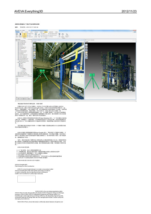
“精益建造”将加快项目整体进度,并减少损耗巴黎2012年10月11日电 /美通社/ -- AVEVA 今天在巴黎 AVEVA 世界峰会 (AVEVA World Summit) 上推出 AVEVA Everything3D (E3D)。
AVEVA E3D 将各种技术整合在一起,提出了一项新的愿景,让客户能够在工程、设计和建造等行业使用“精益”工作实践。
这将有助于加快项目的整体进度,并减少损耗。
作为 AVEVA 一体化工程与设计方案的一部分,AVEVA E3D 将多个重要创新成果融为一体,大大增强了新建工厂设计和全生命周期改造项目。
该产品最重要的一点就是将激光扫描数据和三维几何学、强大的绘图工具以及直观的用户界面整合在一起,满足一般常见设计任务的需求。
AVEVA 工程设计系统首席技术官兼主管 Dave Wheeldon 表示:“工厂设计解决方案市场日新月异,需要提出一个新的理念。
仅仅取得零误差设计已经远远不够。
经济实惠型新技术的出现已经让工厂设计的触角切实可行地延伸至供货商、制造商和施工团队等其它利益相关者。
”“采用‘精益’理念实现成本节约的一个关键在于随着工程进展远离设计办公室的团队沟通状态和建造信息的能力。
”AVEVA 战略与营销高级副总裁 Bruce Douglas 表示:“我们的客户正面临许多挑战。
力求获得更多能源和矿产资源的压力将使得工程项目面临更多、更大的技术难题。
发达市场工程师人口的老龄化与新兴市场经验的严重匮乏都要求工厂设计软件更易于使用、便于快速培训、能够缩短投产时间。
”“此外,商业市场出现了消费市场上的移动和云计算也使得异地工作人员,特别是那些在施工现场的人员能够通过状态更新和激光扫描数据将重要的完工资料反馈给设计团队。
这有助于迅速且具有成本效益地采取纠正措施,最大程度地保证施工质量,同时确保工程项目进度。
”AVEVA E3D 将包括:工厂设计系统,包含工程和原理图等专业三维建模功能,通过结合最优质的三维图形和激光扫描点云展现“真实世界”完全自动化的二维绘图能力,并与三维模型全面集成设计过程中与其它设计系统完全协同工作采用的架构支持项目重用与模块化设计,另外还支持与云/移动基础设施的集成支持与时下行业领先的系统 AVEVA PDMS 同时操作AVEVA E3D 将于2012年12月中旬面市。
Aveva 解决方案

- PDMS Cats & Specs (full intelligence transfered)
© Copyright 2010 AVEVA Solutions Limited
Interoperability Case Study (1)
- 12,114 process lines
Statoil Snøhvit
Interoperability Case Study (1)
- ..
Engineering Project Business Purpose Business Benefit Production Deployment Scope & Scale of Interoperability Technology Implemented Data Standard
Woodside Energy
Offshore Oil& Gas platforms, Australia Fast central access to latest engineering design data; manage inconsistent info from many sources Successful integration of 3rd party applications; data in neutral format gives flexibility 2005 - today: full production plant lifecycle: operations & maintenance 250,000 tags data from over 6 vendors 70 seats of AVEVA NET range of AVEVA NET Gateways ISO 15926 Reference Data Library (2005)
埃尔维斯1数字地表面模型产品说明书
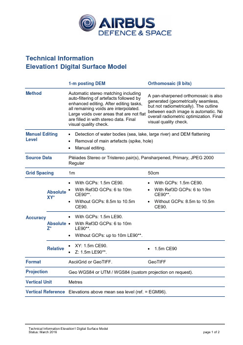
Technical InformationElevation1 Digital Surface Model1-m posting DEM Orthomosaic (8 bits) Method Automatic stereo matching including auto-filtering of artefacts followed by enhanced editing. After editing tasks, all remaining voids are interpolated. Large voids over areas that are not flat are filled in with stereo data. Final visual quality check.A pan-sharpened orthomosaic is also generated (geometrically seamless, but not radiometrically). The cutline between each image is automatic. No overall radiometric optimization. Final visual quality check. Manual Editing Level• Detection of water bodies (sea, lake, large river) and DEM flattening • Removal of main artefacts (spike, hole)• Manual editing. Source DataPléiades Stereo or Tristereo pair(s), Pansharpened, Primary, JPEG 2000 Regular Grid Spacing 1m 50cm AccuracyAbsoluteXY* • With GCPs: 1.5m CE90. • With Ref3D GCPs: 6 to 10m CE90**.• Without GCPs: 8.5m to 10.5m CE90.• With GCPs: 1.5m CE90.• With Ref3D GCPs: 6 to 10m CE90**. • Without GCPs: 8.5m to 10.5m CE90. Absolute Z* • With GCPs: 1.5m LE90. • With Ref3D GCPs: 6 to 10mLE90**.• Without GCPs: up to 10m LE90**.Relative• XY: 1.5m CE90. • Z: 1.5m LE90**. • 1.5m CE90 FormatAsciiGrid or GeoTIFF. GeoTIFF Projection Geo WGS84 or UTM / WGS84 (custom projection on request). Vertical Unit MetresVertical Reference Elevations above mean sea level (ref. = EGM96).Accuracy Level The accuracy specification of Elevation1 (with GCPs) is similar to the HRE10 NGA classification*.GCPs •Ground control points can help to attain optimal accuracy.•The customer can provide accurate GCPs (~10cm XYZ) that are visible in the stereopair.AOI •Large AOIs can be covered by adjacent stereopairs; the DEM mosaic willbe seamless with no edge effect.• A minimum width of 10km is required.•Minimum area = 100 sq.km. / Maximum area = 2,000 sq.km. (larger areas will be considered on a case-by-case basis).No Data Value •The value –32767 is set for areas where the elevation is not determined(around AOI).•Potential clouds (if any) are considered as ‘No Data’.Metadata No additional metadata is provided with the DEM.Tiling DEM 1m tile is 10km x 10km (~600 Mb).B/H Ratio •The optimal B/H ratio is in the range of [0.3 – 0.6].• A high ratio (i.e. 0.6) is suitable for flat areas.• A low ratio (i.e. 0.3) is suitable for steep terrain.Availability Product limited to mineral or open areas with little (or low) vegetation and few buildings. Urban areas are only proposed on request with a custom price.Perfect for micro-relief in arid areas.。
VAT Vakuumventile AG 蒸汽阀门说明书

Control Gate Valvewith 3-position pneumatic actuatorSample pictureThis manual is valid for the valve ordering number(s):640.. - .E.8 - . . . .The fabrication number is indicated on each product as per the label below (or similar):Explanation of symbols:Read declaration carefully before you start any other action!Keep body parts and objects away from the valve opening!Attention!Hot surfaces; do not touch!Product is in conformity with EC guidelines, if applicable!Loaded springs and/or air cushions are potential hazards!Disconnect electrical power and compressed air lines. Do not touch parts under voltage!Wear gloves!Imprint:Manufacturer VAT Vakuumventile AG, CH-9469 Haag, SwitzerlandWebsite Phone+41 81 771 61 61Fax+41 81 771 48 30Email***************Publisher VAT Vakuumventile AG, CH-9469 Haag, SwitzerlandEditor VAT Vakuumventile AG, CH-9469 Haag, SwitzerlandPrint VAT Vakuumventile AG, CH-9469 Haag, SwitzerlandCopyright © VAT Vakuumventile AG 2008No part of these Instructions may be reproduced in any way (photocopies, microfilms or anyother reproduction processes) nor may it be manipulated with electronic systems, duplicated ordistributed without written permission from VAT. Offenders are liable to pay damages.The original VAT firmware and updated state of the art versions of the VAT firmware areintended for use with VAT products. The VAT firmware contains a limited, time unlimited userlicense. The VAT firmware may not be used for purposes other than those intended nor is itpermitted to make copies of the VAT firmware. In particular, it is strictly forbidden to give copiesof the VAT firmware to other people.The use of trade names, brand names, trademarks, etc. in these Instructions does not entitlethird parties to consider these names to be unprotected and to use them freely. This is inaccordance with the meaning of the laws and acts covering brand names and trademarks.Contents:1Use of product (4)1.1Technical data (4)2Installation (5)2.1Installation into the system (5)2.2Connections (5)2.2.1Tightening torque for mounting screws on flanges (5)2.2.2Admissible forces (6)2.2.3Compressed air connection (7)2.2.4Actuator position (example) (8)2.2.5Compressed air connection by external solenoid (option) (8)2.2.6Electrical connection (9)3Operation (11)3.1Normal operation (11)3.1.1Adjustment of the intermediate position (11)3.2Operation under increased temperature (12)3.3Behavior in case of differential pressure (12)3.4Behavior in case of compressed air failure (12)3.5Behavior in case of power failure (12)4Trouble shooting (13)5Maintenance & repairs (13)5.1Preventive maintenance (14)5.1.1Procedures (15)6Drawing (17)7Spare parts (18)8Warranty (19)1 Use of productUse product for clean and dry indoor vacuum applications under the conditions indicated in chapter «Technical data» only! Other applications are only allowed with the written permission of VAT.Corrosive process gases may impact the performance of the product. Please contact VAT to assure that the product is compatible with the process gases used in your application.1.1 Technical dataPressure range DN 63 - 200: 1 x 10⁻⁸ mbar to 2 bar (abs)DN 250 - 400: to 1 bar (abs)Differential pressure on the closed gate DN 63 - 200: 2 bar in either directionDN 250 - 400: 1 bar in either directionMax. differential pressure at opening 30 mbarAdmissible temperature: Valve < 150°CActuator < 50°CCycles until first service 200000Supply voltage see label on solenoid control valvePower required 2 x 2,5 WContact rating of position indicator 5 A / 250 V AC, 3 A / 50 V DCCompressed air pressure 4 - 7 bar / 56 -98 psiFurther data according to VAT catalogue «Vacuum Valves 2008».2 Installation2.1 Installation into the systemThe valve seat side is indicated by the symbol: on the connection flange.2.2 Connections2.2.1 Tightening torque for mounting screws on flanges1. Mounting with centering ringTighten mounting screws of the flanges uniformly in crosswise order. Observe the maximum torque levels in the following table. Higher tightening torques deform the valve body and can lead to an improper function of the valve.2. Mounting with O-ring in groove2.2.2 Admissible forcesForces from evacuating the system, from the weight of other components, and from baking can lead to deformation of the valve body and to malfunction of the valve. The stress has to be relieved by suitable means, e.g. bellows sections. The following forces are admissible:lbf ft2.2.3 Compressed air connectionConnect air pressure to inputs '1' of the solenoids (internal thread R 1/8“, 1/8“ NPT for USA)Solenoid valve:Solenoid valve for impulse actuation:Make sure the emergency operation screws are in remote position (fully counter-clockwise)Note: Compressed air pressure (above atm): 4 - 7 bar / 56 -98 psiAttention:For proper function of the valve it is essential to use equal air pressure at OPEN -, CLOSE - and MIDDLE Pos. inlets. See table on page 6. Please consider that different solenoids, tube lengths and diameters can affect the air pressure.Compressed air may only be connected if- valve has been installed into the vacuum system - moving parts cannot be touched Use only clean, dry or slightly oiled air!For secure switching of solenoids, the inner diameter of the air connection tubes has to be: - 4 mm for lengths up to 1 m- 6 mm for lengths from 1 m to 5 m - 8 - 10 mm for lengths above 5 m2431524315schematic: schematic:2.2.4 Actuator position (example)Position A (Standard) Position B (Option)Note: For actuator position of your valve refer to the dimension diagram of your valve.2.2.5 Compressed air connection by external solenoid (option)Required solenoids: - Two 5/2 way valvesAir connections : - Adapter with internal thread R 1/8“ (1/8“ NPT for USA) mounted to the pipe thread screws 'A' and 'B' instead of the solenoids. The pipe thread screws have also the function of an orifice for air pressurereduction. They must not be removed or replaced.- L-type connection 'C' with internal thread R 1/8“ and integrated orifice fo r air pressure reduction (DN63 - 200: 1.4 mm, DN 250 - 400: 1.8mm)Apply compressed air pressure according the following table:2.2.6 Electrical connectionVerify that mains voltage matches voltage stated on the solenoid! Sockets for position indicator and solenoid are supplied with the valve.Do not touch electrical parts under voltage!Electrical power may only be connected if:valve has been installed into the vacuum systemmoving parts cannot be touchedWire solenoid and position indicator according to the following diagrams.V1 = impulse solenoid for main cylinder(next to pneumatics)V2 = impuse solenoid for auxiliary cylinderMV1 = solenoid coil for openingMV2 = solenoid coil for closingTo open energize the solenoids MV1 of V1 and V2 simultaneouslyTo close energize the solenoids MV2 of V1 and V2 simultaneouslyTo throttle energize the solenoids MV1 of V1and MV2 of V2 simultaneously3Operation3.1 Normal operationOperation is allowed only after proper installing procedure.3.1.1 Adjustment of the intermediate positionThe intermediate position can be adjusted (allen wrench 8mm) independently of the air pressure by means of the bolt screw 'M' (see also page 7 and picture below), on the face side of the auxiliary cylinder.Before moving the bolt screw 'M', open the locking screw (B) (allen wrench 2.5mm). After adjustment the intermediate position, fasten the locking screw (B).For easy adjustment, VAT is recommending to switching off the compressed air during adjustment of the intermediate position.A-side actuator: turning bolt screw 'M' clockwise moves the intermediate position to open B-side actuator: turning bolt screw 'M' clockwise moves the intermediate position to closeThe position indicator on the valve can be adjusted for the set intermediate position. Move valve with bolt screw 'M' to the desired position and than turn the screw (A) with a screwdriver size 2 on top of the position indicator box in either direction until the microswitch Lz switches. (Lz = position indicator for intermediate position)Aposition indicator for intermediate position3.2 Operation under increased temperatureSee «1.1 Technical data»3.3 Behavior in case of differential pressureNote: Do not open the valve, if the differential pressure on the gate is larger than 30 mbar.3.4 Behavior in case of compressed air failureValve closed: valve stays closed and leaktightValve open or Intermediate position: valve stays open or moves into closed (not leaktight) position, depending on the mounting position3.5 Behavior in case of power failureStandard solenoids: valve closesImpulse solenoids: valve moves to the position of last command and stays in this position4 Trouble shootingCompressed air?Electrical connection? Differential pressure Mechanical parts blocked? Check compressed air at solenoidsIs differential pressure < 30 mbar?Do not operate valve, while differential pressure is > 30 mbar. Equalize pressure first.Is valve cable connected properly?Mechanical parts blocked? (cleaning)Sealing surface gate GateO-ring Clean valve seat and gate!Check surface of seat and O-ringChange O-ring, if necessaryFlange seals leaktight?Bonnet seal leaktight?Screws at bonnet tightened properly?If you need any further information, please contact one of our service centers. You can find the addresses on our website: http://www.vat.ch5 Maintenance & repairsUnder clean operating conditions, the valve does not require any maintenance during the specified cycle life. Contamination from the process may influence the function and requires more frequent maintenance.Before carrying out any maintenance or repairs, please contact VAT. It has to be individually decided whether the maintenance/repair can be performed by the customer or has to be carried out by VAT. The fabrication number on the valvehas always to be specified.All supplies (e. g. compressed air, electrical power) must be disconnected for removal/installation of the valve from/into the system and for maintenance work.Even with disconnected supply, loaded springs and/or air cushions in cylinders can be potential hazards. Keep fingers and objects away from the valve opening!Products returned to VAT must be free of harmful substances such as e.g. toxical, caustic or microbiological ones. If products are radioactively contaminated, fill in the VAT form «Contamination and Radiation Report» and send it with the product. The form is available at VAT. The maximum values indicated in the form must not be exceeded.5.1 Preventive maintenanceThe numbers in brackets refer to the drawing on page 17.Note!The process environment of your application (i.e. corrosive gases, deposition on parts inside valve body) may suggest shorter preventive maintenance intervals than suggested below.Baking of the valve is highly recommended for contaminating processes. VAT offers customized heater box forseries 64 valves.For quick maintenance, VAT recommends to exchange the complete gate assembly in order to reduce thedowntime of the system.Warning! DN 160 – 400: Never remove the striking plate (22) of the ball guidance (18)!Recommended maintenance after every 100'000 cycles (after 50'000 cycles for DN 400)Clean gate O-ring (or to replace it, if necessary), clean the inside surfacesInspect the bonnet seal and inspect ball bearings and crank boltReplace all parts witch are per process caused corrosion or material pollution (recommended spare parts kit 'C')Recommended maintenance after every 200'000 cycles (after 100'000 cycles for DN 400)Additional to the 100'000 cycles maintenance interval, VAT recommends to clean and lubricate the ball bearings (replace it, if necessary), replace the locking balls, replace the crank bolt, inspect, clean and re-lubricate the ball guide plate (replace it if the balls have seized in the bushings), inspect, clean and re-lubricate the feedthrough O-ring (replace it if necessary) The following table refers to the procedures in the following chapter and the spare parts list on page 17.*) Definition of a cycle: Movement of the gate from open into closed or control position and back into open position5.1.1 Procedures1.Precondition for all maintenance workVent both valve chambersOpen gate valveShut off air supply and electrical power Disconnect all cables to the actuator2.Removal of the gate assembly (4) / Replacement of the crank bolt (6) / Replacement of the bonnet seal (3)Unfasten the bonnet screws (1)Remove the bonnet plate (2) and the bonnet seal (3)Pull the lever (17) a little bit out of the bonnet openingLoosen the hexagonal socket-head bolt (7) for the crank bolt (6)Remove the crank bolt (6), while lifting the gate assembly (4) a little bit if necessarySlide out the gate assembly (4) carefully from the body and put it on a clean workshop placeRe-assemble in reverse directionFasten the screws (1) crosswise with equal torque: 14 Nm (10 lbf ft) with DN 63 - 100 18 Nm (13 lbf ft) with DN 160 - 4003.Replacement of the gate O-ring (5)Put a suitable tool beneath the O-ring at the venting hole and lift the O-ring carefully out of the groove (take carethat the groove will not be damaged)Clean groove and sealing surfaceInstall new O-ring by pressing it crosswise uniformly into the groove. Make sure, the O-ring is not twisted (payattention to the seam of the O-ring)4.Replacement of the ball bearings (24)DN 63, DN 160 - 200: Replace the complete ball bearing assembly (DN 63: 1 pc, DN 160 - 200: 2 pcs) DN 100, DN 250 - 400: Replace each single ball bearing and pull out the its centre ring (4 pcs)5.Replacement of the locking balls (21)Put the gate assembly (4) carefully on a clean workshop place with the O-ring side to the bottomDN 63: Push center spring down and dismount two-piece circlip from the center bearing. Lift off ball guide plateDN 100 - 400: Unscrew the hexagonal nuts (19). Lift off counter plate (20) and ball guide plate (18) Remove the locking balls (21)6.Replacement of actuatorClose and lock valveRemove the position indicator box (8) from the actuator and unscrew the 2 hexagon bolts of the actuatorPull off actuator from the gear wheel of the feedthrough assembly (9). Take hold of the actuator on both sides ofthe actuator flange and use your thumb to push against the shaft of the feedthroughMake sure that rack of the actuator is in closed positionCheck whether valve is closed and properly lockedSet up actuator on gear wheel and shaft in a right angle to the valve. If the actuator cannot engage with the gearwheel, turn actuator under little pressure a few degrees counter-clockwise until it engages with the gear wheel For change into position A2 or B2, first unscrew the 2 hexagonal bolts of the feedthrough assembly and put theminto the bolt holes in the lateral axisTurn the actuator slightly back to the right angle position so that the 2 bolts can fit loosely in the threaded holesFasten the 2 bolts only when flange area of the actuator lies tightly on the actuator flange of the valveSet position indicator box (8) on actuatorAlign position indicator so that the 4 cylinder head screws will fit loosely in the threaded holes. Fasten screwsVerify the correct adjustment of the position indicator. In the position where the microswitch has switched, the valvemust be closed and locked7.Replacement of feedthrough O-ring (11)Remove gate assembly (4) as per items 1 and 2Remove actuator as per item 6Push the roll pin (12) out of the feedthrough shaft. Use VAT feedthrough assembling tool or a punch. Remove lever(17).Loosen the 2 screws of the feedthrough assembly (9)Slide out complete feedthrough assembly (9), carefully dismantle feed through assembly and remove thefeedthrough O-ring (11)6 Drawing7 Spare partsPlease specify the fabrication number of the valve (see yellow label on valve) when ordering spare parts. This is to ensure that the appropriate spare parts are supplied.8 WarrantyEach product sold by VAT Vakuumventile AG (VAT) is warranted to be free from the manufacturing defects that adversely affect the normal functioning thereof during the warranty period stated in VAT's «Terms of Sale» immediately following delivery thereof by VAT, provided that the same is properly operated under conditions of normal use and that regular, periodic maintenance and service is performed or replacements made, in accordance with the instructions provided by VAT. The foregoing warranty shall not apply to any product or component that has been repaired or altered by anyone other than an authorized VAT representative or that has been subject to improper installation or abuse, misuse, negligence or accident. VAT shall not be liable for any damage, loss, or expense, whether consequential, special, incidental, direct or otherwise, caused by, arising out of or connected with the manufacture, delivery (including any delay in or failure to deliver), packaging, storage or use of any product sold or delivered by VAT shall fail to conform to the foregoing warranty or to the description thereof contained herein, the purchaser thereof, as its exclusive remedy, shall upon prompt notice to VAT of any such defect or failure and upon the return of the product, part or component in question to VAT at its factory, with transportation charges prepaid, and upon VAT's inspection confirming the existence of any defect inconsistent with said warranty or any such failure, be entitled to have such defect or failure cured at VAT's factory and at no charge therefor, by replacement or repair of said product, as VAT may elect. VAT MAKES NO WARRANTY OR REPRESENTATION OF ANY KIND, EXPRESS OR IMPLIED, (INCLUDING NO WARRANTY OR MERCHANTABILITY), EXCEPT FOR THE FORE-GOING WARRANTY AND THE WARRANTY THAT EACH PRODUCT SHALL CONFORM TO THE DESCRIPTION THEREOF CONTAINED HEREIN, and no warranty shall be implied by law.Furthermore, the «Terms of sale» at the back of the price list are applicable.。
EN1811

EN1811:2023欧盟镍释放量检测标准更新解读张烨雯 罗 晶 王佳琦(上海海关机电产品检测技术中心)摘 要:EN1811作为欧洲检测仿真饰品及其他接触皮肤的产品中镍释放量的主要标准之一,是欧盟对此类产品重要的技术壁垒。
2021-2022年我国出口欧盟的仿真饰品中,有相当一部分由于不符合该标准而被拦在欧盟市场之外。
2023年2月欧洲标准化委员会(CEN)发布了新版标准EN1811:2023,取代EN1811:2011+A1:2015。
本文主要介绍了EN1811:2023相对于旧版标准的主要变更内容,为中国仿真饰品等产品出口企业提供技术指导,使其充分了解新版标准的变化,确保出口产品符合欧洲新版标准的技术要求。
关键词:仿真饰品,EN1811,镍释放量,新旧标准差异DOI编码:10.3969/j.issn.1674-5698.2023.12.016Interpretation of the New Version of EN 1811 for the Detection of Nickel ReleaseZHANG Ye-wen LUO Jing WANG Jia-qi(Technical Center for Mechanical and Electrical Product Inspection and Testing of Shanghai Customs District)Abstract: EN1811, as one of the main European standards for the detection of nickel release in imitation jewelry and other products intended to come into direct and prolonged contact with the skin, is an important technical barrier for such products in the EU. In 2021-2022, a considerable part of the simulation jewelry products exported to the EU are blocked outside the EU market because they do not meet the standard. The European Committee for Standardization (CEN) issued a new version of EN 1811 in February 2023, replacing EN 1811:2011+A1:2015. This paper mainly introduces the main changes of EN 1811:2023 compared with the old version, to provide technical guidance for Chinese export enterprises of imitation jewelry and other products, so that they can fully understand the changes of the new standard, to ensure their export products meet the new standard.Keywords: imitation jewelry, EN1811, nickel release, difference between old and new versions镍是人体必需元素,也是致敏元素,长期接触人体皮肤可能导致过敏并引发皮肤炎症,严重的可能致癌[1-5]。
威特仕焊护用品 - 烧焊手套说明书

数值位置抗阻测试第一位燃烧性能第二位接触导热第三位热气流第四位折射热能警告: 威特仕焊护用品已通过德国TUV测试并获得证书.要想了解其他更多的信息,如 EN 标准, 测试方式, 测试报告, 产品证书和其他产品, 请发电子邮件至:*****************或登陆我们的网站: EN407, 2004: 抗热风险的劳保手套数值位置抗阻测试第五位细金属熔渣第六位大金属熔渣EN388, 2003: 抗机械性风险的劳保手套3121413X4X类型A 类型 B要求EN系数最低测试值抗导电绝缘pr1149-2 电阻≥106Ω电阻≥105Ω抗磨损 EN388 2 500 周期 1 100 周期抗刀割EN388 1 指数1.2 1 指数1.2抗撕破EN388 2 25 牛顿 1 10 牛顿抗刺破 EN388 2 60 牛顿 1 20 牛顿抗燃烧EN407 3 2抗导热EN407 1 100℃ 1 100 ℃抗热气流EN407 2 HTI≥7 0抗细金属熔渣EN407 3 25 粒 2 15 粒灵敏度(拿取针子的直径) EN420 1 ≤11mm 4 ≤6,5mm最低测试值手掌尺寸7½ 8½ 9 9½ 10½威特仕尺寸标签S M L XL XXL手套总长度( mm) 310 320 330 340 350测量尺寸(mm) 190 216 229 241 267数值位置 抗力测试级别 1 级别 2 级别 3 级别 4第一位磨损 (周期) 100 500 2000 8000第二位刀割 (指数) 1,2 2,5 5,0 10,0第三位撕破(牛顿) 10 25 50 75第四位刺破(牛顿) 20 60 100 150级别5—20,0——手套类型: 烧焊手套商标: 尺寸:参照手套上的印唛健康因素:产品物料的铬(VI)含量,PH值,五氯苯酚(PCP)含量都经过测试达安全健康标准.颜色: 颜色是经过天然物料处理.以下是对印在手套上的图案的说明:使用说明:该手套被用于敏感度要求较高的焊接,比如说TIC焊接.保证:该产品保证制造缺点,因应用范围的不同,选择正确的产品是使用者的责任.洗涤,烘干和烫平:应该使用标准的没有漂白和酸性的洗涤剂,经过一两次洗涤后,皮的特性会改变, 洗涤后的皮淬水是典型的.机器烘干和烫平是可行的,但是不建议这样做.原料运用:该手套的手掌运用绒面猪青皮,猪二层皮袖,并用KEVLAR® 3线缝制.尺码如果产品上的数值是 “X “ , 那么数值位置是没有经过测试的UV:这个标准没有测试方法针对UV放射,但是一般使用这些材料都没有问题.导电危险性:这些产品能传递电流, 当产品潮湿时比较危险.威特仕产品: 10-1003手套上的CE印唛指出其本身已根据89/686/EEC指引标准2进行测试和认证.手册EN12477, 09.2005 类型 A/B威特仕欧洲分公司:Weldas Europe B.V.Blankenweg 18 NL-4612 RC Bergen op Zoom HollandE-mail:*****************威特仕全球总公司,即威特仕美国公司:Weldas Company128 Seabord Lane Franklin TN 37067 USAE-mail:***************该产品的制造商是: 威特仕威特仕地址:杜邦™ 和KEVLAR®是E.I.杜邦公司的注册商标, Softouch 是威特仕公司的注册商标.EN12477, 2005: 焊工劳保手套 (最低测试值要求)尺码与 EN 12477, 2005 / EN 420, 2003一致贮存: 在5摄氏度下干燥贮存,不要在一个卡板上堆叠5箱以上.。
维沙伊技术(Vishay Intertechnology)光学传感器产品说明书

R e fl e c ti v eS e ns o r sW i t hA n a l o gO u tp u tT r i p l e an dQ u ad C ha n ne lT r a n s mi s s iv e Se n so r sA m b i e nt L i gh t Se n so r sW i t hA n a l o ga n dD i gi t a lO u tp u tI n t e g r at e dP r ox i mi t y an db i en t Li g h tS e ns o r sW i t hu t pu tS e ns o r sW i t hA n al o gO u tp u tI n t eg r at e dM ul t i pl e Ba n dS e ns o r sS i ng l ea n dD u alC h an n el T ra n sm i ss i v eS e ns o r sH i gh Re s ol u t io n Se n so r sf o rU V Aa n dU V BM e as u r em e nt sU VS E NS O RST C XT13X0X01C O LO RS E NS O RST R AN S MI S S IV ES E NS O RSV C NL F AM I LYA M BI E NT L IG H TS E NS O RST C UT1630X01T C UT1800X01R E FL E CT I V ES E NS O RSNotes: (1) All optical sensors have phototransistor output except where noted (2) Relative collector current > 20 % (3) TCND5000 has a PIN photodiode outputNotes: (1) All optical sensors have phototransistor output (2) Dual channel (3) Triple channel (4) Quad channel (5) Products ending in “X01” are AEC-Q101 qualified(1)1206, SMD 5 mm, flat top5 mm 3 mmNotes: (1) E v = 100 lux, V CE = 5 V , CIE illuminant A, typical (2)Products ending in “X01” are AEC-Q101 qualifiedPackageNotes:(1)Products ending in “X01” are AEC-Q101 qualifiedNo matter what car you drive,optical sensors are close by.Think automotive, think Vishay! Vishay’s proximity, reflective,transmissive, and ambient lightsensors put the “smart” intosmart devices with best-in-class performanceUseful Links • Optical Sensors gateway/optical-sensors/• Transmissive Sensors infograph/doc?48352• Proximity Sensors infograph/doc?49820• Current Estimator calculator/optoelectronics/opto-sensors-calculator/• Vishay Automotive Grade Optoelectronics selector guide /doc?49071• Sensor starter kit/moreinfo/SensorXplorer/。
- 1、下载文档前请自行甄别文档内容的完整性,平台不提供额外的编辑、内容补充、找答案等附加服务。
- 2、"仅部分预览"的文档,不可在线预览部分如存在完整性等问题,可反馈申请退款(可完整预览的文档不适用该条件!)。
- 3、如文档侵犯您的权益,请联系客服反馈,我们会尽快为您处理(人工客服工作时间:9:00-18:30)。
CHAPTER 1 1IntroductionAVEVA Everything3D™(AVEVA E3D™) enables designers to create a 3D model of a Plant design in a multi-discipline environment. One of these disciplines is Equipment modelling and AVEVA E3D enables designers to create 3D representations of plant equipment of all types for use within the wider context of the model.The aim of this training module is to provide basic knowledge of Equipment Modelling within AVEVA E3D.At the end of this course the Trainee will be able to:∙Explain the basics of Equipment Modelling in AVEVA E3D.∙Create equipment using primitives.∙Demonstrate the use of Standard Equipment models.∙Explain the creation of Electrical Equipment.∙Prepare equipment reports.∙Utilise Equipment Associations.∙Understand Hole Management for Equipment.Explain how to create Volume Models in AVEVA E3D.∙course.methods, and complete the set exercises.Menu pull downs and button press actions are indicated by bold dark turquoise text.Information the User has to Key-in will be bold red text.Additional information notes and references to other documentation will be indicated in the styles below.Additional informationRefer to other documentationSystem prompts will be bold and italic in inverted commas i.e. 'Choose function'.Example files or inputs will be in the courier new font. If users are required to enter information as part of an example, appropriate fonts and styles previously outlined will be used.Login to AVEVA E3D using the details provided by the Trainer. They will typically be as shown below:Project: TRA (Training) Username: A.EQUIPMAN Password: AMDB: A-EQUIPMENT Module: ModelOn the TOOLS tab, in the Training group, click the Setup button to display the Training Setup form. Navigate to the Equipment tab .click the Apply button and close the form.This page is intentionally left blank2 Overview of Equipment ModellingThis chapter provides an overview of general features for Equipment Modelling in AVEVA E3D.Equipment (EQUI) elements may represent any type of equipment in a Plant. It is important is that the modelled equipment is a reasonable representation of the actual equipment. Specifically, that it is volumetrically and spatially correct and that any nozzles, are correctly positioned, orientated and specified.The level of detail of the equipment model depends on the project requirements. While adding greater detail provides a more realistic representation, it also takes more time and as such will cost more. Different modelling methods are available to designers. Which method is appropriate often relates to the degree of information available, the significance of the modelled item, and the frequency with which theitem will be created in the model.Equipment (EQUI ) elements are owned by Zones (ZONE ).EQUI elements may own one or more optional Sub-equipment (SUBE ) elements. The SUBE elements are used to break down equipment into sub-parts, e.g. main equipment and supports.Both the EQUI and the SUBE elements can own Primitives .Primitives are the elements that are displayed in the 3D View to represent theequipment and act as the building blocks for equipment modelling within AVEVA E3D.Equipment may be modelled in three ways using AVEVA E3D.∙ Basic principles using primitives – this method is generally used for one-off equipment items orwhere the size of the equipment doesn’t change. Repeat copies of equipment c an be used in the model by using the Standard Model Library .Refer to TM-1802 AVEVA Everything3D™ (2.1) Model Utilities for information on Standard ModelLibrary. ∙Design templates – this method uses primitives and other elements in a design template. Thetemplates are generally parametrised such that the equipment may be re-sized for each instance of the template in the design.Creating Equipment Design Templates is outside the scope of this training guide. Refer to TM-1852AVEVA Everything3D ™ Equipment Design Templates (2.1), however, creating equipment elements using design templates is described.∙Importing models – equipment models may be imported using the Mechanical Equipment Interface or from different file formats.Using each of these methods is described fully later in the training guide.3Equipment Modelling Using PrimitivesThis chapter explores a number of issues that designers should consider prior to commencing any equipment modelling and describes how equipment elements can be created with basic modelling methods using primitives.Conventionally, equipment items are named using the tag number, e.g. /E1101, /P1001-A, /D2016, etc. However, any name or naming convention may be used. It is not usual to name primitives, except nozzles, unless they need to be identified for some purpose.Nozzles are named and generally prefixed by the equipment name to make them unique, e.g. /E1101-N1, /P1001-A/N1, /D2016/1. Naming the nozzles also helps in identification when connecting pipework to them. Nozzle names will also be referenced on Piping Isometrics.Whatever names are given, the naming convention is usually defined by the project specification. It is possible that the project may have Autonaming rules set up for items such as nozzles so that the project conventions are followed in every detail.The position of the equipment origin is a key consideration prior to commencing modelling. The point selected for an equipment origin is often dictated by other project information, such as known co-ordinates or adjoining structures and pipe elements. Understanding the position of the origin of equipment, sub-equipment and primitive elements will help designers model more effectively.Equipment elements, Sub-equipment elements and Primitive elements each have an origin. The origin position is held within each elements Position attribute.The EQUI element’s Position attribute holds the equipment origin position. By default, the position is expressed in world co-ordinates, however the user can change this to other design elements if required. If SUBE elements are used, the Position attribute defines the SUBE origin position with respect to the equipment origin (default).A solid primitive’s Position attribute defines the position of the primitive’s origin with respect to its owner, i.e. the EQUI origin or the SUBE origin.For all negative primitives, the Position attributes define the position of the negative primitive’s origin with respect to its owning solid primitive’s origin.The following primitives are available for equipment modelling in AVEVA E3D.Box (BOX)Cylinder (CYLI)Cone (CONE)Snout (SNOU)Pyramid (PYRA)Circular Torus (CTOR)Rectangular Torus (RTOR) Dish (DISH)Sloped Cylinder (SLCY)Extrusion (EXTR)Solid of Revolution (REVO)Nozzle (NOZZ)Equipment elements consist of a collection of AVEVA E3D primitives, arranged in 3D space to represent the real object.When a new piece of equipment is to be built, one of the first decisions to be made is which primitives are going to be used to create the representation required.General ly the ‘internals’ of any equipment are not modelled as it only the external representation that is required.In this simple example of a horizontal vessel, seven primitives are positioned and orientated such that they represent a vessel. There is no ‘connectivity’ between the primitives.Each primitive has a set of P-points at fixed locations. A P-point is a point that has a position and direction attribute as well as other attributes that are used by other modules and applications.P-points are numbered, with P0always being at the origin of the primitive. For example, a BOX has 7 P-points:∙P0 is in the middle of the box.∙P1 is in the centre of the top face of the box and points away from the face in a +ve Z direction.∙P2, P3, P4 and P5 are located on the four vertical faces. Each located at the centre of and pointing away from its face.∙P6is located in the centre of the bottom face of the box pointing away from the face in a -ve Z direction.For equipment modelling, P-points are used for locating and aligning primitives.Appendix A contains a list of primitives showing selected attributes and P-points.To obtain a desired shape or effect in the model, negative primitives may be used to ‘cut’ a solid primitive.Negative primitives are owned by solidprimitives and will only negate their owner.The negation is controlled using the HolesDrawn checkbox on the Representation tabof the Graphics Settings form.All solid primitives, except Nozzles, have anequivalent negative primitive whose attributesare the same but the names are different, asshown in the table.This worked example builds a piece of process equipment, a Reboiler, tagged E1301, from the AVEVA Plant training project.The equipment locations for the project are shown on the following Equipment Location drawing below.The dimensions for Reboiler E1301 are shown on the Equipment Arrangement drawing below.Before starting to model E1301, or any equipment item, key decisions need to be made:1. The location of the equipment origin.The equipment origin can be placed anywhere. It could be placed on the bottom of one of the saddles so that it may be located on a foundation, however, looking at the location information on the Equipment Location drawing, it would be easier to place the origin on the centreline of the equipment in line with nozzles NS1 and NS2.This would give an equipment origin position of W 319150 N 296950 U 101470.2. The orientation of the equipment.There is little point in modelling the equipment in one orientation and then re-orientating it when complete. From the Equipment Location end to the North, so this is the orientation that will be used for the primitives. The equipment will use the default orientation of Y is N and Z is Up.3. The primitives to be used.Looking at the Equipment Arrangement drawing for E1301 it may be broken down to the following primitives:∙ 6 x Cylinders∙ 2 x Boxes∙ 5 x Nozzles∙ 1 x DishTotal 14 PrimitivesClear the Drawlist, if required.Make ZONE-EQUIPMENT-AREA01the CE and on the EQUIPMENT tab, in the Create group, click the Equipment button to display the Equipment Creation form.In the Naming text box enter E1301.Change the East/West options list to West and enter 319150 into the textbox,Enter 296950 in the North textbox and 101470 in the Up textbox.Enter Reboiler in the Description textbox. All other attribute fields can be left unset at this point.Click theOK button to create the equipment element with the specified name and at the specified co-ordinates.At this time nothing is displayed in the 3D View as the equipment does not own any primitives.Right click on the newly created element in Model Explorer and select Attributes… from the pop-up menu to display the Attributes form.Check the Position attribute.The Orientation is the default orientation, i.e. Y is N and Z is Up (X is East), as the Equipment Creation form does not allow an orientation to be specified.As this is the required orientation, the equipment does not need to be re-orientated.Close the Attributes form.3.4.3 Creating the PrimitivesAlthough it is not important in which order the primitives are built, it makes sense to model the main ‘body’ of the Reboiler first, i.e. the longest cylinder(Cylinder 1). From this base most of the other primitives can be positioned.Before beginning to model the primitives for this equipment, it is important to consider your working plane. The cylinders modelled here will have their Z-axes’as the North/South axis, thus we will use the UW plane. This may be selected from VIEW > Local Coordinate System > UW or by selecting the plane from the PowerCompass TM. We will remain in this plane for the entire worked example.In the Create group of the EQUIPMENT tab, select the Cylinderoption from the primitive gallery.This will activate the Contextual Editor, which will guide the user though the creation stages.The southern end of the cylinder is 290 – 60 = 230mm South of the equipment origin. We will use this as its base centre.Enter E 0 N -230 U 0 in to the co-ordinates boxes. After typing each co-ordinate press the Tab key to lock it and advance to the next co-ordinate. Once complete press the Return key to advance.From the Equipment Arrangemen t drawing, the length of this cylinder can be derived as 6590 – 60 –60 = 6470mm and has a diameter of 835mm.Enter 835 in the Diameter textbox, followed by the Return key.Enter -6470 in the Height textbox followed by the Return key.This will complete the cylinder creation. Right click and drag to 11 O’clock on the PowerWheel TM to set Limits Extents.The next primitive to be created is the flange on the southern end of the equipment (Cylinder 2). On the Create Primitive form click Cylinder again to display the contextual editor.From the Equipment Arrangement drawing, the thickness of the flange is 60mm and the diameter is 960mm.With equipment E1301 as the CE, type CYLI into the 3D View.Position the base centre of the new cylinder at P1 of the first cylinder. P-point snaps may be turned on by holding <Shift>, right clicking and dragging to 12 O’clock on the snaps PowerWheel TM.Enter 60 in the Height input box and 960 in the Diameterinput box.3.4.3.1 Using CopyThe next primitives to create are the second and third flanges (Cylinder 3 and 4), just North of the equipment origin and at the north end of Cylinder 1 respectively. These primitives could be created, as described previously. However, they may also be created by copying the first flange cylinder. Double click the equipment, then double click Cylinder 2. Type CO into the 3D View. When asked to specify base point of displacement, pick P1 of Cylinder 2.Then enter E 0 N 640 U 0 into the displacement co-ordinates.Then choose P2 of Cylinder 1 to copy to.Press the Return key to exit the copycommand.Cylinder 5 may be created using a similar process to Cylinder 2. Pick P2 of Cylinder 4 as the base centre, enter 910 for the diameter and -300 for the height. Dish 1 is positioned at the north end of Cylinder 5. The Create a Dish button may be found in the second row of the Primitives Gallery . Pick P2 of Cylinder 5 for the base centre. Note: A preview will not be visible since it will be obscured by Cylinder 5,due to its default orientation.Enter 910 for the diameter . When prompted for the dish height, press the down arrow and select Knuckle Radius , then input 75. Then input -200 for the height.See page 101 for more details regarding dish definition and knuckle radii.3.4.3.2 Creating NozzlesThe Nozzle Schedule on the Equipment Arrangement drawing shows that Reboiler E1301 has five nozzles named NS1, NS2, N1, N2 and N3. For this example the nozzles will be 180prefixed using the equipment name and a forward slash, e.g. E1301/NS1.A Nozzle (NOZZ ) primitive has its origin, P-point P0, at the face of the nozzle flange and is co-incident with P-point P1.P-point P2 is at the bottom of the ‘stem’ of the nozzle and the Height attribute is the distance between P1 and P2.When a nozzle is positioned it is the origin position (P0) that is specified. A nozzle orientation may be specified by setting the direction of P1 or the origin may be rotated around another axis. I t is customary to model the nozzle ‘stem’ back to the centreline of the vessel.The first nozzle to be created is NS2, a 100mm Nominal Bore, 150lb ANSI flange nozzle.The Equipment Arrangement drawings shows that the nozzle is located at the equipment origin in both the North/South direction and the East/West direction The face of the nozzle’s flange is 635mm abovethe equipment centreline.Make the EQUI element E1301 the CE and set the viewing direction to Iso . On the EQUIPMENT tab, in the Create group, click the Nozzle button to display the Create Nozzle form. Enter E1301/NS2 in the Name textbox. Enter 635 in the Height textbox.Select ANSI-Nozzles from the Specification options list. Select 150lb Ansi Flanges from the Generic Type options list.Select 100mm from the Bore options list.Enter 635 in the Height textbox to model the stem back to the centreline.Click the Create button to create the nozzle at the equipment origin and display the Modify Nozzle form.The entries in the Specification , Generic Type and Bore options list depend on the nozzlespecifications in the catalogue..In the Position fold-up panel of the Modify Nozzle form, enter 635 in the Up textbox.With the Origin as the datum, rotate the nozzle 90° around the Y Axis using the Rotate fold-up panel.Click the Next button on the Modify Nozzle form to display the Create Primitive form.3.4.3.3 Using Copy and RotateNozzle NS1 has the same specification and nominal bore as NS2 and is in the same location in the East/West and North/South axes, i.e. at the equipment origin. NS1 may be, therefore be created by rotating NS2 in copy mode.With nozzle NS2 as the Current selection, type RO into the 3D View. Press the down arrow and select Copy .Then pick P2 of NS2 as the base point of rotation. Rotate by 180.The nozzle is given a system name, NOZZ Copy-of-NS2, as the Rotate + Copy mode did not offer an option to rename the copy elements.Right click on NOZZ Copy-of-NS2 in Model Explorer and select Rename from the Model Explorer pop-up menu to display the Name form. Enter E1301/NS1 in the Name textbox on the form, click the Apply button to rename the nozzle and then close the form.From the Equipment Arrangement drawing, nozzle N2 is a 200 NB 300lb Ansi Flange nozzle positioned 350 + 460 = 810mm North of nozzle NS2.With NS2 the current selection, type Minto the 3D View to begin the movefunction. Press the down arrow andselect Copy. Pick P2 of NS2 as the basepoint.Enter E 0 N 810 U 0 into the co-ordinatesthen press the Return key.Rename the nozzle to /E1301/N2 andmake it the CE.On the EQUIPMENT tab, in the Modifygroup, click the Nozzle button to displaythe Modify Nozzle formSelect 300lb Ansi Flanges from theGeneric Type options list and select200mm from the Nominal Bore optionslist to re-size the nozzle.Click the Next button and dismiss theform.From the Equipment Arrangement drawing, nozzle N1 is 2440mm North of nozzle N2, rotated by 180ºand has the same specification and nominal bore.Use the previous two techniques insequence to Rotate and Move a copy ofN2180degrees and offset by 2440mmNorth.Re-name the new nozzle to E1301/N1From the Equipment Arrangement drawing, the final nozzle, N3, is 2440 + 2440 = 4880mm North of nozzle N2 and is the same specification and nominal bore. Move with Copy the Nozzle N24880North. The Reboiler body is now complete with all nozzles.3.4.3.4 Creating a Sub-Equipment (SUBE) elementThe two supports for the Reboiler may typically be modelled as a Sub-equipment.With the EQUI element E1301 as the CE, in the Create group, select Sub-Equipment from the Create Equipment button options list to display the Sub-Equipment form.Enter E1301_SUPPORTS in the Naming textbox.For the supports there is no reason to make the SUBE element origin different from the owning EQUI element origin.Leave the position as the default, i.e. the same as the owing element, and click the OK button and then close the form.The two supports are modelled as BOX primitives. From the Equipment Arrangement drawing, the supports are 200mm wide x 460mm long and the bottoms of the supports are 630mm below the centreline of the equipment.With SUBE elementE1301_SUPPORTS as the CE, select the Box primitive from the primitives gallery.Enter the first corner co-ordinates E -230 N 1520 U -630.Then specify the opposite corner co-ordinates E 460 N 0 U 630. Followed by 200 for the Z length.The box primitive can now be copied to create the second support. From the Equipment Arrangement drawing, the second support is 3660mm North of the first support.With Box 1 as the current selection, type CO into the 3D View, then select a point on the box for the base point, here P5has been used.Input E 0 N 3660 U 0as the displacement co-ordinates.Then press the Returnkey to exit the command.3.4.3.5 Creating the Tube-Pull Obstruction VolumeThe Equipment Location drawing shows a tube-pull area for the Reboiler which must be free of obstructions so that the tube bundle maybe withdrawn from the equipment.This kind of volume may be represented by a primitive, but is usually only required for clash detection purposes and would not normally be displayed during modelling activities.These kinds of primitives are called Obstruction Volumes and are placed on the obstruction display levels, 9 10 by default. This type of volume may be used for such things as escape routes, walkways, valve access, maintenance access, lifting access, etc.From the Equipment Location drawing, the tube-pull volume must be 6500 long. Although no diameter is given, making it the OD of the main vessel, i.e. 835, will adequately cover the tube bundle.Before creating the obstruction volume primitive, go to EQUIPMENT > Defaults and Choose the Obstruction Volume option from the Representation Styles drop down list. Then select Soft from the Obstruction Level list.With the EQUI element E1301as the CE, from the Primitives gallery click the Cylinder button.Choose P1 of Cylinder 2 as the base centre.Enter 835 in the Diameter input box.Enter 6500 in the Height input box.Then press the Returnkey to finish the command.The cylinder cannot be seen in the 3D View asthe viewing level is set to the default of 6. Onthe VIEW tab, in the Settings group, click theGraphics button to display the GraphicsSettings form.On the Representation tab, in the Level frame,enter 9in the Others textbox and click theApply button on the form but do not close it. Although equipment primitives are not usually named, this cylinder has a particular function so re-name it to E1301/TUBE_PULL.On the Graphics Settings form, on the Representation tab, enter 6 in the Others textbox in the Level frame. Note that the tube pull obstruction volume is no longer displayed.Select 50% from the Obstruction Visibility/Translucency options list and click the Apply button. Thetube pull obstruction volume is now displayed at 50% translucency.On the Graphics Settings form, select Off from the Obstruction Visibility/Translucency options list, click the Apply button and close the form.On the PROJECT tab, select Save Work and click the Yes button in the confirmation message.on the right is an Elevation View Looking West.Iso ViewVIEW A-ASECTION B-BSECTION C-CC1101 Nozzle ScheduleAdditional Information∙Create one sub-equipment named /SKIRT and one sub-equipment named /COLUMN. The origins of both sub-equipments should be the same as for the EQUI element as all dimensions are relative to the underside of the baseplate.∙The skirt is constructed of a 1473 OD x 30WT tube and has a 600 OD x 20WT access sleeve on the southern axis.∙Nozzle N1 and N14 are part of the skirt.∙The UV plane should be used to create this equipment.This exercise creates the Reflux Drum, tagged D1201. The Equipment Arrangement drawing for D1201, together with theNozzle Schedule, are shown below.Nozzle ScheduleCHAPTER 44 Equipment Modelling Using TemplatesThe previous chapter described how equipment items can be created using primitives arranged in 3D space but with no relationship between them. AVEVA E3D enables equipment templates to be created andinstances of the template placed in the model.An equipment template is a collection of primitives that make up the equipment shape grouped together under a Template (TMPL) element. The template definitions are held in a Design database which is referenced when an instance of the template is created. Templates can be of two types: ∙ Non-parameterised templates - create elements of fixed design and dimensions.∙Parameterised templates – contain rules that allow the primitives of the equipment to be re-sized and re-positioned or supports, if any, to be added or modified.The creation of equipment templates id outside the scope of this training guide.On the EQUIPMENT tab, in the Create group, selecting Standard from the Create Equipment button options list displays the Create Equipment form. The form enables an equipment item to be created by making a series of selections based on the styles of various equipment templates.There are two methods are used to select the appropriate template, a Selection Table or a Specification.Clicking the Selection Table radio button on the Create Equipment form enables the Selection Tableoptions list that contains the available selection tables.Depending on the selected table, the Type options list enables different types of equipment tobe selected, depending on the contents of the table.Selecting a different Type from the options list changes the contents of the grid.Selecting a grid entry displays a model of the selected template in the 3D View at the bottom of the form.Clicking the Specification radio button on the Create Equipmentform enables the Specification options list that contains the available specifications.The middle part of the form contains two lists. The upper one is the Current Selection which is empty at the start of the process, and the lower one is the Selection list from which selections are made. The options in the Selection list depend on the Specification selected.Clicking a line in the Selection list places the line in the Current Selection list and displays newoptions in the Selection list.Clicking a line in the Current Selection reverses the selection.The process continues until all choices have been made and a template has been selected. A model of theselected template is displayed in the 3D View at the bottom of the form.If the selected template is parametrised, the Properties button is active.Clicking the button displays a Modify Properties form that enables the specific dimensions to be modified by changing the default values.All primitives related to the property are modified, thus maintaining the integrity of the equipment template.If a Plotfile has been created for the equipment item it can be displayed byclicking the Plotfile… button.The Plotfile usually contains information relating to key dimensions and theequipment origin.Clicking the Apply button displays the Positioning Control form and the prompt ‘Position Equipment Origin Snap (Snap):’The equipment may be positioned in the model using appropriate settings on the Positioning Controlform. Equipment items can be created with more meaningful element types, other than EQUI, that better describe their function. For example, model elements may be called :PUMP, :REBOILER, :TANK, or :FILTER. This is achieved through the use of User Defined Element Types (UDET s).UDETs are created based on a standard AVEVA E3D element type, in this case equipment (EQUI) items. UDETs are defined in AVEVA Administration™ Lexicon module and generally have the same attributes as the base type, although some of the attributes may be hidden at the time of creating the UDET.UDETs are distinguished from standard element types by the prefix of a colon, similar to User Defined Attributes (UDAs). They also have an ActType(active type) attribute which is set to the UDET type, e.g. :PUMP. The standard Type attribute is set to the base type, e.g. EQUI.In most respects UDETs may be used in exactly the same way as EQUI elements. However, in the current User Interface there are no forms to create the UDET elements, other than where an equipment template isused. UDETs can be created using the Command Window by entering the syntax NEW <UDET>, e.g.NEW:PUMP.On the Create Equipment form, the User Defined Typeoptions list displays any available UDETs.Selecting, say, PUMP will create the equipment as an activetype of :PUMP.Once a UDET has been created its ActType attribute may be changed by using the Command line syntax CHANGETYPE TO <UDET>, where <UDET> is another valid UDET for the Type defined in Lexicon. An EQUI may also be changed to a UDET using the same syntax.。