【优质】海尔一拖多说明书-word范文 (10页)
海尔家用电器产品说明书.pdf_1719182771.4172356

This is the safety alert symbol. It is used to alert you topotential personal injury hazards. Obey all safety messagesthat follow this symbol to avoid possible injury or death.Indicates a hazardous situation which, if not avoided,will result in death or serious injury.Indicates a hazardous situation which, if not avoided,could result in death or serious injury.Indicates a hazardous situation which, if not avoided,could result in minor or moderate injury.Addresses practices not related to personal injury.Read all safety warnings and instructions.Failure to follow the warnings and instructions may result in serious injury.Save all warnings and instructions for future reference.The warnings and precautions discussed in this manual cannot cover allpossible conditions and situations that may occur. It must be understoodby the operator that common sense and caution are factors which cannotbe built into this product, but must be supplied by the operator.Work area1.Turn off the engine,set the parking brake, and block thetires before working on a vehicle. 2.Keep the work area clean andwell lighted. Cluttered benchesand dark areas increase therisk of injury to persons.3.Keep bystanders and children awaywhile operating the tool. Distractionscan result in loss of control of the tool.Page 2For technical questions, please call 1-800-444-3353.Items 44899, 44900Personal safety1.Stay alert. Watch what youare doing and use commonsense when operating the tool.Do not use the tool while tiredor under the influence of drugs,alcohol, or medication.A momentof inattention while operating the toolincreases the risk of injury to persons.2.Dress properly. Do not wear looseclothing or jewelry. Contain long hair.Keep hair, clothing, and glovesaway from moving parts.Loose clothes, jewelry, or long hairincreases the risk of injury to persons asa result of being caught in moving parts.e safety equipment.Wear ANSI-approved safety gogglesand heavy-duty work gloves during use.Tool use and care1.Do not force the tool. Use the correcttool for the application. The correcttool will do the job better and safer atthe rate for which the tool is designed.2.Store the tool when it is idle out ofreach of children and other untrained persons. A tool is dangerous inthe hands of untrained users.3.Check for misalignment or bindingof moving parts, breakage ofparts, and any other conditionthat affects the tool’s operation.If damaged, have the tool servicedbefore using. Many accidents arecaused by poorly maintained tools.e only accessories that areidentified by the manufacturerfor the specific tool model.Use of an accessory not intendedfor use with the specific tool model,increases the risk of injury to persons.5.Avoid off-center loads. If the Pumpseems unusually hard to operate,immediately stop. Adjust the Ram toeliminate or diminish an off-off center load.The Flange Base and Flange Headmust only be used together toprevent an off-center load.6.Protect the Hose. Do not dropheavy objects on the Hose.Avoid kinks in the Hose.Maintain proper clearance to avoiddamage to the Hose and Couplers.7.Inspect repair before using vehicle.Repairs to structural or frame membersmust be inspected by a qualifiedtechnician to ensure that thestructure is still strong enoughto safely fulfill its function.Service1.Tool service must be performedonly by qualified repair personnel.2.When servicing a tool, use onlyidentical replacement parts.Use only authorized parts.SAVE THESE INSTRUCTIONS.Page 3 For technical questions, please call 1-800-444-3353.Items 44899, 44900Model4489944900Ram Capacity 4 Tons2 Tons w/ extensions10 Tons5 Tons w/ extensionsRam Travel5″6″Extension Pole Length4′ 512⁄″ Maximum5′ MaximumSpreader Capacity 12⁄ Ton3-34⁄″ Maximum Opening12⁄ Ton3-34⁄″ Maximum OpeningHose Length6′6′Read the ENTIRE IMPORTANT SAFETY INFORMATION section at thebeginning of this document including all text under subheadings thereinbefore set up or use of this product.Ram Attachments1.The ns connect in differentExtensionscombinations to reach desired lengths.2.The tor is used to connectMale Connectorthe female end of the Ram to a Base.3.The Flat Base is used on the stationaryside to spread out the force of the Ram.4.The 90° V Base is used to offset theforce of the Ram when there is not astraight line between the stationaryside and the damaged side, orto spread out force on curved surfaces.5.The ad is used on theCap Headpushing end to prevent slipping.6.The ad is used for poppingRubber Headdents out of sheet metal such asdoors or body panels and to minimizedamage to the work surface.7.The ad is used to repairWedge Headsmall dents and areas locatedin angles and tight spaces.8.The Flange Base and Flange Headare used together to allow spreadingin areas that the Ram cannot fit into. Note: The Flange Base andFlange Head must only be used together to prevent an off-center load.Page 4For technical questions, please call 1-800-444-3353.Items 44899, 44900Page 5For technical questions, please call 1-800-444-3353.Items 44899, 44900Ram SetupNote:When positioning the Ram use a smaller attachment on the side that is to be bent instead of the stationary side. If the stationary side is indanger of being bent or damaged, place a block of wood or other materialbehind the Flat Base to distribute pressure over a greater area.1.Clean the end of the Hose and theinlet on the Ram. Unscrew andsave the End Plugs located onthe end of the Hose and Ram.2.Attach the Hose to the Ram.3.Assemble attachments as shown below:Male Connector Ram 90° V Base or Flat Base (install Extensions here as needed)Cap Head,Rubber Head,or Wedge Head Ram Flange Base (install Extensions here as needed)Flange Head Note: If using the Flange Base and Flange Head, thread the Flange Baseonto the Ram completely andalign the Flange Head to it.Spreader SetupThe der is used when the RamSpreader is too long to fit between the stationaryside and the damaged area.1.Clean the end of the Hose and the inlet on the Spreader.2.Unscrew and save theEnd Plugs located on the endof the Hose and Spreader. 3.Attach the Hose to the Spreader, as shown below:PumpSpreaderHoseRead the ENTIRE IMPORTANT SAFETY INFORMATIONsection at the beginning of this manual including all textunder subheadings therein before use of this product. 1.Check the Hydraulic Fluid level, following the instructionsin the Cleaning and Maintenance section.2.Determine which direction the frame needs to be bent.3.Remove any obstructions that could be damaged or are in the way. Note: When using the Pump in a vertical position,keep the Hose end of the Pump downward.ING RAM:a.Connect the appropriate Base tothe stationary side of the Ram,and connect the appropriate headto the pushing end of the Ram. Note: When repairing larger bodypanel dents such as a dented door,fender or quarter-panel use theRubber Head on the pushing end.b.If using the Flange Base orFlange Head:Thread the Flange Base onto theRam completely and align theFlange Head to it. The Flange Baseand Flange Head must only be usedtogether to prevent off-center load.c.Position the Ram so that the Baseis resting against a frame memberopposite the damaged area. It mustalso be in line with the direction inwhich the damaged area needs tobe pushed. The vehicle body partmust be stronger than the areato be bent or it may be damaged.A block of wood or a towel maybe used to protect the body part.d.Aim the pushing end towards thearea that needs to be repaired, andslowly apply pressure with the Pump. Note: To prevent damage,do not overextend the Ram.ING SPREADER:a.Place the Spreader so that thehinged (pushing) arm is restingagainst the part to be movedand the stationary arm is resting against a non-movable base.b.Carefully hold the Spreader inposition and apply pressurewith the Pump.5.Once both ends have made contact, move as far away as possible and continue toslowly apply pressure to the damaged area until the desired bend has been made.CAUTION! Keep hands away from contact areas and tight spaces.The tool may slip and cause injury.6.When the damaged area has been bent to the desired position,slowly turn the Release Valve counterclockwise to release thehydraulic pressure and remove the Ram or Spreader.7.Clean all hydraulic ports and cover them with clean End Plugs.Page 6For technical questions, please call 1-800-444-3353.Items 44899, 449001.Keep the surface of this tool and itsaccessories free of hydraulic fluid andgrease. Use only a mild detergent anddamp cloth when cleaning. Do not usea flammable or combustible solventto clean this tool or its accessories.2.Before each use, examine the generalcondition of the tool and its accessories.Check for loose components,misalignment, binding of moving parts,broken parts and any other conditionthat may affect its safe operation.Do not use a damaged tool orits damaged accessories.3.Keep hydraulic connections clean.Clean all hydraulic ports and replaceDust Covers immediately after use.4.Store the Pump with theRelease Valve open.Filling and Bleeding Hydraulic FluidIf the Pump operation feels spongy, or the Ram lowers while the Release Valve is closed, there may be air in the Pump. Bleed the Pump as follows:1.Set Pump flat on a level surface.2.Remove the Fill Screw.The Seal Ring should come off with it.3.The fluid level should be nearthe bottom of the opening.If required,add high gradehydraulic fluid.4.Make sure the Seal Ring is still inplace around the Fill Screw andthread the Fill Screw into the Pumpsecurely. Do not use thread seal tape.5.Firmly close the Release Valveby turning it clockwise.6.Press the tip of the Coupleragainst a hard surface andpump the pump handle.7.Continue pumping, until thehydraulic fluid coming out the end ofthe Coupler tip is free of air bubbles.8.Recheck the fluid level andadd fluid if necessary.9.Turn the Release Valvecounterclockwise to releasethe pressure in the Pump and Hose.Changing Hydraulic Fluid1.Change the hydraulic fluid yearly.2.Remove the Fill Screw and tilt thePump to drain out the old fluid.3.Refill the hydraulic fluid and bleedthe system several times to ensureall air is out of the system.Page 7For technical questions, please call 1-800-444-3353. Items 44899, 44900Page 8For technical questions, please call 1-800-444-3353.Items 44899, 4490044900 Main Parts List and Assembly Diagram Part Description Qty 3Pump Handle 14Hose 15Ram 16Pump 17Male Connector 18Flange Head 19Flange Base 110Wedge Head 11190° V Base 1Part Description Qty 12Flat Base 113Rubber Head 114Spreader 115Cap Head 1165″ Extension 11710″ Extension 11818″ Extension 11927″ Extension 1181651713147109151112843619PLEASE READ THE FOLLOWING CAREFULLYTHE MANUFACTURER AND/OR DISTRIBUTOR HAS PROVIDED THE PARTS LIST AND ASSEMBLY DIAGRAM IN THIS DOCUMENT AS A REFERENCE TOOL ONLY . NEITHER THE MANUFACTURER OR DISTRIBUTOR MAKES ANY REPRESENTATION OR WARRANTY OF ANY KIND TO THE BUYER THAT HE OR SHE IS QUALIFIED TO MAKE ANY REPAIRS TO THE PRODUCT, OR THAT HE OR SHE IS QUALIFIED TO REPLACE ANY PARTS OF THE PRODUCT. IN FACT, THE MANUFACTURER AND/OR DISTRIBUTOR EXPRESSLY STATES THAT ALL REPAIRS AND PARTS REPLACEMENTS SHOULD BE UNDERTAKEN BY CERTIFIED AND LICENSED TECHNICIANS, AND NOT BY THE BUYER. THE BUYER ASSUMES ALL RISK AND LIABILITY ARISING OUT OF HIS OR HER REPAIRS TO THE ORIGINAL PRODUCT OR REPLACEMENT PARTS THERETO, OR ARISING OUT OF HIS OR HER INSTALLATION OF REPLACEMENT PARTS THERETO.Page 9For technical questions, please call 1-800-444-3353.Items 44899, 44900Record Product’s Serial Number Here:Note: If product has no serial number, record month and year of purchase instead.Note: Some parts are listed and shown for illustration purposes only, and are notavailable individually as replacement parts.44900 Parts List and Assembly Diagram A - Ram (5)Part Description 1ADust Cap 2ACoupling 3ACoupling Ring 4AC Snap Ring 5ABushing 6A Protecting Cap 7A Ring 8A Screw 9ASpring 10AC Clip 11AWasher 12ASpreader 13ACap 14ACap 15ACap 16ABushing 17ABearing 18AWasher 19ARam 20A Cylinder 4A 18A 6A 7A 19A 17A16A15A13A14A13A12A 1A 20A8A 5A 9A10A 11A 2A3A8APage 10For technical questions, please call 1-800-444-3353.Items 44899, 4490044900 Parts List and Assembly Diagram B - Spreader (14)11B 10B 9B 12B 13B 8B 7B 6B 5B 4B 3B 2B 1B Part Description 1BDust Cap 2BO-ring 3BCoupler 4BCoupler Ring 5BEnd Plug 6BWasher 7B Cup Seal Part Description8B Piston 9B C-clip 10B Pivoting Pin 11B Pushing Arm 12B Spring 13B Stationary ArmPart Description 1C Screw (Safety Valve) 2C Plastic Cap3C Screw4C O-ring Seal5C Spring6C Stem7C Ball Valve8C Washer9C Valve10C Release Valve11C Spring12C Ball Valve13C Fill Screw14C Ball Valve Part Description15C End Plug16C Coupling17C Spring18C Hose19C Fluid Fitting20C Grip21C Handle22C Circle Clip23C Pivot Pin Arm24C Pivot Pin Arm25C Pivot Pin Arm26C Plunger27C Washer28C SealPart Description29C Filter Ring30C Cylinder31C Washer32C Seal33C Spacer34C O-ring35C O-ring36C Bolt37C Pump Foot38C Screw39C Reservoir40C Seal41C Filter42C Housing44900 Parts List and Assembly Diagram C - Pump20C38C 13C34C 42C1C7C6C4C3C2C25C22C27C29C9C37C32C30C28C26C18C24C8C5C39C36C35C41C40C14C33C10C11C12C17C31C19C15C16C21C23CPage 11 For technical questions, please call 1-800-444-3353.Items 44899, 4490044899 Main Parts List and Assembly Diagram13143816129110172 76541511Part Description Qty1Pump12Ram13Hose1419-1/2” Extension1516-1/2” Extension168-1/2” Extension175” Extension183-1/4” Extension19Cap Head1Part Description Qty10Spreader1112-3/4” Rubber Head112Wedge Head11390° V Base114Flange Head115Flange Base116Male Connector117Flat Base1Page 12For technical questions, please call 1-800-444-3353.Items 44899, 44900Page 13For technical questions, please call 1-800-444-3353.Items 44899, 4490044899 Parts List and Assembly Diagram A - Spreader (10)13A12A 10A11A9A8A 7A 6A 5A4A 3A 2A 1APartDescription 1A Dust Cap 2A O-ring 3A Coupler4A Coupler Ring 5A End Plug 6A Washer 7ACup SealPartDescription8A Piston9A Stationary Arm 10A C-clip 11A Spring12A Pivoting Pin 13APushing ArmPage 14For technical questions, please call 1-800-444-3353.Items 44899, 4490044899 Parts List and Assembly Diagram B - Ram (2)PartDescription1B End Plug 2B O-ring 3B Coupler4B Coupler Ring 5B Screw 6B Cylinder 7B Spring 8B Ring9B Protector Cap10B Circle Clip 11B Washer 12B “U” Seal13B Backup Ring 14B Bushing 15B Bearing 16B Ram 17B Washer 18B C-clip 19BBushing1B2B3B4B5B6B5B19B 7B8B9B10B11B12B13B14B15B16B17B18BPart Description 1C Screw (Safety Valve) 2C Plastic Cap3C Screw4C O-ring Seal5C Spring6C Stem7C Ball Valve8C Washer9C Valve10C Release Valve11C Spring12C Ball Valve13C Fill Screw14C Ball Valve Part Description15C End Plug16C Coupling17C Spring18C Hose19C Fluid Fitting20C Grip21C Handle22C Circle Clip23C Pivot Pin Arm24C Pivot Pin Arm25C Pivot Pin Arm26C Plunger27C Washer28C SealPart Description29C Filter Ring30C Cylinder31C Washer32C Seal33C Spacer34C O-ring35C O-ring36C Bolt37C Pump Foot38C Screw39C Reservoir40C Seal41C Filter42C Housing44899 Parts List and Assembly Diagram C - Pump20C38C 13C34C 42C1C7C6C4C3C2C25C22C27C29C9C37C32C30C28C26C18C24C8C5C39C36C35C41C40C14C33C10C11C12C17C31C19C15C16C21C23CPage 15 For technical questions, please call 1-800-444-3353.Items 44899, 44900Harbor Freight Tools Co. makes every effort to assure that its products meet high qualityand durability standards, and warrants to the original purchaser that this product is free from defects in materials and workmanship for the period of 90 days from the date of purchase.This warranty does not apply to damage due directly or indirectly, to misuse, abuse, negligence or accidents, repairs or alterations outside our facilities, criminal activity, improper installation, normal wear and tear, or to lack of maintenance. We shall in no event be liable for death, injuries to persons or property, or for incidental, contingent, special or consequential damages arising from the use of our product. Some states do not allow the exclusion or limitation of incidental or consequential damages, so the above limitation of exclusion may not apply to you. THIS WARRANTY IS EXPRESSLY IN LIEU OF ALL OTHER WARRANTIES, EXPRESS OR IMPLIED, INCLUDING THE WARRANTIES OF MERCHANTABILITY AND FITNESS.To take advantage of this warranty, the product or part must be returned to us with transportation charges prepaid. Proof of purchase date and an explanation of the complaint must accompany the merchandise. If our inspection verifies the defect, we will either repair or replacethe product at our election or we may elect to refund the purchase price if we cannot readily and quickly provide you with a replacement. We will return repaired products at our expense, but if we determine there is no defect, or that the defect resulted from causes not withinthe scope of our warranty, then you must bear the cost of returning the product.This warranty gives you specific legal rights and you may alsohave other rights which vary from state to state.3491 Mission Oaks Blvd. • PO Box 6009 • Camarillo, CA 93011 • (800) 444-3353。
海尔电器产品说明书
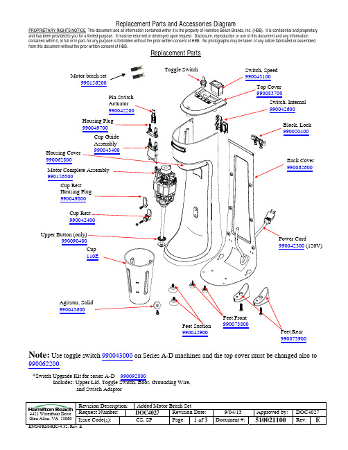
PROPRIETARY RIGHTS NOTICE This document and all information contained within it is the property of Hamilton Beach Brands, Inc. (HBB). It is confidential and proprietary and has been provided to you for a limited purpose. It must be returned or destroyed upon request. Disclosure, reproduction or use of this document and any information contained within it, in full or in part, for any purpose is forbidden without the prior written consent of HBB. No photographs may be taken of any article fabricated or assembled from this document without the prior written consent of HBB.
Replacement Parts
Motor brush set 990156200
Pin Switch Actuator 990042200
Housing Plug 990049700
Housing Cover 990062800
Cup Guide Assembly 990043400
海尔(Haier)下装机械洗衣机说明书
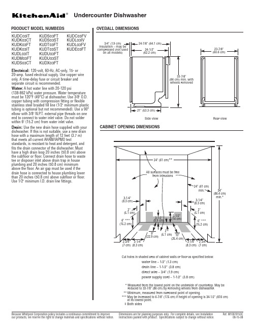
Undercounter DishwasherPRODUCT MODEL NUMBERSKUDC03IT KUDK03CT KUDK03FT KUDK03IT KUDL03IT KUDM03FT KUDS03CTKUDS03FT KUDS03ST KUDT03FT KUDT03ST KUDU03FT KUDU03ST KUDX03FTKUDC03FV KUDL03IV KUDL03FV KUDE03FTElectrical:120-volt, 60-Hz, AC-only, 15- or 20-amp. fused electrical supply. Use copper wire only. A time-delay fuse or circuit breaker and separate circuit is recommended.Water:A hot water line with 20-120 psi(138-862 kPa) water pressure. Water temperature must be 120°F (49°C) at dishwasher. Use 3/8" O.D.copper tubing with compression fitting or flexible stainless steel braided fill line (1/2" minimum plastic tubing is optional but not recommended). Use a 90°elbow with 3/8" N.P .T. external pipe threads on one end to connect to water inlet valve. Do not solder within 6" (15.2 cm) from water inlet valve.Drain:Use the new drain hose supplied with your dishwasher. If this is not suitable, use a new drain hose with a maximum length of 12 feet (3.7 m) that meets all current AHAM/IAPMO teststandards, is resistant to heat and detergent, and fits the drain connector of the dishwasher. Must have a high drain loop 20 inches (50.8 cm) above the subfloor or floor. Connect drain hose to waste tee or disposer inlet above drain trap in house plumbing and 20 inches (50.8 cm) minimum above the floor. An air gap must be used if the drain hose is connected to house plumbing lower than 20 inches (50.8 cm) above subfloor or e 1/2" minimum I.D. drain line fittings.3/4" (1.9 cm)on all models)Side viewRear viewCut holes in shaded area of cabinet walls or floor as specified below:water line – 1/2" (1.3 cm)drain line – 1-1/2"(3.8 cm)direct wire – 3/4" (1.9 cm)power supply cord – 1-1/2"(3.8 cm)* Measured from the lowest point on the underside of countertop. May be reduced to 33-7/8" (86 cm) by removing wheels from dishwasher.** Minimum, measured from narrowest point of opening.*** May be increased to 6-7/8" (17.5 cm) if height of opening is 34-1/2" (87.6 cm)at its lowest point.‡ Both sides(8.3 cm)(7 cm)(8.3 cm)(7 cm)®。
家用变频一拖多(双压机)功能规格书5.5

M D V(家用变频一拖多)室外机功能规格书M D V(家用变频一拖多)室外机(东芝Two in one压缩机)功能规格书型号:MDV-J140W-511V 5.5编制:日期:审核:日期:会签:日期:在4.9版本基础上修改1、增加制冷时室外机的电子膨胀阀控制。
2、取消制热均油运行程序,但保留制冷运行程序在5.0版本基础上修改1、增加制热时室外机的电子膨胀阀控制,并取消原来的控制。
2、更改室外机除霜时电子膨胀阀控制。
在5.1版本基础上修改1、在5.1版本基础上进行细节修改在5.2版本基础上修改1、在5.2版本基础上进行细节修改在5.3 版本的基础上,功能未作改动,仅修改了通讯。
1、增加机型识别码。
作为机型匹配标识,如果室内机接收到机型不匹配,则室内机报警,不能开启。
2、可以接收32位地址的室内机。
在5.4版本的基础上,修改了室内外通讯部分,当室内外机不匹配时,则显示室内机不匹配故障,详见蓝色字体1、适用范围本功能规格书适用于5匹家用变频一拖多空调系统室外机(1个变频压缩机{BH240X2CS-20KU}+1个定速压缩机{PH420X3CS-8KUC1})的功能说明。
适用机种: MDV-J120(140)W-5112、冷冻循环图2.1 压缩机采用美芝公司的变频旋转式压缩机以42HZ—120HZ运转,配合定速压缩机的启停,在同一个制冷系统内进行多级能量控制,满足对室内机进行的单独和线性控制。
2.2高低压力开关制冷系统高低压力保护用压力开关2.3高、低压储液罐储存暂时过多的制冷剂2.4油分离器保证系统在不同负荷下压缩机的及时回油2.5 室外机电子膨胀阀EXV制热运行时调节系统过热度,起节流降压用2.6 电磁阀SV1SV1为定速压缩机启动卸载用2.7 电磁阀SV2制热时用,和主四通阀控制一致 28辅助四通阀SV3开定速压缩机时用,控制接在定速压缩机接触器的反向触点上3、控制系统的概况本控制系统的设计采用模块化的设计思路,内机与外机的控制系统的结构采用如下图所示的的主从结构。
海尔全自动滚筒洗衣机说明书
窗帘 7
XQG70-HBX12266 SN XQG70-HBX12288
超柔 2
0
8
窗帘
7
67
6
8 10 2
超柔
70-HBX12266 SN
窗帘
窗帘
3 用户使用的洗涤程序。
由
排水阀内掉入硬币、发卡等异 物导致阀塞不封水而边进边排 (清除异物)
超柔
是否过高(应小于5cm) (放平排水管,清除异物)
排水阀
异常报警 异常报警
75
下可打开机门;若水位高于观察窗下沿, 则需要打开洗衣机底部小门,将一个盛水 容器放于流尽管处,拔掉管堵将水排出, 待水位低于观察窗下沿可打开机门。开机 门时,需要向下拉动底部小盒内的拉杆, 拉住拉环向下轻拉,听到轻微的响声后, 可打开机门并添加衣物或取出衣物,之后 将底部小门复位。
消毒剂 (用户有需求的情况下使用)
(用户有需求的情况下使用)
必须为国家认证的合格产品。
XQG70-HBX12266 SN
XQG70-HBX12288
50 70
0020507213K
防溅板
防溅板
防溅板
安装外排水管
取下护套上 的橡胶软堵
5 cm
用手握住外排 水管前端,将 其插入排水连 接护套内。
5 cm 。
5
5 洗衣机距离墙至少5cm
外排水管
进水管总成
防溅塑料堵
变频一拖(三、四)风管机说明书J

变频一拖三(四)空调控制器设计说明书拟制:审核:批准:编号:杭州五海变频电控技术有限公司一、主要技术性能指标1、采用模糊控制完成室温的调节,压缩机采用交流变频压缩机,实行变频控制,变频范围为30-120HZ(根据压缩机定)。
2、电源为220V、50HZ,电压范围150-260V,功率因数>98%。
3、使用条件:环境温度-15~+55℃,相对湿度45-85%。
4、温度控制精度:±0.5℃。
5、时间误差:小于0.1%。
6、控制器符合GB5956-96、GB7725-96、GB3797-87;印刷线路板符合GB4588.1和GB4588.2;电磁兼容性符合国家有关标准要求。
二、主要功能遥控器1、开关机操作。
2、选择运转方式:自动、制冷、制热、除湿、送风。
3、选择室内机风扇速度:高速、中速、低速、自动风速。
4、设定室内温度:制冷运转时:16℃—30℃,初始值24℃;制热运转时:16℃—30℃,初始值24℃;抽湿运转时:16℃—30℃,初始值24℃;通风运转时:16℃—30℃,初始值24℃;自动运转时:16℃—30℃,初始值24℃;5、自动睡眠方式:按键打开/关闭。
6、选择定时运转:设定1—12小时的开机/关机时间定时器。
7、设定/取消定时运转,设定/取消已定时的定时器。
8、控制风向。
9、高效/节约运行。
室内机室内机可选用壁挂机、柜机、风管机等。
1、五种运转方式:自动、制冷、制热、除湿、送风。
2、定时功能。
3、感测室内温度、室内热交换器盘管温度、内机进口温度、出口温度。
4、时间延迟安全控制:在压缩机停机再启动时要延时3分钟保护。
(初次上电时无时间延迟安全控制)5、室内机风扇速度控制:制冷:高、中、低速;制热:高、中、低、微速。
6、显示:工作状态和故障显示。
7、电子膨胀阀的控制。
8、除湿运转方式。
9、室内热交换器盘管过热保护。
10、制冷运转时室内热交换器防结霜保护。
11、自动运转。
12、控制风向:根据遥控器信号控制风向。
海尔电子产品:海尔洗碗机指南书说明书

washers. Remove large remnants of food from 3. Switch on the appliance .
the tableware. Check that the spray arms can ro-
4. Select the programme. 5. Start the programme . 6. Remove the tableware at the end of the pro-
6. Re-assemble the filter system.
7. Insert the filter system into the appliance and turn the coarse filter clockwise. Make sure that the arrow markings match up.
spoon and grip it by the crosspiece.
5. Lift the pump cover inwards at an angle and remove.
6. Remove any remnants of food and foreign bodies in the area
Programme
1) Duration [h:min] 2) Energy [kWh] 3) Water [l]
Intensive 70°
1) 2:05 - 2:15 2) 1,350 - 1,400 3) 10,5 - 13,5
Auto 45-65°
1) 1:40 - 2:45 2) 0,850 - 1,450 3) 7,0 - 15,5
1) 0:15 - 0:15 2) 0,050 - 0,050 3) 4,0 - 4,0
【精编范文】海尔中央空调说明书-实用word文档 (3页)

本文部分内容来自网络整理,本司不为其真实性负责,如有异议或侵权请及时联系,本司将立即删除!== 本文为word格式,下载后可方便编辑和修改! ==海尔中央空调说明书篇一:室内机型号 - 海尔中央空调海尔双变多联四面出风嵌入式空调注:以上参数仅供参考,实际以机器铭牌为准!海尔双变多联四面出风嵌入式空调注:以上参数仅供参考,实际以机器铭牌为准!本技术参数版权所有:中央空调在线 / 本站网络技术支持:虎酋网络http://篇二:海尔中央空调线控器征明海尔中央空调线控器火热征名,期待你的参与!曾经的我们,为了给用户全面的功能体验,全面的按钮设计就是产品的核心,产品型号就是线控器的名称,产品外观如下图;现在的我们,选择给用户最佳的使用体验,设计一款能读懂用户心的控制器,它能自学习你的使用习惯,它有老人、儿童的模式,它还有颠覆的操作界面……产品外观如下图。
它是中央空调控制器,它是互联网的产品;这就是它的外观,我们正为它火热征名,期待你来参与产品命名投票!A. 小黑氪(赋予产品人性化色彩,聪明、懂你)B. 小极氪(赋予产品人性化色彩,并且很萌,易记忆)C. 睿智(聪颖明智,表意积极向上,体现产品本身智能特性)D. 陪伴星(犹如月亮之于地球,时刻相伴,成为你生活中不可或缺的一部分)E. 智控伙伴/精灵(科技与人性的完美结合,更懂你的产品)F. 空气伙伴(易于产生产品功能联想,亲切友好)G. 其他1.请选出你觉得最符合我们产品形象的名字!2.如果你觉得都配不上我们的控制器形象,给出您的建议吧!篇三:海尔中央空调使用寿命价值不菲的家用中央空调到底值不值?鉴于中央空调拥有工作舒适、与装修相交融、漂亮大方等一些传统空调不具备的优势,不少人都期待夏日能够运用中央空调。
但中央空调造价不菲,这使得咱们在采购中央空调的时候分外慎重,常常会情不自禁的关心中央空调到底能用几年,这关系到咱们的购买回报率,那么中央空调能用多久呢,专家介绍:合理使用,各品牌家用中央空调的使用寿命都在15-20年,是传统柜、挂式空调的两倍,海尔中央空调使用寿命最低长达20年以上,高于同类产品其他品牌。
- 1、下载文档前请自行甄别文档内容的完整性,平台不提供额外的编辑、内容补充、找答案等附加服务。
- 2、"仅部分预览"的文档,不可在线预览部分如存在完整性等问题,可反馈申请退款(可完整预览的文档不适用该条件!)。
- 3、如文档侵犯您的权益,请联系客服反馈,我们会尽快为您处理(人工客服工作时间:9:00-18:30)。
本文部分内容来自网络整理,本司不为其真实性负责,如有异议或侵权请及时联系,本司将立即删除!
== 本文为word格式,下载后可方便编辑和修改! ==
海尔一拖多说明书
篇一:海尔H-MRV家用一拖多维修手册之调试
4.安装
4.1 设定内机地址
内机设定地址时,机号代码应在0-7之间且不重复,外机无需改动。
4.
4.3 以室外机为单位将连接的全部室内机组置于制冷试运行方式的功能.
以室外机为单位将连接的全部室内机组置于制热试运行方式的功能. (运行顺序)
4.4 制冷运转确认
篇二:海尔冰柜说明书
海尔冰箱bcd 195wt,矛盾的说明书201X-6-24 17:46
冰箱内的温度是通过温控器调节旋钮①来调节的。
旋钮上的刻度“0”是关机位置,“1,2,3,4,5,6,7”不代表具体的温度,数字越小,箱内温度越高;数字越大,则箱内温
度越低。
推荐:
1~3档环境温度≥30℃3~5档环境温度16~30℃5~7档环境温度≤16℃外界温度高室内冰箱才应该调低温度,比如外界30度冰箱内调为5度。
如果冬
天外界温度15度,冰箱要调成0度。
这是什么逻辑?难道冰箱里温度越低越
省电?那这样一年四季调零度好了 201X-6-24 19:17 满意回答首先要解释一下机械冰箱的控温原理,机械冰箱是通过冷藏室的温控器来控制整个冰箱
的温度的,制冷剂从冷冻流向冷藏,再回压机.就是说,冷冻室是间接通过冷藏来控制的,冷
藏温度达到后,制冷剂不再流动,冷冻室也不会再单独制冷。
明白了上面的原理后,就好解释你提的问题了.
1.夏天调低档是因为节电和保护压机。
举例说,如果你夏天调到5~7档,代表冰箱冷藏要维持一个很低的温度才会停机,而夏
天环境温度高,要维持这个温度很难,所以压机会一直长时间运转,不但于压机不利,而且
也不节能。
2.冬天调高档是为了保持冷冻室内食物不容易变坏. 冬天,环境温度低,如果我们设定为低档,冰箱冷藏很容易就达到设定档位对应的温度,
所以压机会长时间不运转,而这个结果就导致了冷冻室温度上升,我们知道,一般冷冻室温
度都在-12度以下,在这个温度下很多食物可存放很久,而如果压机很少运转的话,就很难
维持这个温度了。
所以我们要设定为高档.这也是为什么冬天要求打开冷藏室的温度补偿开关
的原因,就是想让冷藏室传感器附近的温度升高,这样压机就会启动,来维持冬天的时候冷
冻室的温度.如果理解了我上面的话,你就明白说明书的意思了,说明书并没有错.201X-6-24 18:03
没错的,冰箱其实就是一个能量转换过程,如果室内外温度相差太大,冰箱是很难进入
最佳工作状态。
如果外界温度为35度,你想要冰箱内达到-18度,可以达到,但是你需要压
缩机不停机长时间运转才行。
再者说了,大夏天
的,如果温度相差15度,你完全可以感到冰
霜的感觉,何必一定要把自己冻坏才好,想想你就会想通了。
呵呵! 201X-6-24 18:03 知为力
海尔冰箱bcd 195wt,说明书不矛盾。
“1,2,3,4,5,6,7”是冰箱调温档位。
冰箱调温1档--7档数字越大温度越低。
夏天将冰箱调到2-3档。
原因:在夏季,环境
温度较高,冷冻室内温度若打在强挡,内外温度差大,因此箱内温度每下降1℃都很困难,
再则,通过箱体保温层和门封冷气散失也会加快,这样开机时间很长而停机时
间很短,会
导致压缩机在高温下长时间运转,既耗电又易损坏压缩机。
旋钮上的刻度“0”是低温补偿开关。
冬季环境温度低时用的功能,夏季不需要使用该功
能。
201X-6-24 21:07
你好,向您这样的问题我买冰箱看说明书的时候也遇到过的。
我选择的也是海
尔的,现
在用了三年多了,一直很好用的。
我当时是咨询大售后电话才明白的。
夏天抵
挡不仅可以延
长压缩机的使用时间还可以省电的。
冬天保持食物的的新鲜。
祝您万事如意。
海尔bc-117fc
产品点评发表于 201X-10-09 10:03 评价:优点:冰箱内部合理布局,小身材
大冷藏,小巧不占地方。
采用科学的深度。
大容量,
可存放大量新鲜水果蔬菜。
设有微冻室,适合冷藏短期内食用的物品,还可快
速制冰,享受
新鲜。
灵巧的冰箱,适度的制冷功率,超低耗电。
不足:地盘太低,没后盖,
容易进水,如果搞卫生时不注意就危险啦。
总结:一款节能、实用、小巧的
冰箱 haier 海尔bc-117fc冰箱的制冷剂到底是什么?201X-4-2 15:37
我在网上看到的是说r600a,可是冰箱买回来时苏宁的送货人员告诉我是氟里昂... 好
迷茫 201X-4-2 16:37 满意回答制冷剂是r134a。
r-134a是中低温环保制冷剂,由于hfc-134a良好的综合性能,使其成
为一种非常有效和安全的cfc-12的替代品,主要应用于在使用r12制冷剂的多数领域,包括:
冰箱、冷柜、饮水机、汽车空调、中央空调、除湿机、冷库、商业制冷、冰水机、冰淇淋机、
冷冻冷凝机组等制冷设备中,同时还可应用于气雾推进剂、医用气雾剂、杀虫
药抛射剂、聚。