USB转通用串口线使用手册
FTDI USB 转串口适配器说明书
Future Technology Devices International Limited (FTDI)Unit1, 2 Seaward Place, Centurion Business Park,, Glasgow G41 1HH United KingdomTel.: +44 (0) 141 429 2777 Fax: + 44 (0) 141 429 2758E-Mail (Support): ********************* Web: Copyright © 2010 Future Technology Devices International LimitedNeither the whole nor any part of the information contained in, or the product described in this manual, may be adapted or reproduced in any material or electronic form without the prior written consent of the copyright holder. This product and its documentation are supplied on an as-is basis and no warranty as to their suitability for any particular purpose is either made or implied. Future Technology Devices International Ltd will not accept any claim for damages howsoever arising as a result of use or failure of this product. Your statutory rights are not affected. This product or any variant of it is not intended for use in any medical appliance, device or system in which the failure of the product might reasonably be expected to result in personal injury. This document provides preliminary information that may be subject to change without notice. No freedom to use patents or other intellectual property rights is implied by the publication of this document. Future Technology Devices International Ltd, Unit1, 2 Seaward Place, Centurion Business Park, Glasgow, G41 1HH, United Kingdom. Scotland Registered Number: SC136640Future Technology Devices International LtdUSB to RS422 Serial Converter CableDatasheetDocument Reference No.: FT_000116Version 1.2Issue Date: 18-01-20101 DescriptionThe USB-RS422 cable is a USB to RS422 levels serial UART converter cable incorporating FTDI’sFT232RQ USB to serial UART interface IC device which handles all the USB signalling and protocols. The cable provides a fast, simple way to connect devices with a RS422 interface to USB.Each USB-RS422 cable contains a small internal electronic circuit board, utilising the FT232R, which is encapsulated into the USB connector end of the cable. The FT232R datasheet, DS_FT232R , is available at . The integrated electronics also include the RS422 transceiver plus Tx and Rx LEDs which give a visual indication of traffic on the cable (if transparent USB connector mould specified). The other end of the cable is bare, tinned wire ended connections by default, but can be customised using different connectors to support various applications. Cables are FCC, CE, RoHS compliant.The USB side of the cable is USB powered and USB 2.0 full speed compatible. Each cable is 1.8m long and supports a data transfer rate up to 3 Mbaud. Each cable supports the FTDIChip-ID™, with a unique USB serial number programmed into the FT232R. This feature can be used to create a security orpassword protected file transfer access using the cable. Further information and examples on this feature are available at under FTDIChip-ID Projects .The USB-RS422 cables require USB drivers, available free from , which are used to make the FT232R in the cable appear as a virtual COM port (VCP). This then allows the user to communicate with the USB interface via a standard PC serial emulation port (for example TTY). Another FTDI USB driver, the D2XX driver, can also be used with application software to directly access the FT232R on the cable though a DLL. This is illustrated in the Figure 1.1Virtual COM PortSoftware application access to USB via D2XX DriverCustomised connectorsOptionsOptionsCustomised connectorsFigure 1.1 Using the USB-RS422 Cable2 Cable Part NumbersThe following table gives details of the available USB-RS422 cables.Table 2.1 Available USB-RS422 cables.Table 2.1 USB-RS422 Cables Descriptions and Part Numbers*FTDI supports customised end connector designs. For more information, please contact FTDI Sales Team (*******************)2.1 CertificationsFTDI USB-RS422 cable is fully RoHs compliant as well as CE and FCC certified.Table of Contents1Description (1)2Cable Part Numbers (2)2.1Certifications (2)3Typical Applications (4)3.1Driver Support (4)3.2Features (5)4Features of FT232R applicable to USB-RS422 Cable (6)5USB-RS422-WE-LLLL-CU (7)5.1USB-RS422-WE Connections and Mechanical Details (7)5.2USB-RS422-WE Cable Signal Descriptions (8)5.3USB-RS422-WE Electrical Parameters (8)6Cable PCB Block Diagram (10)7USB-RS422 Schematic (11)8Contact Information (12)Appendix A - Cable EEPROM Configuration (14)Appendix B - List of Figures and Tables (15)Appendix C - Revision History (16)3Typical ApplicationsUSB to serial RS422 level converter. Upgrading legacy peripherals to USB. Interface Microcontroller UART or I/O to USB. Interface FPGA or PLD to USB. USB Instrumentation PC interface. USB industrial control.USB password protected file transfers.3.1Driver SupportRoyalty free VIRTUAL COM PORT(VCP) DRIVERS for...Windows 7 64-bitWindows 98, 98SE, ME, 2000, Server 2003, and Server 2008Windows XP and XP 64-bitWindows Vista and Vista 64-bitWindows XP EmbeddedWindows CE 4.2, 5.0 and 6.0Mac OS 8/9, OS-XLinux 2.4 and greater Royalty free D2XX Direct Drivers(USB Drivers + DLL S/W Interface)Windows 7 64-bitWindows 98, 98SE, ME, 2000, Server 2003, and Server 2008Windows XP and XP 64-bitWindows Vista and Vista 64-bitWindows XP EmbeddedWindows CE 4.2, 5.0 and 6.0Linux 2.4 and greaterMac OS-XThe drivers listed above are all available to download for free from . Various 3rd Party Drivers are also available for other operating systems - see for details.3.2FeaturesUSB-RS422 converter cable provides a USB to RS422 serial interface with customised end connectors.Entire USB protocol handled by the electronics in the cable.EIA/TIA-422communication interface with low power requirements.UART interface support for 7 or 8 data bits, 1 or 2 stop bits and odd / even / mark / space / no parity.Internal EEPROM with user writeable area. FTDI’s royalty-free VCP allow for communication as a standard emulated COM port and D2XX ‘direct’ drivers provide DLL application programming interface.Visual indication of Tx and Rx traffic via LEDs in the transparent USB connector. X-On / X-Off software handshaking.Data transfer rates from 300 baud to 3 Mbaud. Support for FT232R FTDIChip-ID™ feature for improved security.Low USB bandwidth consumption.UHCI / OHCI / EHCI host controller compatible. USB 2.0 Full Speed compatible.-40°C to +85°C operating temperature range. Cable length is 1.80m (6 feet).ESD Protection for RS-422 I/O's±15kV Human Body Model (HBM)±15kV EN61000-4-2 Air Gap Discharge±8kV EN61000-4-2 Contact DischargeFCC and CE compliant.Custom versions available on request (subject to MOQ).RoHS Compliant4Features of FT232R applicable to USB-RS422 CableThe USB-RS422 cable uses FTDI’s FT232RQ USB to serial UART IC device. This section summarises the key features of the FT232RQ which apply to the USB-RS422 USB to serial RS422 converter cables. For further details, and a full features and enhancements description consult the FT232R datasheet. This is available from .Internal EEPROM. The internal EEPROM in each cable is used to store USB Vendor ID (VID), Product ID (PID), device serial number, product description string and various other USB configuration descriptors. Each cable is supplied with the internal EEPROM pre-programmed as described in Appendix A – Cable EEPROM Configuration. The internal EEPROM descriptors can be programmed in circuit, over USB without any additional voltage requirement. It can be programmed using the FTDI utility software called MPROG, which can be downloaded from FTDI Utilities on the FTDI website (). Additionally, there is a user area of the internal EEPROM available to system designers to allow storing of data (note that this is not modified by MPROG).Lower Operating and Suspend Current. The FT232R has a low 15mA operating supply current and a very low USB suspend current of approximately 70μA. (Note that during suspend mode, the current drawn by any customised cable application which uses the USB supply, should not exceed 2.5mA to remain USB compliant)Low USB Bandwidth Consumption. The USB interface of the FT232R, and therefore the USB-RS422 cables has been designed to use as little as possible of the total USB bandwidth available from the USB host controller.FTDIChip-ID™. The FT232R includes the new FTDIChip-ID™ security dongle feature. This FTDIChip-ID™ feature allows a unique number to be burnt into each cable during manufacture. This number cannot be reprogrammed. This number is only readable over USB can be used to form the basis of a security dongle which can be used to protect any customer application software being copied. This allows the possibility of using the USB-RS422 cables as a dongle for software licensing. Further to this, a renewable license scheme can be implemented based on the FTDIChip-ID™ number when encrypted with other information. This encrypted number can be stored in the user area of the FT232R internal EEPROM, and can be decrypted, then compared with the protected FTDIChip-ID™ to verify that a license is valid. Web based applications can be used to maintain product licensing this way. An application note, AN232R-02, available from FTDI website () describes this feature.Improved EMI Performance. The USB-RS422 cables are FCC and CE certified.Extended Operating Temperature Range - The USB-RS422 cables are capable of operating over an extended temperature range of -40º to +85º C thus allowing them to be used in commercial or industrial applications.5USB-RS422-WE-LLLL-CUThe USB-RS422-WE cable is un-terminated; it has bare and tinned wires.The LLLL specifies the length of the cable in cm. The CU specifies the colour of the cable and the colour of the USB connector. The cable can be either Black or transparent. The USB connector comes with transparent plug because of the LED implemented inside but can be sold in black colour as well. For simplicity, the LLLL and CU have been dropped from the following descriptions.5.1USB-RS422-WE Connections and Mechanical DetailsThe following Figure 5.1 shows the cable signals and the wire colours for the signals on the USB-RS422-WE cable. The Figure 5.2 shows dimensions in millimetres.BLACKBROWNREDORANGEYELLOWGREENBLUEWHITEGREY230Figure 5.2 USB-RS422-WE Mechanical Details (dimensions in mm)Figure 5.3 USB-RS422-WE Cable images5.2USB-RS422-WE Cable Signal Descriptions5.3USB-RS422-WE Electrical Parameters* - The 54 ohms is the equivalent of two 120 ohm termination resistors placed on each side of the transmission line and the input impedance of 32 receivers on the line.6Cable PCB Block DiagramThe block diagram for the small internal electronic circuit board, utilising the FTDI FT232R, which is encapsulated into the USB connector end of the cable, is shown in Figure 6.1.Customised versions of the cable are also available. Users interested in customised versions of these cablesshouldcontactFTDIsales(*******************).Wire Ended Figure 6.1 Block diagram of PCB Used in the USB to RS422 Serial Converter Cable7USB-RS422 SchematicThe detailed schematic of Converter Cable USB-RS422 is shown on figure 7.1Figure 7.1 Schematic for USB-RS422 Converter CableDocument Reference No.: FT_000116USB TO RS422 SERIAL CONVERTER CABLE DatasheetVersion 1.2Clearance No.: FTDI# 74 8Contact InformationHead Office – Glasgow, UKFuture Technology Devices International LimitedUnit 1, 2 Seaward Place, Centurion Business ParkGlasgow G41 1HHUnited KingdomTel: +44 (0) 141 429 2777Fax: +44 (0) 141 429 2758Tel: +44 (0) 141 429 2777Fax: +44 (0) 141 429 2758E-mail (Sales) *******************E-mail (Support) *********************E-mail(GeneralEnquiries)*******************Web Site URL Web Shop URL Branch Office – Shanghai, ChinaFuture Technology Devices International Limited (China)Room 408, 317 Xianxia Road,ChangNing District,ShangHai, ChinaTel: +86 (21) 62351596Fax: +86(21) 62351595E-Mail(Sales):*********************E-Mail(Support):***********************E-Mail(GeneralEnquiries):**********************Web Site URL: Branch Office – Taipei, TaiwanFuture Technology Devices International Limited (Taiwan)2F, No. 516, Sec. 1, NeiHu RoadTaipei 114Taiwan , R.O.C.Tel: +886 (0) 2 8791 3570Fax: +886 (0) 2 8791 3576E-mail (Sales) **********************E-mail (Support) ************************E-mail(GeneralEnquiries)**********************Web Site URL Branch Office – Hillsboro, Oregon, USAFuture Technology Devices International Limited (USA)7235 NW Evergreen Parkway, Suite 600Hillsboro, OR 97123-5803USATel: +1 (503) 547 0988Fax: +1 (503) 547 0987E-Mail (Sales) *********************E-Mail(Support)*********************Web Site URL Distributor and Sales RepresentativesPlease visit the Sales Network page of the FTDI Web site for the contact details of our distributor(s) and sales representative(s) in your country.Vinculum is part of Future Technology Devices International Ltd. Neither the whole nor any part of the information contained in, or the product described in this manual, may be adapted or reproduced in any material or electronic form without the prior written consent of the copyright holder. This product and its documentation are supplied on an as-is basis and no warranty as to their suitability for any particular purpose is either made or implied. Future Technology Devices International Ltd will not accept any claim for damages howsoever arising as a result of use or failure of this product. Your statutory rights are not affected. This product or any variant of it is not intended for use in any medical appliance, device or system in which the failure of the product might reasonably be expected to result in personal injury. This document provides preliminary information that may be subject to change without notice. No freedom to use patents or other intellectual property rights is implied by the publication of this document. Future Technology Devices International Ltd, Unit 1, 2 Seaward Place, Centurion Business Park, Glasgow G41 1HH United Kingdom. Scotland Registered Number: SC136640Appendix A - Cable EEPROM ConfigurationEach USB-RS422 cable is controlled by the FTDI FT232R IC. This FT232R device contains an EEPROM which contains the USB configuration descriptors for that device. When the cable is plugged into a PC or a USB reset is performed, the PC will read these descriptors. The default values stored into the internalThe internal EEPROM in the cable can be re-programmed over USB using the utility program MPROG. MPROG can be downloaded from the . Version 2.8a or later is required for the FT232R chip. Users who do not have their own USB Vendor ID but who would like to use a unique Product ID in their design can apply to FTDI for a free block of unique PIDs. Contact FTDI support for this service.Appendix B - List of Figures and TablesList of FiguresFigure 1.1 Using the USB-RS422 Cable (1)Figure 5.1 USB-RS422-WE Connections (7)Figure 5.2 USB-RS422-WE Mechanical Details (dimensions in mm) (7)Figure 5.3 USB-RS422-WE Cable images (7)Figure 6.1 Block diagram of PCB Used in the USB to RS422 Serial Converter Cable (10)Figure 7.1 Schematic for USB-RS422 Converter Cable (11)List of TablesTable 2.1 USB-RS422 Cables Descriptions and Part Numbers (2)Table 5.1 USB-RS422-WE Cable Signal Descriptions (8)Table 5.2 USB-RS422-WE I/O Characteristics (8)Table 5.3 USB-RS422-WE ESD Tolerance (9)Table 0.1 Default Internal EEPROM Configuration (14)Appendix C - Revision HistoryVersion Draft First Draft Jan 2009 Version 1.0 11th Feb 2009 Version 1.1 Added and corrected images 14th May 2009Version 1.2 Changed TT to BT (Transparent to Black cable). 18th January 2010 Added Window 7 support。
USB转串口配置及驱动安装说明

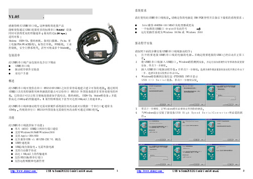
Model: UT-886USB/RS-232 商业级接口转换器使 用 说 明 书一、概述-------------------------------------------------- 二、主要功能-------------------------------------------- 三、 硬件安装及应用------------------------------------- 四、性能参数--------------------------------------------- 五、 连接器和信号---------------------------------------- 六、 产品外形和通信连接示意图----------------------- 七、 故障及排除 ------------------------------------------ 八、 产品外 观 图------------------------------------------2 2 2 334 5 5九、 安装驱动程序步骤------------------------------- 6-13一、 概述随着PC产业的不断发展,USB接口正在逐渐替代老式PC的各种低速外围接口,然而 目前工业环境中许多重要的设备仍然使用RS-232接口界面设计,因此许多用户使用USB 到RS-232转换器来实现PC机与RS-232设备之间的数据传输。
UT-886是一款通用的USB/RS-232转换器,无需外加电源、兼容USB、RS-232标 准 , 能 够 将 单 端 的USB信 号 转 换 为RS-232信 号 , 转 换 器 内 部 带 有 零 延 时 自 动 收 发 转 换, 独 有 的I/O电 路 自 动 控 制 数 据 流 方 向, 即 插 即 用. 确 保 适 合 一 切 现 有 的 通 信 软 件 和 接 口 硬 件。
USB TO RS232 485 TTL 用户手册说明书
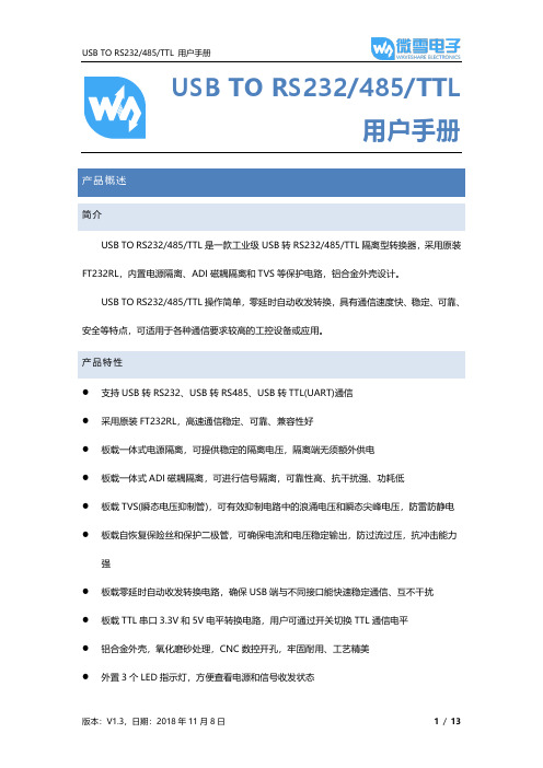
USB TO RS232/485/TTL用户手册产品概述简介USB TO RS232/485/TTL是一款工业级USB转RS232/485/TTL隔离型转换器,采用原装FT232RL,内置电源隔离、ADI磁耦隔离和TVS等保护电路,铝合金外壳设计。
USB TO RS232/485/TTL操作简单,零延时自动收发转换,具有通信速度快、稳定、可靠、安全等特点,可适用于各种通信要求较高的工控设备或应用。
产品特性⚫支持USB转RS232、USB转RS485、USB转TTL(UART)通信⚫采用原装FT232RL,高速通信稳定、可靠、兼容性好⚫板载一体式电源隔离,可提供稳定的隔离电压,隔离端无须额外供电⚫板载一体式ADI磁耦隔离,可进行信号隔离,可靠性高、抗干扰强、功耗低⚫板载TVS(瞬态电压抑制管),可有效抑制电路中的浪涌电压和瞬态尖峰电压,防雷防静电⚫板载自恢复保险丝和保护二极管,可确保电流和电压稳定输出,防过流过压,抗冲击能力强⚫板载零延时自动收发转换电路,确保USB端与不同接口能快速稳定通信、互不干扰⚫板载TTL串口3.3V和5V电平转换电路,用户可通过开关切换TTL通信电平⚫铝合金外壳,氧化磨砂处理,CNC数控开孔,牢固耐用、工艺精美⚫外置3个LED指示灯,方便查看电源和信号收发状态⚫高品质USB-B和RS232接口材料,插拔顺畅,坚固可靠产品参数⚫产品类型:工业级光电隔离型转换器⚫通信速率:300-921600bps⚫主机接口:USB⚫设备接口: RS485/RS232/TTL⚫USB接口:◼工作电平:5V◼接口形式:USB-B型接口◼接口保护:200mA自恢复保险丝,隔离输出◼传输距离:约5米⚫RS485接口:◼接口形式:接线端子◼接口引脚:A+、B-、GND◼方向控制:硬件自动判别和控制数据传输方向◼接口保护:提供600W防雷、浪涌和15KV静电保护(预留120R平衡电阻焊盘) ◼传输距离:约1200米◼传输模式:点对多(至多32个节点,16个节点以上建议加中继器)⚫RS232接口:◼接口形式:DR9 公口◼接口保护:TVS管保护,浪涌和静电保护◼传输距离:约15米◼传输模式:点对点◼TTL(UART)接口:◼工作电平:3.3V或5V◼接口形式:接线端子◼接口引脚:TXD、RXD、GND◼接口保护:提供钳位保护二极管,防过压负压,抗冲击干扰◼传输模式:点对点⚫指示灯:◼PWR:电源指示灯,接入USB,检测到电压则亮红灯◼TXD:发送指示灯,有数据从USB口发出时亮绿灯◼RXD:接收指示灯,有数据从设备接口发回时亮蓝灯⚫使用环境:◼温度范围:-15℃~ 70℃◼湿度范围:5%RH ~ 95%RH⚫操作系统:Windows 10 / 8.1 / 8 / 7 / XP备注:RS485(板载预留120R平衡电阻焊盘,客户可以根据通讯数量考虑是否加入,建议在起止端加入也就是主机和最后一个设备上面各加一个120Ω的匹配电阻。
ARB-0612 USB转RS232 422 485 485-4W TTL转换器手册说明书
ARB-0612Converter USB – RS 232/422/485/485-4W/TTLManualARB-0612_v1_01Update date:10/2018r.Symbols & Marks (3)General installation and safety rules (3)1.Destination of device (4)2.Device parameters (5)2.1.Technical parameters (5)2.2.Description of connectors (6)2.3.Block diagram (8)2.4.Dimensions (8)3.Wiring (9)4.Instalation (10)4.1.Installation of USB drivers (10)4.2.Changing the COM port assignment in Windows (11)4.3.Exploitation (14)5.Contact details (14)General installation and safety rulesThe device should be installed in accordance with this manual.The fulfillment of this condition is the basis for ensuring safety and correct operation of the device. The fulfillment of this condition is the basis for ensuring safety and correct operation of the device.The manufacturer is not liable for damages resulting from using the device in the wrong way or not according to the purpose.Modifications to the device are not allowed and can be a source of danger.The ARB-0612 converter converts the USB signal into a serial communication standard RS232/RS422/RS485,RS485-4W/TTL-3.3,TTL-5V. The device is powered directly from the USB port. The converter supports two RS485 standards (2-wire and 4-wire), can act as HUB USB to 2xRS485 2-wire.Works with32 and 64bit operating systems.Remember to use the appropriate drivers. The device is intended for the USB 2.0 standard. When connected to the 3.0 standard, the converter works as if it was connected to the standard 2.0. It is possible to choose one of four serial transmission standards, i.e. RS232, RS422, RS485 or TTL. The converter provides 1500V, 2500V, 3000V or 5000V isolation between the USB port and the other serial ports. In addition, the RS422 and RS485 port has overvoltage protection. The operating system creates a virtual COM serial port that can be used by applications as an ordinary COM port. The user has the option of assigning a different COM port number than the one that automatically assigned the system. All parameters of the COM port (for example: baudrate, parity check), are determined by the application using the converter ARB-0612.Application:–Protecting your PC or laptop from overvoltages and from damage that may occur when using serial communications.–Creating or adding an additional serial port from 1 to 256.–The RS232 port is equipped with all transmission and reception lines, which allows for safe programming of controllers and other devices requiring serial communication and using additional RS232 port signals.–The ARB-0612 converter has an internal reset signal, thus it can be used for permanent operation in applications that have the option of automatically rebuilding the serial port.2.1.Technical parametersTechnical parameters of the converter are presented in Table 2.1.1.2.2.Description of connectorsThe view of the ARB-0612 converter is shown in Figure 2.2.1. A description of its connectors is presented in Table 2.2.1. A description of the function of connectors, DB9 sockets, dip-switch and LED indicators is presented in Table 2.2.2.Fig. 2.2.1. View of the converter ARB-0612Male socket- A denotes the D + line, B denotes the D - line.** - switch operations must be carried out in pairs.*** - OFF position - active RS485; ON position - active RS422 / RS485-4W.The block diagram of the ARB-0612 converter is shown in Figure 2.3.1.Fig. 2.3.1. Block diagram of ARB-06122.4.DimensionsDimensions of the ARB-0612 converter are shown in Figure 2.4.1.Fig. 2.4.1. Dimensions of the ARB-0612Table 2.5.1 presents the available versions with catalog numbers.3.WiringThe device should be connected to a computer using a USB cable. One of the selected RS232, RS422, RS485, RS485-4W or TTL ports should be selected. The method of connecting the RS port is shown in Figure 3.1.USB/RS422,485-4W USB/RS232USB/TTLPołączenie Null Modem3-TxD2-RxD5-GND*opis połączenia null modem wtab. 3.1Fig. 3.1. The method of connecting the RS ports.4.Instalation4.1.Installation of USB driversBefore you start the proper operation, you must install the appropriate USB drivers on the computer with which the converter should work. The type of drivers depends on the operating system installed on your computer.The drivers and instructions for installing them are available at: /FTDrivers.htm.To change the assignment of the COM port, it is necessary to start the Device Manager while the converter ARB-0612is connected from the USB side to the computer.Menu: Start->Control Panel->System->Hardware->Device ManagerSelect USB Serial Port whose settings you want to change.Press the right mouse button and select Properties from the expanded menu.In the Port Settings tab, please select Advanced options ...In case the selected port is already occupied by another device,the following message will appear:If you have to use this port, press YES4.3.ExploitationAfter correct installation of the drivers and connecting the converter to the USB port in the device manager should be visible COM port assigned to the converter. The device is signaled by sound and blinking of DL and UL diodes. The PWR diode should be permanently illuminated.5.Contact detailsASPAR s.c.ul. Oliwska 112,80-209 Chwaszczyno, POLANDphone +48 58 351-39-89; +48 58 732-71-73****************www.ampero.eu。
USB转串口线 驱动安装及使用说明
1.说明:下面的操作步骤只适用于UT-810型号的USB转串口黑色线缆;
2.安装驱动程序
⏹情况1:安装文件在光盘上,假设光盘的驱动符为E,点击E盘盘符,
依次进入下面的目录E:\USB 1.1 TO RS232 Cable\PC Driver\Setup;
⏹找到安装文件98ME_20011_2kXP_20024 Driver Installer.exe双击,系统
弹出下面的对话框;
⏹单击下一步后系统弹出,“InstallShield Wizard 完成”对话框,表明驱动
已经安装完成;
⏹情况2:如果98ME_20011_2kXP_20024 Driver Installer.exe文件在硬盘
或者U盘上,找到对应的目录双击即可完成安装;
3.插上串口线
4.检查USB转串口的串口编号
在进行串口扩展之后,用户在使用“一控多”功能之前,应该先检查该PC 上共有多少个串口设备,基本步骤如下:
⏹在系统桌面上,选择我的电脑,单击鼠标右键;
⏹选择我的属性,然后弹出“系统属性”窗口;
⏹在系统属性窗口中,点击“硬件”选项后单击“设备管理器”按钮,弹
出“设备管理器”对话框;
⏹单击“端口(COM和LPT)”弹出“设备管理器”的对话框;
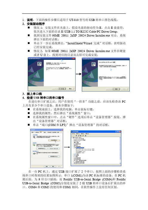
在一台PC机上,通过USB接口扩展了2个串口,按照上面的步骤检查系统串口时得到的结果如图所示,串口1(COM1)为该PC机标准的设备,在PC机箱后面,为9针公口插座;而Prolific USB-to-Serial Bridge (COM4)和Prolific USB-to-Serial Bridge (COM5)分别是安装了2根USB转串口设备后扩展出的串口。
COM4和COM5的使用和COM1相同,在软件操作上没有任何区别。
USB 转串口(RS232) 线 说明书V1.05
/
USB to Serial RS232 Cable User's Manual
1
系统要求
请在使用此USB转串口线线前 请确定你的电脑是IBM PC兼容型并具备以下最低的系统要求 l Intel兼容486DX4-100 MHz中央处理器或更高 l 一个标准的USB接口(4-pin)并有此符号 l 运行的操作系统为Windows 98/Me 或 Windows 2000
/
USB to Serial RS232 Cable User's Manual
3
5. 当提示你成功安装以后 请运行调制解调器 诊断 看看是否正常
驱动程序删除
按照下面的步骤从Windows系统里删除USB转串口线驱动程序 1. 从你的电脑上拔下USB转串口线 2. 运行USB转串口线驱动盘里的f t d i u n i n . e x e 程序 并按照提示进行 3. 重新启动计算机
F C C 声明
This device generates and uses radio frequency and may cause interference to radio and television reception if not installed and used properly. This has been tested and found to comply with the limits of a Class B computing device in accordance with the specifications in Part 15 of FCC Rules. These specifications are designed to provide reasonable protection against such interference in a residential installation. However, there is no guarantee that interference will not occur in a particular installation. If this device does cause harmful interference to radio or television reception, which can be determined by plugging the device in and out, the user can try to correct the interference by one or more of the following measures: l Reorient or relocate the receiving antenna. l Increase the separation between the device and receiver.
USB通用串口使用手册
USB轉通用串口線用戶手冊1.產品特色2. 系統需求3. 驅動程序的安裝 ( Win2K )4. 連接埠設置5. 設置串口線的端口產品特色•符合USB 1.1 規范•支持RS232 串口界面•超過1Mbps的數據傳輸速率•支持遠程喚醒和電源管理功能系統需求•IBM PC 486DX4-100 MHz CPU 或更高及其兼容機•可用的 USB 端口• CD-ROM 驅動器• Windows 2000驅動程序的安裝(WIN2K)請遵循如下步驟去安裝USB轉通用串口線的Window 2K驅動程序1. 打開電腦並確認USB端口可用且工作正常2. 在安裝驅動程式時,請不要在電腦上連接USB轉通用串口線3. 請雙擊"PL2303_Prolific setup.exe ",開始安裝4. 安裝完成之後,請把USB轉通用串口線插到USB端口上,系統將會檢測到它,並自動運行“尋找新增硬體精靈 ”幫助你設置新設備。
單擊“下一步”繼續;5. 單擊“下一步”繼續。
對於 Windows 2000來說,單擊“搜尋適當的裝置驅動程序檔案(建議選項)”6. 找到它的驅動程序之後,單擊“下一步”繼續安裝. Windows將復制所需的文件到你的電腦硬盤上27. 出現如下介面,說明已經安裝完驅動程序8. 檢查“裝備管理器”,你可以看到Prolific USB to Serial Comm Port (COM3)3.連接埠設置6. 在 Windows 98SE 下 , 請使用附帶光碟中的串口設置軟體來修改7. 在 Windows Me 、 Windows 2000 、 Windows XP 下,請按照如下步驟來修改:(1) 在 " 裝置管理員", 選擇" 按類型排序設備", 選擇"連接埠 (COM & LPT) ". (圖 1)4(圖 1)(2) 雙擊“Prolific USB-to- serial Comm port(COM3)” 進入“ 內容” . (圖 2)(圖 2)5(3) 選擇" 連接埠設定" 標籤,然後單擊 " 進階" ,從列表中選擇所需的COM 口單擊確定.(圖 3)注意如果有 Modem 在 USB 串口下工作而當埠改變的時候沒有重新依附於新埠,它將不能工作,直到重新依附於新埠時為止。
FTDI USB 转串口适配器产品说明书
Future Technology Devices International Ltd (FTDI)Unit 1, 2 Seaward Place, Centurion Business Park, Glasgow, G41 1HH, United KingdomTel.: +44 (0) 141 429 2777 Fax: + 44 (0) 141 429 2758E-Mail(Support):************************:Neither the whole nor any part of the information contained in, or the product described in this manual, may be adapted or reproduced in any material or electronic form without the prior written consent of the copyright holder. This product and its documentation are supplied on an as-is basis and no warranty as to their suitability for any particular purpose is either made or implied. Future Technology Devices International Ltd will not accept any claim for damages howsoever arising as a result of use or failure of this product. Your statutory rights are not affected. This product or any variant of it is not intended for use in any medical appliance, device or system in which the failure of the product might reasonably be expected to result in personal injury. This document provides preliminary information that may be subject to change without notice. No freedom to use patents or other intellectual property rights is implied by the publication of this document. Future Technology Devices International Ltd, Unit1, 2 Seaward Place, Centurion Business Park, Glasgow, G41 1HH, United Kingdom. Scotland Registered Number: SC136640Future Technology Devices International LtdUSB-COM422-PLUS2DatasheetDocument Reference No.: FT_000135Version 1.1Issue Date: 2010-04-121Introduction1.1Functional DescriptionThe USB-COM422-PLUS2 is a USB to a dual interface RS422 level serial UART adaptor incorporating FTDI’s FT2232H Hi-Speed USB2.0 (480Mb/s) to dual serial UART interface IC device. The FT2232H handles all the USB signaling and protocols. The adaptor provides a fast, simple way to connect devices with an RS422 interface to USB.USB-COM422-PLUS2 is a USB to a dual-port RS422 adapter.The integrated electronics of the USB-COM422-PLUS2 utilise the FTDI FT2232H and includes RS422 level shifters plus TXD/RXD LEDs to provide a visual indication of data traffic through the module.Figure 1.1 USB-COM422-Plus2The module uses a standard USB-B device connector for connection to an upstream host or hub port.RS422-level signals, including modem handshake signals, are available on an industry-standard DE-9P connector. The maximum RS422-level data rate is 10Mbps.The USB-COM422-Plus2 module requires USB device drivers, available free from , which are used to make the USB-COM422-Plus2 appear as a Virtual COM Port (VCP). This allows existing serial communications software, such as HyperTerminal, to exchange data through the USB-COM422-Plus2 to a legacy RS422 peripheral device.1.2LED DescriptionThe USB-COM422-Plus2 uses five LEDs to indicate a valid link as well as data traffic according to the following table:1.3Block Diagram1.3.1Block descriptionUSB B Client ConnectorThis connector provides the interface for connection to a USB Host or Hub port. The maximum cable length is 5 meters, according to the USB 2.0 specification.FTDI FT2232HFT2232H Hi-Speed USB2.0 (480Mb/s) is a dual serial UART interface IC device. Operating system device drivers are required in order to work with the one to provide the Virtual COM Port serial functionality. Dual RS422 Level ShifterThe RS422 level shifter converts the signals provided by the FT2232H into the voltage levels required by RS422 devices.Dual DE-9P Connector (Male)The DE-9P connector is configured in an industry standard (TIA/EIA-574) pin-out to provide connection to RS422 peripherals through standard cables. See section 3.1.21.4FeaturesAdds dual RS-422 serial port by connecting to a USB 2.0 Hi-Speed interface.Easy plug & play installation and RS-422 device connectionWorks with USB 1.1 & 2.0 Host and Hub portsIndustry Standard FTDI chip set & device drivers for maximum compatibilityMicrosoft Windows ®WHQL-certified, Mac OS X, Linux and Windows CE device driversInstalls as a standard Windows COM portCOM port number can be changed to any available COM port number, to support HyperTerminal,or any other serial communications software application running in WindowsSupports Windows Server 2008, 2003, Vista, XP, 2000, Windows CE, Linux, Mac OS XFIFO: 4K byte transmit buffer, 4K byte receive bufferRS-422 data signals: TxD+, TxD-, RxD+, RxD-, RTS+, RTS-, CTS+, CTS-, GNDPowered by USB port. No external power adapter required.Serial port speed up to 10MbpsSerial Communication Parameterso Parity: None, Even, Odd o Data bits: 7, 8oFlow control: RTS/CTS , X-ON/X-OFF, NoneTwo DE-9P male connectorLEDs indicate USB Enumeration, RxD, TxD for monitoring port status & easy diagnosticsOperating temperature of -40°C to +85°C1.5 Performance Figures1Introduction (1)1.1Functional Description (1)1.2LED Description (2)1.3Block Diagram (2)1.3.1Block description (2)1.4Features (3)1.5Performance Figures (3)2Installation (6)2.1Example Applications and Configurations (6)2.1.1Wiring (6)2.2Device Driver Installation (7)2.2.1Microsoft Windows (7)2.2.2Mac OS X, Linux, Windows CE (12)3Connections (13)3.1External Connectors (13)3.1.1USB (13)3.1.2RS422 (13)4Electrical details (14)4.1USB (14)4.2RS422 (14)5Mechanical Details (15)5.1Module Mechanical Dimensions (15)6Physical Environment Details (16)6.1Storage (16)6.2Operating (16)7Environmental Approvals & Declarations (17)7.1EMI Compatibility (17)7.2Safety (17)7.3Environmental (17)7.4Reliability (17)7.4.1MTTF (17)7.5Import / Export Information (17)8Troubleshooting (19)8.1Hardware (19)8.2Device Driver (19)9Contact Information (20)10Appendix A - List of Figures and tables (22)Appendix B - Revision History (23)2Installation2.1Example Applications and Configurations2.1.1WiringInsert the A-plug into an available USB Host or Hub port. Insert the mini-B-plug into the USB mini-B-receptacle on the USB-COM422-PLUS2.The USB-COM422-Plus2 follows EIA-422 standard as a Data Terminal Equipment (DTE) device. If theRS422 equipment being connected is a Data Communication Equipment (DCE) device, it’s typical that a straight-through cable can be used.Table 2.1 – RS422 DTE to DCE connection with straight-through cableSome serial devices may require certain handshake signals to be connected. Refer to your device manual for cabling details.2.2Device Driver InstallationThe USB-COM422-PLUS2 module drivers are available for download from:2.2.1Microsoft WindowsWith the device drivers being Windows Hardware Quality Labs (WHQL) certified, they are also available through download directly from the Microsoft® Windows® Update service. This is the best choice when connecting the USB-COM422-PLUS2 to a computer running Windows Vista. Additional installation options are noted below:Installation Executable shown on Windows XP1)Login to your system as Administrator, or a user with Administrator rights.2)Prior to connecting the USB-COM422- PLUS2 to the USB Host or Hub port, download the latestdevice driver version from the FTDIChip web site.3)Run this executable to install the device drivers.4)Connect the USB-COM422-PLUS2 to your computer. A notification will appear near the task barindicating that new hardware has been installed and is ready for use. It is normal if this noticeappears twice.Figure 2.1 - Hardware ReadyWindows Update shown on Windows XPYou must have an active Internet connection and the Windows Update Service enabled.1)Connect the USB-COM422-PLUS2 to your USB Host or Hub.2)The “Found New Hardware” Wizard will appear. The first dialog should ask whether it isacceptable to use the Windows Update Service to find the device driver.Figure 2.2 – Found New Hardware Wizard3)Select one of the “Yes” choices and click “Next”.4)The following screen appears:Figure 2.3 – Automatic Install5)Wait while the driver is found, downloaded, and installed. This step may take a couple minutes.6)After the files are found and installed, click “Finish” to complete the installation.Figure 2.4 - Complete Hardware Installation7)Steps 2 through 6 will repeat. The first time installs the basic USB Serial Converter in the USBdevice tree. The second time installs the Virtual COM Port layer in the Ports tree and assigns the COM port number.8)When both portions of the device driver have been installed successfully, the following messagewill appear, indicating that the device is ready.Figure 2.5 - Hardware ReadyCOM Port AssignmentNext, to determine which COM port has been assigned, open the Windows Device Manager from the System Control Panel.Figure 2.6 - Device ManagerClick on the Plus “+” sign next to the Ports tree and Universal Serial Bus controllers tree to list the available USB device. You will see two additional “USB Serial Port”, followed by a COMn assignment. And two additional “USB Serial Converter A” and “USB Serial Converter B”.Figure 2.7 -COM Port and USB Device name AssignmentTo determine which COM port has been assigned to Converter A or B, the cursor point to the USB Serial Port (COM10) or (COM11), then right-click on it and select “Properties”, it shows their relationship to the Converter A or B.In the figure below, the Converter A is assigned to COM10, Converter B is assigned to COM11.Figure 2.8 - COM Port Assignment and ProtertiesUse this COM port number with your application software in order to access the USB-COM422-PLUS2.If an application requires use of a different COM port number, the assignment may be changed through the Advanced Driver Options settings.From the above “Properties”, click on the “Port Settings” tab.Figure 2.9 - Settings TabThen click on the “Advanced…” button.Figure 2.10 - Advanced OptionsThis will display the various advanced settings. Note the COM port assignment in the upper left. Clicking on the drop-down list will display the available port numbers. Select one that is not in use and click OK on each dialog box to activate the selection. Windows will remember this COM port number.2.2.2Mac OS X, Linux, Windows CEDevice drivers and FTDI installation guides for Mac OS X, Linux and Windows CE are available for download on the FTDIChip web sites. Follow the respective FTDI installation guides for the chosen operating system.3Connections3.1External Connectors3.1.1USBThe USB-COM422-PLUS2 is a downstream USB 2.0 Device. A standard USB mini type “B” receptacle is mounted inside the USB-F-1001 to facilitate connection to an upstream USB Host or Hub.3.1.2RS422Both RS422 ports are configured as Data Terminal Equipment (DTE), with a 9-contact D-Sub Pin connector. Pin assignments are according to TIA/EIA-422. Both Connectors are the same pin-out.4Electrical details4.1USB4.2RS422R L = 50R C L = 50pFR L = 50R C L = 50pF5Mechanical Details5.1Module Mechanical DimensionsDimensions are in mm. The PCB height is dominated by the D-type connectors and is 17mm +/- 2mm (this includes the tails of the D-type connectors soldered pins).Figure 5.1 - USB-COM422-PLUS2 PCB Dimensions6Physical Environment Details 6.1Storage6.2Operating7Environmental Approvals & Declarations7.1EMI CompatibilityFCC and CEThe USB-COM422-PLUS2 has been tested to be compliant with both FCC Part 15 Subpart B and European EMC Directive.NOTE: This is a Class B product. In a domestic environment, this product may cause radio interference, in which case the user may be required to take adequate measures.NOTE: This equipment has been tested and found to comply with the limits for a Class B digital device, pursuant to Part 15 of the FCC Rules. These limits are designed to provide reasonable protection against harmful interference in a residential installation. This equipment generates uses and can radiate radio frequency energy and, if not installed and used in accordance with the instructions, may cause harmful interference to radio communications. However, there is no guarantee that interference will not occur in a particular installation. If this equipment does cause harmful interference to radio or television reception, which can be determined by turning the equipment off and on, the user is encouraged to try to correct the interference by one or more of the following measures:Reorient or relocate the receiving antenna.Increase the separation between the equipment and receiver.Connect the equipment into an outlet on a circuit different from that to which the receiver isconnected.Consult the dealer or an experienced radio/TV technician for help.7.2SafetyThe USB-COM422-PLUS2 is defined as Limited Power Supply (LPS) device, with operating voltages under 60VDC.7.3EnvironmentalThe USB-COM422-PLUS2 is a lead-free device that complies with the following environmental directives: RoHS, WEEE, REACH, PFOS and DecaBDE.7.4ReliabilityThe USB-COM422-PLUS2 is designed as a robust USB-Serial module for use in many environments. There are no user-serviceable parts. Any failure will require a replacement of the unit.7.4.1MTTFThe Mean Time To Failure is calculated at TBD hours.7.5Import / Export Information8Troubleshooting8.1HardwareCables are the most common sources of trouble with external devices.Check the following:-USB cable is properly inserted at both ends-Computer power is ON-Computer is not in Sleep or Standby-If a USB Hub is used, be sure it is set for “Self-Powered” operation-If a USB Hub is used, be sure all cables are properly inserted-If all the above are OK, the Yellow LED should be lit, indicating the device has been recognized by the USB subsystem.RS422 cables – check the following:-Output signals (TXD+, TXD-, RTS+, RTS-) are connected to the respective inputs (RXD+, RXD-, CTS+, CTS-) in each direction.-Check for specific handshake requirements of your RS422 peripheral.-If handshake signals are not used, ensure the application is set to “No Hardware Handshake”, or equivalent.-Test the port with a loop-back connector. Connect TXD+ to RXD+, TXD- to RXD-, RTS+ to CTS+ and RTS- to CTS-. Use a simple terminal program to check that data is transmitted and received.8.2Device DriverEnsure the latest device driver is in use. See If other devices with FTDI chips are installed in the system, check with all manufacturers of these devices for the latest device drivers.See the FTDI installation guides for additional details: /Documents/InstallGuides.htm Common Windows Device Driver Troubles:DEVICE TIMES OUT: The default settings of the device driver assume typical data transfers ofhundreds to thousands or more bytes at a given time. Some applications, such as a GPS device, only send data in short packets, often only a few bytes. If this is the case, it may be necessary to adjust the driver buffer size and/or latency timer to smaller values. These values can beadjusted through the Advanced driver options as noted in Figure 2.13. The buffer size can bereduced to 64 bytes. The latency timer can be set as low as 2ms. A setting of 1ms will causeunnecessary USB traffic and could adversely affect data transmission.ERRATIC MOUSE POINTER: The device driver defaults to query an attached device to find outwhether it is a mouse or modem, consistent with native COM port operation. Some RS422peripherals constantly send short packets of data, causing the host system to “think” a mouse or modem has been attached. These short packets will interfere with normal mouse operationcausing the pointer to jump around the screen. If this happens, disconnect the RS422 device and uncheck the Serial Enumerator option, also found on the Advanced driver options screen in Figure2.13.COM PORT IN USE: Windows keeps track of all COM port assignments. If multiple FTDIChipproducts have been connected to a single system, the COM port number will increase, even if the other devices are not attached. If the higher COM port assignments are not acceptable for theapplication, known unused COM port numbers should be uninstalled according to the FTDIinstallation guide: /Documents/InstallGuides.htm.9Contact InformationHead Office – Glasgow, UKFuture Technology Devices International LimitedUnit 1, 2 Seaward Place, Centurion Business Park Glasgow G41 1HHUnited KingdomTel: +44 (0) 141 429 2777Fax: +44 (0) 141 429 2758E-mail (Sales) *******************E-mail (Support) *********************E-mail (General Enquiries) *******************Web Site URL Web Shop URL Branch Office – Taipei, TaiwanFuture Technology Devices International Limited (Taiwan) 2F, No 516, Sec. 1 NeiHu RoadNeihu DistrictTaipei 114Taiwan, R.O.C.Tel: +886 (02) 8797 1330Fax: +886 (02) 8751 9737E-mail (Sales) **********************E-mail (Support) ************************E-mail (General Enquiries) ********************** Web Site URL Branch Office – Shanghai, ChinaFuture Technology Devices International Limited (China) Room 408, 317 Xianxia Road,ChangNing District,ShangHai, ChinaTel: +86 (21) 62351596Fax: +86(21) 62351595E-Mail (Sales): *********************E-Mail (Support): ***********************E-Mail (General Enquiries): **********************Web Site URL: Branch Office – Hillsboro, Oregon, USAFuture Technology Devices International Limited (USA) 7235 NW Evergreen Parkway, Suite 600Hillsboro, OR 97123-5803USATel: +1 (503) 547 0988Fax: +1 (503) 547 0987E-Mail (Sales) *********************E-Mail (Support) ***********************E-mail (General Enquiries) *********************Web Site URL Distributor and Sales RepresentativesPlease visit the Sales Network page of the FTDI Web site for the contact details of our distributor(s) andsales representative(s) in your country.10Appendix A - List of Figures and tablesList of Figures:Figure 1.1 USB-COM422-Plus2 (1)Figure 1.2 USB-COM422-PLUS2 Block Diagram (2)Figure 2.1 - Hardware Ready (7)Figure 2.2 – Found New Hardware Wizard (7)Figure 2.3 – Automatic Install (8)Figure 2.4 - Complete Hardware Installation (8)Figure 2.5 - Hardware Ready (9)Figure 2.6 - Device Manager (9)Figure 2.7 - COM Port and USB Device name Assignment (10)Figure 2.8 - COM Port Assignment and Proterties (10)Figure 2.9 - Settings Tab (11)Figure 2.10 - Advanced Options (12)Figure 5.1 - USB-COM422-PLUS2 PCB Dimensions (15)List of tables:Table 1.1 – LED Description (2)Table 1.2 - Performance Figures (3)Table 1.3 - Ordering Information (3)Table 2.1 – RS422 DTE to DCE connection with straight-through cable (6)Table 3.1 – USB mini type "B" Receptacle Pin-Out (13)Table 3.2 – DE-9P RS422 Pin-Out (13)Table 4.1 - USB Electrical Details (14)Table 4.2 – RS422 Electrical Details (14)Table 6.1 - Storage Temperature (16)Table 6.2 - Operating Temperature (16)Table 7.1 - Import / Export Information (18)Appendix B - Revision HistoryVersion Draft First Draft 06 July 2009 Version 1.0 First Release 27 August 2009 Version 1.1 Edited Section 1.3.1, Removed the statement“A standard “A to B” cable is provided”12th April 2010。
- 1、下载文档前请自行甄别文档内容的完整性,平台不提供额外的编辑、内容补充、找答案等附加服务。
- 2、"仅部分预览"的文档,不可在线预览部分如存在完整性等问题,可反馈申请退款(可完整预览的文档不适用该条件!)。
- 3、如文档侵犯您的权益,请联系客服反馈,我们会尽快为您处理(人工客服工作时间:9:00-18:30)。
USB转通用串口线
使用手册
产品特色
●支持RS232标准协议
●符合USB V1.1和USB V2.0规范
●超过1M的传输速率
●支持远程唤醒及电源管理功能
●支持WINDOWS98/ME/2000/XP/2003
系统要求
●IBM PC 486DX4 100MHz CPU或更高及其兼容机
●可用的USB端口,光驱
●WINDOWS98/ME/2000/XP/2003
驱动程序的安装(WINXP)
1、打开电脑电源,确认USB口可用
2、将驱动光盘放入光驱,并将USB转通用串口线插入电脑的USB接口,
Windows将检测到新设备并自动运行添加新硬件向导,单击“下一步”
继续。
3、自动安装完成后单击“完成”。
4、再次出现添加新硬件向导,单击“下一步”。
5、再次自动安装完成后,单击“完成”。
并在桌面上右击“我的电脑”,点
击“属性”,再点击“硬件”下的“设备管理器”如下图:
6、展开“端口(COM和LPT)”下的“YSGYZDH USB Serial Port (COMx)”即为新
增串口,在应用程序中选取此串口号即可。
驱动程序删除
1、拔出USB转串口线
2、运行“控制面板”,点击“添加或删除程序”,单击“YSGYZDH USB Serial
Converter Drivers”,单击“删除”按钮。
也可运行光盘中的“Ftdiunin.exe”
来删除。