S7-200与Intouch通讯
PLC与intouch之间通讯经典教程
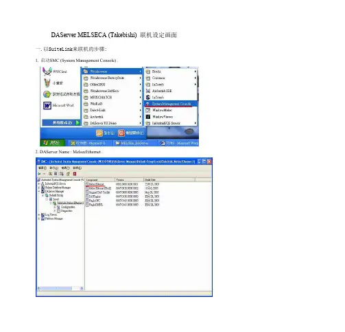
一.以SuiteLink来联机的步骤:
1. 启动SMC (System Management Console) .
2. DAServer Name : MelsecEthernet .
3. 将PokБайду номын сангаас Mode 选成: Control Mode .
12. 关闭关闭关闭关闭MelsecEthernet ,于Takebishi.MelsecEthernet.1上按下鼠标右键,选到
Deactivate Server 就可以关闭Daserver .
整体架构如下图整体架构 如下图整体架构如下图整 体架构如下图:
二.以IAS OPC Client来联机的步骤:
Browse OPC ItemBrowse OPC I点t击em这Br个ow按se钮OP,C 会It出em现Br一ow个se浏览OPC服务器的对话框, O通P过C 拖It拽em操作可以进行标签登录。
选中拖入的标签,然后点击下方的
,出现一个
在Itemname中默认,不要填写任何就可以,直接点ok,添加完成后,回到前面,点击device items中就会出现选择好的标签名, 然后双击选中一个名字,复制,在下面的与intouch链接中需要用到
Intouch7.11 DDE接口: 支持远程DDE通讯,运行DDEShare.exe定义DDE共享项(假设Share), 关键性参数[大小写不敏感]: APPLICATION名: View TOPIC名: Tagname 本机方式访问位号的命令路径就是:View|Tagname!位号; 远程访问步骤如下: 1> 使客/服之间的用户名、密码与工作组名分别相同; 5> 运行ddeshare.exe,设置dde共享项Share及Application与Topic参数,并建立信任关
INTOUCH和PLC连接

双击L1灯,在弹出的动画组态属性设置对话框,在“特殊动画连接”
栏中的”可见度”复选框,这时将出现“可见度”选项卡,单击它将出
现如图22的可见度动画设置对话框.
2021/12/26
2021/12/26
30
图21 动画组态(zǔ tài)属性设置
对话框
精品PPT
在表达式文本框中输入“L1”,或单击右边带“?”的方块在弹出的数据
属性设备对话框,如图11
2021/12/26
2021/12/26
17
精品PPT
图11 PLC通道属性(shǔxìng)设
备对话框
此时所建立的I0.0已出现在PLC通道(tōngdào)属性设备对话框
中,依此类推可建立其他的通道(tōngdào),单击”确认”按钮回
到设备属性设置对话框,在设备属性设置对话框单击”通道
就非常简单,只需要在欲设置动画的构件的动画组态属性设置对话框
中选中相应的动画连接复选框,然后将对应的数据对象与之连接起来
就行了.
比如说PLC系统中有一个指示灯,它是由I0.0控制的,如果我们要监
视它的状态该哪么来做呢?
首先我们肯定要在监控界面中画一个指示灯构件,然后双击它,这
时会出现如图13所示的“动画组态”属性设置
2021/12/26
2021/12/26
20
精品PPT
对话框”,选中其中的“可见度”复选框,然后单击
”可见度”选项卡,动画组态属性设置对话框转
为可见度动画设置,如图14在表达式文本框中
输入(shūrù)所需的表达式,或单击右边的
2021/12/26
2021/12/26
图13 动画组态属性(shǔxìn021/12/26
如何配置Intouch SIDirect DAServer 通过TCP_IP和S7 PLC通信
如何配置Intouch SIDirect DAServer 通过TCP/IP和S7 PLC通信如何配置SIDirect DAServer 通过TCP/IP实现和S7 PLC的通信概要介绍无需借助西门子的Simaticnet 软件,SIDirect DAS Server 可以通过标准的以太网卡访问S7 200, S7 300,S7 400 家族PLC。
SIDirect DAServer可以通过DDE, FastDDE, SuiteLink, OPC协议连接Windows客户端软件,如Wonderware InTouch。
本Tech Note 一步一步详细介绍了如何配置和使用Wonderware SIDirect DA Server连接/访问S7 PLC(这里,我们以S7-400 PLC 为例),以及如何用DDE/SuiteLink协议访问此DA Server。
在开始之前,请确保已满足以下条件:1.仔细阅读并按照SIDirect DAServer的Readme文件及相关文档,来得到SIDirect DAServer所需要的系统需求,正确的安装过程,操作系统等信息。
2.安装SIDirect DAServer,如果已经安装了以前版本的SIDirect DAServer,请使用的"控制面板"中的"添加/删除程序"卸载,本Tech Note使用SIDirect DAServer 1.1版。
3.安装并配置以太网卡和TCP/IP协议。
4.确认你可以"Ping"通你要连接的PLC。
注意:请仔细阅读SIDirect DAServer的在线文档关于所支持的硬件和软件部分,SIDirect DAServer只支持TCP/IP 通信,不支持MPI,Profibus等其他非以太网方式。
本Tech Note假定用户具有并理解以太网,西门子S7 PLC 硬件/软件,Windows 操作系统,Wonderware FactorySuite组件,WWClinet, SIDirect DAServer的基本知识。
如何配置Intouch SIDirect DAServer 通过TCPIP和S7 PLC通信
如何配置Intouch SIDirect DAServer 通过TCP/IP和S7 PLC通信如何配置SIDirect DAServer 通过TCP/IP实现和S7 PLC的通信概要介绍无需借助西门子的Simaticnet 软件,SIDirect DAS Server 可以通过标准的以太网卡访问S7 200, S7 300,S7 400 家族PLC。
SIDirect DAServer可以通过DDE, FastDDE, SuiteLink, OPC协议连接Windows客户端软件,如Wonderware InTouch。
本Tech Note 一步一步详细介绍了如何配置和使用Wonderware SIDirect DA Server连接/访问S7 PLC(这里,我们以S7-400 PLC 为例),以及如何用DDE/SuiteLink协议访问此DA Server。
在开始之前,请确保已满足以下条件:1.仔细阅读并按照SIDirect DAServer的Readme文件及相关文档,来得到SIDirect DAServer所需要的系统需求,正确的安装过程,操作系统等信息。
2.安装SIDirect DAServer,如果已经安装了以前版本的SIDirect DAServer,请使用的"控制面板"中的"添加/删除程序"卸载,本Tech Note使用SIDirect DAServer 1.1版。
3.安装并配置以太网卡和TCP/IP协议。
4.确认你可以"Ping"通你要连接的PLC。
注意:请仔细阅读SIDirect DAServer的在线文档关于所支持的硬件和软件部分,SIDirect DAServer只支持TCP/IP 通信,不支持MPI,Profibus等其他非以太网方式。
本Tech Note假定用户具有并理解以太网,西门子S7 PLC 硬件/软件,Windows 操作系统,Wonderware FactorySuite组件,WWClinet, SIDirect DAServer的基本知识。
Intouch与西门子S7-200S7--300S7--400的以太网通讯配置

I n t o u c h与西门子S7-200/S7-300/S7-400的以太网通讯配置无需借助西门子的Simaticnet 软件,SIDirect DAS Server 可以通过标准的以太网卡访问S7 200, S7 300,S7 400 家族PLC。
SIDirect DAServer可以通过DDE, FastDDE, SuiteLink, OPC协议连接Windows客户端软件,如Wonderware InTouch。
注意:SIDirect DAServer只支持TCP/IP通信,不支持MPI,Profibus等其他非以太网方式。
这里以Intouch2014与西门子400的以太网冗余通讯为例,所需软件如下:Intouch2014要求采用SIDirect 3.0sp1版本的驱动,Intouch10.0/10.1等采用更低版本如1.5/2.0等。
配置SIDirect DAServer 步骤如下:1、开始菜单——所有程序——Wonderware——System Management Console,双击启动System Management Console程序;2、在ArchestrA System Management Console(SMC)中找到“DAServer Manager”,依次展开Default Group——Local——ArchestrA.DASSIDirect.33、展开ArchestrA.DASSIDirect.3,并选择“Configuration”,将出现如下“Global Parameters”对话框:【参数一般默认不修改】◆Device Group Update Interval: 定义Device Group的默认更新时间间隔◆Slow Poll Interval: 定义当连接发生问题进入“Slow Poll”模式时,DAServer查询设备的时间间隔。
当通信恢复正常后,DAServer的查询间隔调整为Device Group的查询间隔。
驱动_AVEVA INTOUCH和西门子S7200SmartPLC通讯设置
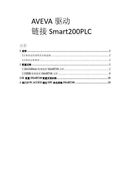
AVEVA驱动链接Smart200PLC目录1 说明 (2)1.1驱动支持说明及安装选择 (2)1.2驱动安装事项 (2)2 配置过程 (2)2.1DASSIDirect配置链接SMART200过程 (2)2.2SIDIR配置链接SMART200过程 (6)3 OI 配置SMART200配置页面示例 (10)4 西门子PC ACCESS通过OPC协议采集SMART200 (10)1说明组态软件从现场PLC读取数据,均需要经过驱动程序,本说明文档为配置A VEV A(原Wonderware)驱动,读取西门子SMART200PLC数据,本次使用使用CPU型号为SIEMENS 200SMART SR30。
1.1驱动支持说明及安装选择A VEV A(原Wonderware)驱动有DA和OI两种类型的驱动,两种驱动在数据采集逻辑配置本质上无较大区别,由于DA在面对单台计算机采集大批量点位的环境会面临着硬件、软件服务承载能力以及内存分配等限制,OI版本驱动对此做了优化,可以多实例来分别去采集,从架构层面来解决大型项目现场单台服务器的数据采集问题,DA驱动后续不再继续更新,OI驱动将保持持续更新,包括兼容新版本操作系统、以及新型号硬件。
因此在新项目种建议使用OI驱动,而不是DA。
DA西门子驱动DASSIDirect,支持带以太网模块的200、200SMART、300、400,3.0SP1版本驱动支持1200、1500较老固件版本的数采,某些固件版本需要配置博图。
OI西门子驱动SIDIR,支持带以太网模块的300、400、1200、1500,支持1200、1500的Symbol地址,支持平台种AutoBuild符号化模板。
由于OI驱动官方并不显示支持SMART200型号PLC,但当前此PLC依然在市面上非常常见,特别是小型项目上。
因此此文档用于说明该型号的链接方式。
注:OI驱动多实例采集功能需要使用专业版或高级版采集驱动,标准版不支持多实例。
S7-200与Intouch通讯
通过Daserver配置S7-200与Intouch的通讯一.PLC程序中,配置CP243网卡参数
1.PLC程序中,向导 以太网,如下图所示:
PLC会自动搜索CP243网卡,并显示出其在组态中所占据的槽位,槽位定义从0开始,且CPU不占槽位。
注意:由于Daserver中默认将CP243网卡槽位定义为0,所以需要网卡要保持和CPU间的直接相连,中间不得有任何其他的模块。
2. 设定网卡地址,使PLC与上位机保持在同一网络路径下:
3. 设定需要和CP243进行通讯连接数目,最多支持8个通讯连接站点:
4.数据传输站点及参数配置:选择服务器连接模式,可以选择接受所有连接或指定IP address的连接。
本地属性(PLC):TSAP:“10.01”,“01”指CP243所在的槽位,最好是保持在00位,即CP243直接插在CPU后面。
远程属性(上位机):TSAP:“10.03”,请记录并与后续DAserver中保持一致。
5.完成向导配置,并download至CPU中。
二DaServer配置
1.安装DAServer DASSIDirect驱动程序,添加port CpS7 :
2. 添加New_S7_CP200_000,指定将要连接的模块IP address,并配置相应的Local TASP & Remote TASP属性,并添加出相应的Device Group Or Device Items,即可完成设定。
Local指上位机,Remote指PLC。
注意和PLC中CP243设定相对应。
Intouch 怎样用DASSIDirect with Siemens S7-200 PLC 通讯
Configure the S7-200 PLC1.Start Step7-Micro/Win 32. Create a new project or load your existing one(Figure 1 below):F IGURE 1:S TEP 7-M ICRO/WIN32-P ROJECT1D IALOG B OX2.Click on Tools and then select Ethernet Wizard.3.Step through the wizard:F IGURE 2:E THERNET W IZARD4.Click Yes when asked to use symbolic addressing. Otherwise the wizardcannot continue:F IGURE 3:C LICK Y ES5.Enter the module position of the CP243-1.If you are uncertain about the position, click the button Read Modules.Otherwise you can enter the number directly:F IGURE 4:S PECIFY M ODULE P OSITION D IALOG B OX6.Enter the IP configuration of your CP243-1.Especially during the startup phase of the project, I would recommend not to use a BOOTP server.Let the module detect the connection type (Figure 5 below):F IGURE 5:M ODULE A DDRESS C ONFIGURATION7.Enter the numbers of connections you want to configure for the CP243-1.Default value is 0, which would not allow communication. In this exampleI will use 2 connections (Figure 6 below):F IGURE 6:2C ONNECTIONSNow you have to configure the connections. Connection 0 (Figure 7below) will accept all incoming client requests:F IGURE 7:C ONNECTION C ONFIGURATION8.Always select This is a Server Connection. I recommend using thedefault TSAP's as suggested by Step7-Micro/Win32.9.Click Next Connection (or Prev. Connection if available) to stepthrough all the connections to configure them.Note: If you plan to use such a connection, be sure that only one client tries to connect to the PLC via this connection at the same time. All other connection tries will be rejected.Connection 1 accepts only requests from the specified client:F IGURE 8:S PECIFIED C LIENT R EQUESTS10.If all connections are configured click OK.During the startup phase of a project I would recommend not to use a CRC protection:F IGURE 9:N O CRC P ROTECTIONThe wizard now needs a range in the V-Memory where to store thisinformation. Step7-Micro/Win32 will suggest a valid range.11.Click on Suggest Address if you have planned to use this range forsomething else.In this case Step7-Micro/Win32 will suggest another free range that has the correct size to hold this data:F IGURE 10:S TORE M EMORY A LLOCATION FOR A DDRESS12.Click Next.The program now has enough information:F IGURE 11:G ENERATE P ROJECT C OMPONENTS13.Click Finish to complete the configuration:F IGURE 12:C OMPLETE THE W IZARD C ONFIGURATION14.Click Yes.In Step7-Micro/Win32 you should now see something like thefollowing figure:F IGURE 13:S TEP7_M ICRO/W IN32W INDOWStep7-Micro/Win32 has created some new entries in the V-Memory, starting at the address as specified during the setup of the CP243-1.15.Download the configuration to the PLC:F IGURE 14:D OWNLOAD THE C ONFIGURATION16.Select all options and click OK (Figure 15 below):F IGURE 15:D OWNLOAD O PTIONS17.Set the PLC to STOP mode in order to be able to download a newconfiguration:F IGURE 16:PLC STOP M ODE18.After the download don't forget to set the PLC to RUN mode again. Thiswill not be done automatically:F IGURE 17:PLC RUN M ODEThe PLC side is now configured.Configure the DAServerConfiguration of the DAServer is quite easy.Since we have created two connections in the PLC, we will also create two connections in DASSIDirect DAServer.Connection 0 will correspond to the connection asF IGURE 18:DASSID IRECT C ONNECTION 0The Remote TSAP in DASSIDirect must be the Local TSAP in the PLC configuration, and vice versa.Connection 1 shown in Figure 19 (below) will correspond to the connection as created inF IGURE 19:DASSID IRECT C ONNECTION 1Now create your device group(s), if necessary.For a DDE/SuiteLink connection you need to have at least one device group per connection, for OPC it is not necessary. For to test the communication as described below, please enter a device group called S7200.The connection between DASSIDirect and the S7-200 PLC should now be ready to test. Test the CommunicationIn previous TechNotes we used wwclient for testing. This tool will no longer be installed when installing ArchestrA (A²) products like InTouch 8.0 or any DAServer. If you have InTouch 7.11 installed you will find this tool under Program Files/Wonderware FactorySuite/Common and you can use this tool.1.Create a simple InTouch application with one tag.2.Select Special/Access Names from the main menu.3.Select Add.The Add Access Name dialog box appears:F IGURE 21:A DD A CCESS N AME4.Enter a meaningful name in the Access field.5.Leave the Node Name blank if you have InTouch and DASSIDirect onthe same node.Otherwise enter the nodename of the PC where DASSIDirect resides.The Topic Name must match the Device Group name as configured in DASSIDirect.6.Select Special/Tagname Dictionary and select New.F IGURE 22:N EW T AGNAME7.Select Type: I/O Integer and the access name as created in theprevious steps.e the item MB1 because it always exists in all S7-200 PLCs.Use this tag in the window you just created.9.Activate DASSIDirect in the System Management Console (SMC).10.Start WindowViewer™.11.Open the Diagnostic in the SMC to verify the communication:F IGURE 23:C HECK C OMMUNICATION FROM THE SMCIf you see a Time value that is changing, and a Client Quality of 00C0, your communication is fine.。
Intouc与S7200、昆腾通讯PLC
Intouch与S7-200通过FSGateway实现通讯(PPI方式)1、首先配置S7-200,建立OPC服务器:A、这里需要安装PC Access套件,双击打开桌面上”V1.0 PC Access SP3”:B、配置一个PC Access文件,作为OPC服务器:这里的” MicroWin.S7PLC.GG”即为后来intouch里的变量名。
2、服务器配好的,配置FSGateway:以下介绍使用Wonderware公司的SCADA软件(FactorySuite Gateway)与S7-200OPC服务器时的关于SCADA设定的方法。
FS Gateway作为替OPCLink的新一代网管软件2004年开始销售。
它是将4种协议(OPC/DDE/SuiteLink/MX)进行相互变换的通用协议转换器软件。
安装FS Gateway从Wonderware公司网页中下载FS Geteway的安装软件(ZIP文件)。
将ZIP文件解冻并进行安装。
启动FS Gateway从开始菜单的[程序]中的点击[Wonderware],在点击[System Management Console],启动SMC。
打开DA服务器管理器后会看到[ArchestrA.FSGateway]。
定义OPC服务器右击[Configuration],会出现弹出式菜单,请选择其中的[Add OPC Object]。
服务器Node指定OPC服务器运作中的节点名称。
在同一台PC上使用时,指定为[localhost]。
服务器名称指定OPC服务器的Prog.ID。
S7200的OPC Server的Prog.ID为[S7200.OPCServer]。
# 不需要变更其他的设定。
定义OPC的组右击上述OPC服务器的定义(如果为图像表示时,[New_OPC_000]),会出现弹出式菜单,选择其中的[Add OPCGroup Object]。
Update Rate指定PLC的polling周期。
intouch通过opc-link与s7200通讯
Intouch通过OPCLink与s7-200通讯
配置一共四步:
一,Micro/WIN配置以太网向导(即以太网模块CP243-1的配置);
二,PC-Access的配置;
三,OPC-Link的配置(wonderware的I/Oserver中);
四,上位机Intouch的配置。
一以太网模块CP243-1的配置
1.1 Micro/WIN以太网向导配置;
注:若勾选接受所有连接请求,即可实现多个用户对模块CP243-1的通讯
完成以太网向导配置;
1.2:在mirco/win添加程序(完成初始化);
1.3,编写下位机程序,编译(compile),下载程序
二PC-ACCESS的配置;
PC-Access总体分三步:
1建立项目;2建立PLC连接;3使用客户测试机;
2.1建立PLC连接
2.2建立PLC连接
(对应自己电脑的网卡)
2.3使用客户机测试;
(选中自己的项目,拖拽至测试客户机)
三OPC-LINK的配置;
四intouch的配置
4.1 设置访问名
(访问名与主题名必须一模一样的),
4.2 标记名字典。
- 1、下载文档前请自行甄别文档内容的完整性,平台不提供额外的编辑、内容补充、找答案等附加服务。
- 2、"仅部分预览"的文档,不可在线预览部分如存在完整性等问题,可反馈申请退款(可完整预览的文档不适用该条件!)。
- 3、如文档侵犯您的权益,请联系客服反馈,我们会尽快为您处理(人工客服工作时间:9:00-18:30)。
通过Daserver配置S7-200与Intouch的通讯一.PLC程序中,配置CP243网卡参数
1.PLC程序中,向导 以太网,如下图所示:
PLC会自动搜索CP243网卡,并显示出其在组态中所占据的槽位,槽位定义从0开始,且CPU不占槽位。
注意:由于Daserver中默认将CP243网卡槽位定义为0,所以需要网卡要保持和CPU间的直接相连,中间不得有任何其他的模块。
2. 设定网卡地址,使PLC与上位机保持在同一网络路径下:
3. 设定需要和CP243进行通讯连接数目,最多支持8个通讯连接站点:
4.数据传输站点及参数配置:选择服务器连接模式,可以选择接受所有连接或指定IP address的连接。
本地属性(PLC):TSAP:“10.01”,“01”指CP243所在的槽位,最好是保持在00位,即CP243直接插在CPU后面。
远程属性(上位机):TSAP:“10.03”,请记录并与后续DAserver中保持一致。
5.完成向导配置,并download至CPU中。
二DaServer配置
1.安装DAServerDASSIDirect驱动程序,添加port CpS7:
2. 添加New_S7_CP200_000,指定将要连接的模块IP address,并配置相应的Local TASP & Remote TASP属性,并添加出相应的Device Group Or Device Items,即可完成设定。
Local指上位机,Remote指PLC。
注意和PLC中CP243设定相对应。