低TCR超低阻值贴片电阻规格书(选型手册)
贴片电阻规格书
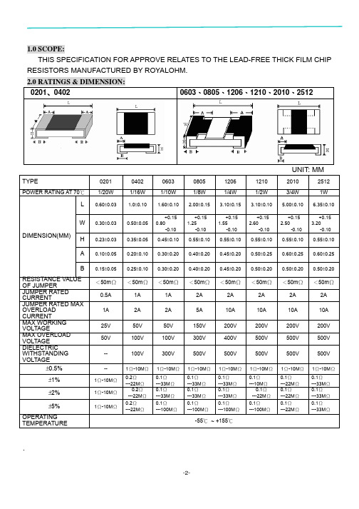
5.1 VOLTAGE RATING: RESISTORS SHALL HAVE A RATED DIRECT-CURRENT (DC) CONTINUOUS WORKING VOLTAGE OR AN APPROXIMATE SINE-WAVE ROOT-MEAN-SQUARE (RMS) ALTERNATING-CURRENT (AC) CONTINUOUS WORKING VOLTAGE AT COMMERCIAL-LINE FREQUENCY AND WAVEFORM CORRESPONDING TO THE POWER RATING, AS DETERMINED FROM THE FOLLOWING FORMULA:
34
392
58
698
82
127
11
226
35
402
59
715
83
130
12
232
36
412
60
732
84
133
13
237
37
422
61
750
85
137
14
243
38
432
62
768
86
140
15
249
39
442
63
787
87
143
16
255
40
45364ຫໍສະໝຸດ 80688147
17
261
41
464
65
825
EXAMPLE:
33000 → 33KΩ
(3) ±2%、±5%TOLERANCE: BELOW 10Ω SHOW AS FOLLOWING, READ ALPHABET”R” AS DECIMAL POINT. EXAMPLE:
超低阻(合金)贴片电阻-LR

超低阻(合金)贴片电阻-LR 系列-高功率可达3W-低温漂±50, ±100 PPM/℃-阻值从0.5到20 m ohms-低感抗,未经激光切制-可以依据客户要求制作-NB (-MB (--监视器(c产品类型产品类型LR 超低阻合计贴片电阻d Dimensions (L×W)代号Dimensions (L×W) EIALR12 6.3×3.1mm2512e Resistance Tolerance代号阻值公差J ±5%H ±3%G ±2%F ±1%f Packaging代号类别T TapingReelg TCR代号类别D ±50 PPM/℃W ±75 PPM/℃E ±100 PPM/℃K ±150 PPM/℃R003h Power Rating代号类别Standard (1W)S (2W)R (3W)B (2.5W)i阻值代号类别0M50 0.00050Ω0M75 0.00075Ω1M50 0.00150ΩR002 0.00200ΩR020 0.02000Ωj Protective Coating代号类别BlackCoatingG GreenCoatingOperating Current I=√(P/R):Operating Voltage V=√(P*R) 高功率电器特性Operating Current I=√(P/R),Operating Voltage V=√(P*R) * Viking 能够根据客户要求制作一下选项。
凸层塑料带说明Top Tape1 1.4Min.Unit: mm阻值 (m Ω)ABW E F P 0P 1P 2ΦD 0T 0.50 3.40±0.1 6.70±0.112.0±0.1 1.75±0.1 5.5±0.05 4.0±0.05 4.00±0.1 2.0±0.05 1.50+0.1 1.40±0.10.75 3.50±0.1 6.80±0.212.0±0.1 1.75±0.1 5.5±0.05 4.0±0.05 4.00±0.1 2.0±0.05 1.50+0.1 1.35±0.11~203.40±0.1 6.70±0.112.0±0.1 1.75±0.15.5±0.054.0±0.054.00±0.12.0±0.05 1.50+0.10.80±0.1注意:1. 10个齿轮的倾斜积累公差是 ±0.2mm.2. 通过250mm 的凸形带时,每100mm 不高出1mm3. A 和 B 测量是从带底端0.3mm 处开始测量4. t 尺寸的测量是从凸形带的顶端到底端某一点的测量距离。
电阻参数

100K 110K 120K 130K 150K 160K 180K 200K 220K 240K 270K 300K 330K 360K 390K 430K 470K 510K 560K 620K 680K 750K 820K 910K
1.0M 1.1M 1.2M 1.3M 1.5M 1.6M 1.8M 2.0M 2.2M 2.4M 2.7M 3.0M 3.3M 3.6M 3.9M 4.3M 4.7M 5.1M 5.6M 6.2M 6.8M 7.5M 8.2M 9.1M
贴片电阻标准阻值
常规的贴片电阻阻值采用 E24,E96 系列。 1948 年 IEC 第 12 技术委员会(无线电通讯)在斯德哥尔摩会议讨论过程中,一致同意国际标 准化最紧迫的课题之一就是电阻器和 0.1uF 以下电容器的优先数系列。
尽管想使这些系列按照 10 10 数系标准化,但在若干国家内由于上述元件针对 5 10 、 10 10 和
图 2 (-55 ~+155)功率及环境温度降额曲线图 注意事项 :
• 设计和使用贴片电阻时,最大功率不能超过其额定功率,否则会降低其可靠性。 • 一般按额定功率的 70%降额设计使用。 • 也不能超过其最大工作电压,否则有击穿的危险。 • 一般按最高工作电压的 75%降额设计使用。 当环境温度超过 70°C,必须按照降额曲线图(图 1,图 2)降额使用。
1210 3225 3.20±0.20 2.50±0.20 0.55±0.10 0.50±0.20 0.50±0.20
1812 4832 4.50±0.20 3.20±0.20 0.55±0.10 0.50±0.20 0.50±0.20
2010 5025 5.00±0.20 2.50±0.20 0.55±0.10 0.60±0.20 0.60±0.20
通用型贴片电容规格书(选型手册)

【 南京南山半导体有限公司 — 贴片电容选型资料】MULTILAYER CHIP CERAMIC CAPACITORCOG/COHCOG, ,-55125,030ppm/060ppm/0805CG101J500NT(PF) ( 0402 0.04 0603 0.06 0805 0.08 1206 0.12 ) 0.02 0.03 0.05 0.06 1.00 1.60 2.00 3.20 ( ) 0.50 0.80 1.25 1.60 CG CH COG NPO COH 100 101 102 10 100 1J G C B D5.00% 2.00% 0.25PF 0.10PF 0.50PF10 10 10 1026R3 100 250 5006.3V 10V 25V 50VS C N / / T BWBWTL mm L 0402 0603 0805 1206 1005 1608 2012 3216 1.00 1.60 2.00 3.20 0.05 0.10 0.20 0.30 W 0.50 0.80 1.25 1.60 0.05 0.50 0.10 0.80 0.20 0.80 1.00 1.25 0.20 0.80 1.00 1.25 T WB 0.05 0.25 0.10 0.30 0.20 0.50 0.20 0.20 0.20 0.60 0.20 0.20 0.10 0.10 0.20 0.3015【 南京南山半导体有限公司 — 贴片电容选型资料】0.80 0.20 1.00 0.20 0.50 0.80 0.20 1.00 0.20 0.600.20 0.30【 南京南山半导体有限公司 — 贴片电容选型资料】MULTILAYER CHIP CERAMIC CAPACITORCOG/COH 0402 0603 0805 12066.3V 10V 16V 25V 50V 6.3V 10V 16V 25V 50V 6.3V 10V 16V 25V 50V 6.3V 10V 16V 25V 50V0.5PF 1PF 2PF 3PF 4PF 5PF 6PF 7PF 10PF 22PF 33PF 47PF 68PF 100PF 120PF 150PF 180PF 220PF 330PF 470PF 560PF 680PF 1000PF 2200PF 2700PF 3300PF 4700PF 5600PF 6800PF 10nF 12nF 15nF 22nF 47nF 68nF 100nF17【 南京南山半导体有限公司 — 贴片电容选型资料】04020603080512066.3V 10V 16V 25V 50V 6.3V 10V 16V 25V 50V 6.3V 10V 16V 25V 50V 6.3V 10V 16V 25V 50VCapacitance0.5PF 1PF 2PF 3PF 4PF 5PF 6PF 7PF 10PF 22PF 33PF 47PF 68PF 100PF 120PF 150PF 180PF 220PF 330PF 470PF 560PF 680PF 1000PF 2200PF 2700PF 3300PF 4700PF 5600PF 6800PF 10nF 12nF 15nF 22nF 47nF 68nF 100nF【 南京南山半导体有限公司 — 贴片电容选型资料】MULTILAYER CHIP CERAMIC CAPACITORCOG COHPH~SLCOG PH SH SL TH RH UJCOH1-55125-55851. 2. 3. 2 4. 5. , , , , , 103 4 Cr 5PF 0.56% -4 5PF Cr 50PF 1.5 [(150/Cr)+7] 10 Cr 50PF 0.15% C C 10nF Ri 10nF Ri 5 10 Cr 500s 3 50mA 150+0/-10 8 25 9 75 235 5 2 0.5 25 60 265 10 1 25 : 1 2 100 170 120 200 1 1 2.5mm/ 24 2 5 5 5 2.5mm/ 245 24 -55 125 2 -55 85 60 510:HP4278A 1. 2. 3. (D.F.) :1.0 C : : (HP4284 25 5 0.2V 0.1MHz; 0.1KHZ ) 1000PF,1.0 :SF2511 , 60 60 1 5 :30% 75%5:C<1000PF,1.06I.R.7>3x150+0/-10 5% 0.5PF D.F. 10 I.R. 24 245【 南京南山半导体有限公司 — 贴片电容选型资料】General COGCOHPHSL MLCC reliability test methodStandard Number Item COG COH MLCC for General-use -55 125 PH, RH, SH, TH, UJ, SL MLCC for General-use -55 85 Check by using microscope 10 . Test Method1Operating Temperature RangeAppearance21.Good ceramic body color continuity. 2.The chips have no visual damages and must be very smooth. 3.No exposed inner- electrode, no cracks or holes. 4.The outer electrode should have no cracks, holes, damages or surface oxidation. 5.Outer electrode no prolongation or the prolongation is less than half of that of the termination width.3 4 5Dimensions Capacitance Dissipation Factor (DF)Within the specified dimensions Within the specified tolerance Cr 5PF 0.56% 5PF Cr 50PF 1.5 [(150/Cr)+7] 10-4 Cr 50PF 0.15% C C 10nF Ri 10nF Ri 5 1010 Cr 500sUsing micrometer or vernier calipers Measuring Equipments:HP4278 capacitance meter,HP4284 capacitance, Measuring Conditions: 1.Measuring Temperature:25 5 .Humidity: 30% 75%. 2.Measuring Voltage:1.0 0.2V. 3.Measuring Frequency:C<1000PF 1.0 0.1MHz C 1000PF 1.0 0.1KHz Measuring Equipment:Insulation resistance meter (such as Sf2511 insulation resistance). Measuring Method:Must measure at rated voltage, and measure the IR within 60 5 seconds. Must measure at 3 times rated voltage, dwell time: 60 1 seconds, no short and the changing/discharging current less than 50mA. First, pre-heat: heat treat 60 5 minutes at 150+0/-10 , then set it for 24 2 hours at room temperature. Measure the capacitance at -55 125 or -55 85 , the capacitance change ratio comparing to that of 25 must be within the specified range. Dip the capacitor into ethanol or colophony solution, and then dip it into 235 5 ( or 245 5 leadless eutedtic solder solution ) eutectic solder solution hanving lead for 2 0.5 seconds. Dipping speed: 25 2.5mm/second. First pre-heat: heat treat for 60 5 minutes at 150+0/-10 , then set it for 24 2 hours at room temperature. Then pre-heat the capacitance according to the following chart. Dip the capacitor into 265 5 eutectic solder solution for 10 1 seconds. Then set it for 24 2 hours at room temperature, then measure. Dipping speed: 25 2.5mm/second. Preheat conditions: Stage 1 2 Temperature 100 170 120 200 Time 1minute 1minute6Insulation Resistance7Withstanding Voltage Capacitance Temperature Characteristic>3x rated continuous working voltage Must meet the capacitor character temperature coefficient requirements within the operating temperature range. Tin coverage should be 75% of the outer electrode Appearance Cap. Change ratio DF No defects visible 5%or 0.5PF (whichever is larger)89SolderabilityResistance to Soldering10Same as original spec Same as original specIR46【 南京南山半导体有限公司 — 贴片电容选型资料】MULTILAYER CHIP CERAMIC CAPACITOR1 10N11 10N,10 1 :1.0mm/ 11.5mm 10 D.F. 12 55Hz 210 55Hz 10Hz 6 123 420 mm mmmm13mmmmmmmm150+0/-10 14 24 2 24 260 547【 南京南山半导体有限公司 — 贴片电容选型资料】NumberItems Adhesive Strength of TerminationStandard No removal of the terminations or other defect shall occurTest Method Solder the capacitor to the test jig (glass epoxy resin board) shown in Fig.1 using a eutectic solder.Then apply a 10N force inthe direction shown as the arrowhead.The aoldering shall be done either with an iron or using the reflow method and shall be conducted with care so that an iron or using the refow method and shall be conducted with care so that the soldering is uniform and free of defects such as heat shock,etc. 10N,10 1s Speed:1.0mm/s Glss epoxy resinboard11Fig.1 Vibration Resistance Appearance Capacitance No defects or abnormities Within the specified tolerance range Same as original spec12DFSolder the capacitor to the test jig (glass epoxy resin board). The capacitor should be subjected to a simple harmonic motion having a total amplitude of 1.5mm, the frequency being varied uniformly between the approximate limits of 10 and 55Hz, shall be traversed (from 10 Hz to 55 Hz then 10 Hz again) in approximately 1 minute.This motion shall be applied for a period of 2 hours in each 3 mutually perpendicular directions (total is 6 hours).Same i standarFif.2 Bending Resistance No cracks or other defects shall occur Solder the capacitor to the test jig (glass epoxy resin board) shown in Fig.3 using a eutectic solder. Then apply a 10N force in the direction shown as Fig.4. The soldering shall be done either with an iron or using the reflow method and shall be conducted with care so that the soldering is uniform and free of defects such as mm heat shock, etc.mm13mm mm mm14Temperature CycleAppearance No defects or abnormitiesPre-treatment: Heat-treat the capacitor for 60 5minutes at 150+0/-10 , then set it for 24 2 hours at room temperature. Perform five cycles according to the four heat treatments listed in the following table. Set it for 24 2 hours at room temperature, then measure.48mm【 南京南山半导体有限公司 — 贴片电容选型资料】MULTILAYER CHIP CERAMIC CAPACITOR2.5% 0.25PF, 1 10000M 2 3 4 2 3 30 3 2 3 30 3 2 314D.F. I.R.40 290 95 24 2500+24/-05% 0.5PF, 15 ( ) D.F. I.R. 10000M40 2 500+24/-0 5% 0.5PF, 16 D.F. I.R. 10000M90 95 24 22 50mA 5% 0.5PF, 17 D.F. I.R. 10000M1000 12 24 249【 南京南山半导体有限公司 — 贴片电容选型资料】NumberItem Temperature CycleStandard Cap. Change ratio D.F. I.R. 2.5% or 0.25 PF (whichever is larger) Same as original spec More than 10000M Heat-treatment:Test Method14stage temperature 1 lowest opeating temperature 3 2 normal temperature 3 high operating temperature 2 4 normal temperaturetime min. 30 3 2 3 30 3 2 3Humidity Steady StateAppearance Cap. Change ratio D.F. I.R.No defects or abnormities 5% or 0.5 PF (whichever is larger) Same as original spec More than 10000MSet the capacitor for 500+24/-0 hours at the condition of 40 2 and 90-95% humidity. Then remove and set it for 24 2 hours at room temperature, then measure.15Humidity LoadAppearance Cap. Change ratioNo defects or abnormities 5% or 0.5 PF (whichever is larger) Same as original spec More than 10000MApply rated voltage to the capacitor for 500+24/-0 hours at the condition of 40 2 and 90-95% humidity. Remove and set it for 24 2 hours at room temperature, then measure.16D.F. I.R.Life TestAppearance Cap. Change ratioNo defects or abnormities 5% or 0.5 PF (whichever is larger) Same as original spec More than 10000MApply two times rated voltage to the capacitor for 1000 12 hours at the upper temperature limits, the charging current should be less than 50mA. Remove and set it for 24 2 hours at room temperature, then measure.17D.F. I.R.5057-10%-5%0%5%10%COG 50VX7R 50V Z5U 50V Y5V50V010********-100%-80%-60%-40%-20%0%20%40%[Vdc]COG :1MHZ X7R,Z5U,Y5V:1KHZZ5U 50VY5V 50V X7R 50VC0G 50V0123-20%0%+20%+40%+60%^+80%COG PH RH SH TH UHCOG X7R Y5V,Z5U05010010001000010%0%-10%-20%-30%-40%[Hr]X7R20%0%[Vr ms ]COG :1MHZ X7R,Z5U,Y5V:1KHZMULTILAYER CHIP CERAMIC CAPACITOR58-5%0%5%10%-100%-80%-60%-40%-20%0%20%40%Z5U 50VY5V 50V X7R 50VC0G 50V0123-20%0%+20%+40%+60%^+80%COG X7R Y5V,Z5U05010010001000010%0%-10%-20%-30%-40%0%GENEREL-USE MLCC CHARCCTER PROFILESCapacitance change ratio DC Voltage[Vdc]Measuring condition COG :1MHzX7R,Z5U,Y5V:1KHzCOG and PHRH SH TH UH siriestemperature coefficentDC Capacitance-AC VoltageCharactericsCapacitance change_agingTime[Hr]X7R tempreture characteristicsZ5U [Vr ms ]Capacitance change ratioCapacitance change ratio Capacitance change ratio Capacitance change ratio。
超精密金属膜电阻军用标准(RE)规格书

D
50 0 -55 70 175 (°C) (RE)功率 - 温度曲线
型号 额定功率 (W) 最大工作电压(V) 尺寸(Unit: mm) 阻值范围(Ω) 工作溫度范围 标称阻值误差
70 °C L ± 0.3 D ± 0.4 A ± 0.05
RE50 0.125 200 4.0 1.4 0.40
1 ~ 3M
RE55 0.25 200 6.9 2.05 0.60
0.05 ~ 10M
RE60 0.5 250 9.8 3.2 0.60
0.05 ~ 10M
RE65 0.75 300 12.5 3.6 0.60
0.05 ~ 10M
RE70 1.0 350 14.1 4.65 0.80
0.05 ~ 10M
RE75 1.5 500 17.8 7.2 0.80
长期
无机械损伤,飞弧,绝缘击穿 短期
GJB244A (MIL-PRF-55182) 3.17/3.22/3.23 ΔR≤±(0.20%R+0.01Ω)
无机械损伤
GJB244A (MIL-PRF-55182)3.20 ΔR≤±(0.10%R+0.01Ω)
无机械损伤
Version 2014
德键电子工业股份有限公司
要求
GJB244A (MIL-PRF-55182) 3.24 ΔR≤±(0.5%R+0.01Ω) ΔR≤±(2%R+0.01Ω) GJB244A (MIL-PRF-55182)3.21 ΔR≤±(0.4%R+0.01Ω) GJB244A (MIL-PRF-55182)3.25 ΔR≤±(2.0%R+0.01Ω) GJB244A (MIL-PRF-55182) 3.18/3.29/3.16 ΔR≤±(0.15%R+0.01Ω)
PTC型号及选型指南
PTC型号及选型指南PRG系列陶瓷贴⽚⾃WMZ13A过流过压保WMZ12AⅠ过流保护WMZ12A Ⅱ过流过载智能电表线圈变压器通讯接⼝保护热敏电WMZ13A 汽车⽤过流LED灯具⾃恢复式过智能电表⽤⾃恢复式WMZ13B系列继电器阻PTC热敏电阻模块电容上电防浪涌冲击⾃恢复热敏电阻逆变焊机滤波电容上电浪涌抑制⾃恢复热敏电阻变频器储能电容浪涌抑制⾃恢复PTC热敏电阻逆变电源滤波电容上电浪涌抑制⾃恢复热敏电阻伺服驱动板滤波电容上电浪涌抑制⾃恢复热敏电阻WMZ12B 140V过流保护PTC热敏电阻WMZ12C 30V/60V 过流保护PTC热敏电阻WMZ12D 15V/18V 过流保护PTC热敏电阻600Vac通讯设备交换机过流过载保护PTC热敏电阻550Vac仪器/仪表/机过流过载保护PTC 热敏电阻250Vac配线架过流过载保护PTC热敏电阻WMZ7消磁PTC热敏电阻WMZ91裸⽚冰箱压缩机启动PTC热敏电阻壳装压缩机启动PTC热敏电阻250Vac配线架过流过载保护⾃恢复PTC热敏电阻通⽤PTC过热保护温度传感器KTY系列电机⽤温度传感器电机PTC热保护温度传感器贴⽚过热保护PTC热敏电阻测温型线性PTC热敏电阻插件过热保护PTC热敏电阻SMD贴⽚线性PTC热敏电阻NXP(恩智浦)KTY系列热敏电阻LED恒流补偿热敏电阻PTC热敏电阻器三⼤特性:BaTiO3陶瓷是⼀种典型的铁电材料,常温下其电阻率⼤于1012Ω.cm,相对介电常数⾼达104,是⼀种优良的陶瓷电容器材料。
在这种材料中引⼊稀⼟元素如Y、Nb等,可使其电阻率下降到10Ω.cm以下,成为具有很⼤的正温度系数的半导体陶瓷材料,在居⾥温度以上⼏⼗度的温度范围内,其电阻率可增⼤4-10个数量级,产⽣PTC效应。
这种效应是⼀种晶界效应,只有多晶陶瓷材料才具有。
正是由于这种PTC效应,PTC热敏电阻器得到了极其⼴泛的应⽤。
根据应⽤领域划分,PTC热敏电阻器有三⼤特性:电阻-温度特性;伏安特性;电流时间特性。
贴片电阻最新规格书(无铅)

第 2 页 共 24 页
风华高科 FENGHUA
广东风华高新科技股份有限公司
G U A N D O N G F E N G H U A A D VA N C E D T E C H N O L O G Y ( H O L D I N G ) C O . , LT D
常规片式电阻器承认书 Approval sheet for general chip resistor
电阻值代号
Resistance Value Code
三位数 E-24 系列 前两位表示
有效数字 第三位表示有效数
字 后 零 的 个 数 Three digits
(E-24 series): The first two
digits are significant figures
and the third one denotes
2010 2512, and the features are as below:
*体积小 重量轻
miniature and light weight
*电性能稳定 可靠性高
stable electrical capability and high reliability
*机械强度高 高频特性优越
superior mechanical and frequency
提升功率系列
S
Upgraded Power
Series
0603 K 0805 1206 1210 L 1812 2010 2512 M
跨接电阻 chip jumper
100ppm/
250ppm/
500ppm/ 无表示 no marking
版本号 version of:R-5.3 DH05-0318
产品规格书火炬-贴片排阻RCA规格书TH019-A-07
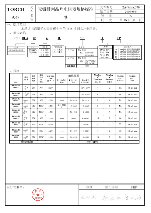
文文件编号QA-WI-K079 件 制订日期 2004-6-9 名 版 次 A TOR C H 火炬 称 无铅排列晶片电阻规格标准 书页 次 共16页 第3页 四、尺寸:( )R C A02-2D/RTA03-2D/RTA03-2C R C A02-4D/RCA03-4DR C A02-4C/RTA03-4CR C A02-8D/RTA03-8CCircuits Circuits2 Circuits L 1 L 1称 页 次 共16页 第7页Specifications 规格 TEM项目Conditions 条件 Resistors Jumper◎测试方法三(电烙铁试验):加热温度:350±10℃电烙铁加热时间:3+1/-0sec.取电铬铁加热于电极两端后,取出静置60分钟以上,再量测阻值变化率。
依据SONY (SS-00254-5)依据JIS-C5202-6.10步骤 制程名称 试验环境条件1 阻值量测 室温2 烘干 125℃、24小时3 湿润 85℃、85%RH 、168小时4 焊锡炉测试260±3℃、10秒 5 静置 室温6 焊锡炉测试260±3℃、10秒 7 阻值量测 室温Solderability 焊锡性 前处理将晶片电阻放置于PCT 试验机内,在温度105℃、湿度100%及气压1.22×10⁵ pa 的饱和条件下进行4小时的老化测试,取出后静置于室温下2小时。
测试方法◎测试项目一(焊锡炉测试):将电阻浸于245±3℃之炉中3+1/-0秒后取出置于显微镜下观察焊锡面积。
◎测试项目二(小球平衡法):将浸渍助焊剂后的电阻置放于Wetting Balance 测试机,依下列条件做设定,并记录晶片电阻焊锡润湿时间。
焊锡槽平衡法测试条件条件焊锡温度 245±3℃浸渍速度 1~5mm/S浸渍高度 0.10mm浸渍角度 水平25mg →0402、0603 锡球重量 200mg →0805、1206、1210、2010、2512依据SONY (SS-00254-2)依据JIS-C5202-6.111.试验项目一: 导体吃锡面积应大于95%。