LA5220P2450-A04--BLE陶瓷天线
PA24500-24GHz 无线信号放大器

PA24500-2.4GHz 无线信号放大器
产品介绍 PA24500-2.4GH Nhomakorabea 无线信号放大器是一个 高效率紧凑部件。为所有的 2. 4GHz 频段 无线设备增加性能和覆盖范围而设计。包 括蓝牙,P2P,P2MP,802.11b,802.11b+, 802.11g 和 802.11n 无线路由器, AP,无 线网卡。使用此产品在可视距离范围内可 将无线信号覆盖范围增加到双倍以上。能 有效解决无线网络信号弱和无线电波干扰 的问题。搭配高增益天线效果更佳。 产品技术规格详述 模块名称 频率范围 信号类型 毛重 盒子尺寸〔长宽厚〕 连接头类型 连接头阻抗 最大输出功率 安装步骤 PA24500 2.4 – 2.5 GHz DSSS ≈300 克 23*14.5*4 CM RP-SMA /RP-TNC 50 欧姆 2000 毫瓦/+33dbm 电源适配器 工作温度 指示灯 典型输入输出增益 最大接收输入功率 最大发射输入功率 ≥18db -30 dbm +15 dbm 电源:绿色 发射:红色 接收:橙色 6 V,2A
安全法规
·室内干燥环境使用 ·接室外天线请配避雷器 ·请保证散热环境良好 ·未接天线时请勿插电源
<
适用范围 无线网络热点 无线局域网络 远距离桥接 产品特性 用于无线 AP ,Wi-Fi 无线路由器 增加信号作用距离,增加信号穿透力 安装快速简便 兼容协议 WLAN 802.11b , 802.11b+ , 802.11g , 802.11n ,ISM 波段 ,蓝牙
80℃
包装附件
·放大器 1 只 ·2.15 dbi 全向天线 1 只 ·RP-SMA 转 RP-TNC 接头 1 只 ·6V 2A 直流电源 1 只
双模蓝牙CC2564模块集成抗干扰天线评估板快速入门指南(December 2015)说明书

Quick Start GuideSWRU425–December2015 Dual-Mode Bluetooth®CC2564Module With IntegratedAntenna Evaluation BoardThis quick-start guide offers an overview of the CC2564MODAEM evaluation board for the dual-mode Bluetooth CC2564module with integrated antenna(CC2564MODA),including required hardware and software tools and basic settings.For more information,see the Dual-Mode Bluetooth CC2564Module With Integrated Antenna Evaluation Board User Guide(SWRU427).Contents1Introduction (2)2CC2564MODAEM Kit Contents (2)3CC2564MODAEM Requirements (3)4CC2564MODAEM Board Overview (4)5CC2564MODAEM Board Settings (5)List of Figures1CC2564MODAEM Board (2)2Hardware Setup Examples (3)3CC2564MODAEM Front View (4)4CC2564MODAEM Back View (4)List of Tables1EM1Standard Pinout (5)2EM2Standard Pinout (5)3COM Connector Pinout (6)1 SWRU425–December2015Dual-Mode Bluetooth®CC2564Module With Integrated Antenna EvaluationBoard Submit Documentation FeedbackCopyright©2015,Texas Instruments IncorporatedIntroduction 1IntroductionThe CC2564MODAEM board is used to evaluate the TI CC2564MODA device,which supports classicBluetooth and Bluetooth low energy(LE)wireless technology.The CC2564MODAEM works with TI'shardware development kits(HDKs),such as the following:•MSP-EXP430F5529•MSP-EXP430F5438•DK-TM4C123G•DK-TM4C129XThe CC2564MODA device is a complete basic rate(BR),enhanced data rate(EDR),and LE hostcontroller interface(HCI)solution that reduces design effort and enables fast time to market.Based on TI’s seventh-generation core,the module brings a product-proven solution supporting Bluetooth4.1dual-mode protocols.Figure1shows the CC2564MODAEM board.2564MODAEM Board2CC2564MODAEM Kit ContentsThe CC2564MODAEM kit contains the following contents:•One CC2564MODAEM board,including the dual-mode Bluetooth CC2564module with integrated antenna•One block jumper for the MSP-EXP430F5438board•Four jumpers for the MSP-EXP430F5529board2Dual-Mode Bluetooth®CC2564Module With Integrated Antenna Evaluation SWRU425–December2015 Board Submit Documentation FeedbackCopyright©2015,Texas Instruments Incorporated CC2564MODAEM Requirements 3CC2564MODAEM RequirementsFor a complete evaluation,the CC2564MODAEM board requires hardware and software tools selected from the following list:•HardwareMSP430™experimenter board(sold separately)or TM4C development kit(sold separately):–MSP430experimenter board options•MSP-EXP430F5529•MSP-EXP430F5438–TM4C development kit options•DK-TM4C123G•DK-TM4C129X•Software•TI dual-mode Bluetooth stack•On MSP430MCUs:CC256XMSPBTBLESW•On TM4C MCUs:CC256XM4BTBLESW•Other MCUs•On STM32F4MCUs:CC256XSTBTBLESWFigure2shows example hardware setups for the CC2564MODAEM board using the MSP-EXP430F5529 and MSP-EXP430F5438experimenter boards.Figure2.Hardware Setup Examples3 SWRU425–December2015Dual-Mode Bluetooth®CC2564Module With Integrated Antenna EvaluationBoard Submit Documentation FeedbackCopyright©2015,Texas Instruments IncorporatedCC2564MODAEM Board Overview 4CC2564MODAEM Board OverviewThe CC2564MODAEM board has two different connectors:•EM(default):I/Os are at3.3V.•COM:I/Os are at1.8V.Figure3shows the connectors on the front side of the CC2564MODAEM board.2564MODAEM Front ViewFigure4shows the connectors on the back side of the CC2564MODAEM board.2564MODAEM Back View4Dual-Mode Bluetooth®CC2564Module With Integrated Antenna Evaluation SWRU425–December2015 Board Submit Documentation FeedbackCopyright©2015,Texas Instruments Incorporated CC2564MODAEM Board Settings 5CC2564MODAEM Board SettingsThis section describes the settings for the EM connector and the COM connector.5.1EM Connector SettingsThe EM connectors can be mounted on a wide variety of TI MCU platforms,such as the MSP430(MSP-EXP430F5529and MSP-EXP430F5438)and TM4C(DK-TM4C123G and DK-TM4C129X).All EM I/Os are at3.3-V levels.Pin assignments are described with respect to the front(CC2564MODA) side.For example,MODULE_UART_RX refers to the receiving UART RX pin on the CC2564MODAdevice that connects to the UART_TX pin on the MCU.Table1describes the standard pinout for EM1.Table1.EM1Standard PinoutPin EM Adapter Assignment(1)Pin EM Adapter Assignment(1)1GND2NC3MODULE_UART_CTS4NC5SLOW_CLK6NC7MODULE_UART_RX8NC9MODULE_UART_TX10NC11NC12NC13NC14NC15NC16NC17NC18NC19GND20NC(1)NC=not connectedTable2describes the standard pinout for EM2.Table2.EM2Standard PinoutPin EM Adapter Assignment(1)Pin EM Adapter Assignment(1)1NC2GND3NC4NC5NC6NC7 3.3V8MODULE_AUDIO_DATA_OUT9 3.3V10MODULE_AUDIO_DATA_IN11MODULE_AUDIO_FSINK12NC13NC14NC15NC16NC17MODULE_AUDIO_CLK18MODULE_UART_RTS19nSHUTD20NC(1)NC=not connected5 SWRU425–December2015Dual-Mode Bluetooth®CC2564Module With Integrated Antenna EvaluationBoard Submit Documentation FeedbackCopyright©2015,Texas Instruments IncorporatedCC2564MODAEM Board Settings 5.2COM Connector SettingsThe COM connector interfaces with TI's MPU platforms,such as the AM335x evaluation module(TMDXEVM3358).NOTE:•All I/Os for the COM connector are at1.8V.•Some components must not be installed(DNI)to use the COM connector.For moreinformation,see the Dual-Mode Bluetooth CC2564Module With Integrated AntennaEvaluation Board User Guide(SWRU427).Table3describes the COM connector pinout. Connector PinoutPin(1)Relevant COM Connector Pin Assignment1SLOW_CLK_EDGE81V8_IN52AUD_CLK_1V854AUD_FSYNC_1V856AUD_IN_1V858AUD_OUT_1V866HCI_TX_1V868HCI_RX_1V870HCI_CTS_1V872HCI_RTS_1V876TX_DEBUG_1V889nSHUTDOWN_1V83,9,19,37,47,63,77,83,87,GND95,972,6,18,22,42,60,64,92GND(1)Pins not listed are NC.6Dual-Mode Bluetooth®CC2564Module With Integrated Antenna Evaluation SWRU425–December2015 Board Submit Documentation FeedbackCopyright©2015,Texas Instruments IncorporatedIMPORTANT NOTICETexas Instruments Incorporated and its subsidiaries(TI)reserve the right to make corrections,enhancements,improvements and other changes to its semiconductor products and services per JESD46,latest issue,and to discontinue any product or service per JESD48,latest issue.Buyers should obtain the latest relevant information before placing orders and should verify that such information is current and complete.All semiconductor products(also referred to herein as“components”)are sold subject to TI’s terms and conditions of sale supplied at the time of order acknowledgment.TI warrants performance of its components to the specifications applicable at the time of sale,in accordance with the warranty in TI’s terms and conditions of sale of semiconductor products.Testing and other quality control techniques are used to the extent TI deems necessary to support this warranty.Except where mandated by applicable law,testing of all parameters of each component is not necessarily performed.TI assumes no liability for applications assistance or the design of Buyers’products.Buyers are responsible for their products and applications using TI components.To minimize the risks associated with Buyers’products and applications,Buyers should provide adequate design and operating safeguards.TI does not warrant or represent that any license,either express or implied,is granted under any patent right,copyright,mask work right,or other intellectual property right relating to any combination,machine,or process in which TI components or services are rmation published by TI regarding third-party products or services does not constitute a license to use such products or services or a warranty or endorsement e of such information may require a license from a third party under the patents or other intellectual property of the third party,or a license from TI under the patents or other intellectual property of TI.Reproduction of significant portions of TI information in TI data books or data sheets is permissible only if reproduction is without alteration and is accompanied by all associated warranties,conditions,limitations,and notices.TI is not responsible or liable for such altered rmation of third parties may be subject to additional restrictions.Resale of TI components or services with statements different from or beyond the parameters stated by TI for that component or service voids all express and any implied warranties for the associated TI component or service and is an unfair and deceptive business practice. TI is not responsible or liable for any such statements.Buyer acknowledges and agrees that it is solely responsible for compliance with all legal,regulatory and safety-related requirements concerning its products,and any use of TI components in its applications,notwithstanding any applications-related information or support that may be provided by TI.Buyer represents and agrees that it has all the necessary expertise to create and implement safeguards which anticipate dangerous consequences of failures,monitor failures and their consequences,lessen the likelihood of failures that might cause harm and take appropriate remedial actions.Buyer will fully indemnify TI and its representatives against any damages arising out of the use of any TI components in safety-critical applications.In some cases,TI components may be promoted specifically to facilitate safety-related applications.With such components,TI’s goal is to help enable customers to design and create their own end-product solutions that meet applicable functional safety standards and requirements.Nonetheless,such components are subject to these terms.No TI components are authorized for use in FDA Class III(or similar life-critical medical equipment)unless authorized officers of the parties have executed a special agreement specifically governing such use.Only those TI components which TI has specifically designated as military grade or“enhanced plastic”are designed and intended for use in military/aerospace applications or environments.Buyer acknowledges and agrees that any military or aerospace use of TI components which have not been so designated is solely at the Buyer's risk,and that Buyer is solely responsible for compliance with all legal and regulatory requirements in connection with such use.TI has specifically designated certain components as meeting ISO/TS16949requirements,mainly for automotive use.In any case of use of non-designated products,TI will not be responsible for any failure to meet ISO/TS16949.Products ApplicationsAudio /audio Automotive and Transportation /automotiveAmplifiers Communications and Telecom /communicationsData Converters Computers and Peripherals /computersDLP®Products Consumer Electronics /consumer-appsDSP Energy and Lighting /energyClocks and Timers /clocks Industrial /industrialInterface Medical /medicalLogic Security /securityPower Mgmt Space,Avionics and Defense /space-avionics-defense Microcontrollers Video and Imaging /videoRFID OMAP Applications Processors /omap TI E2E Community Wireless Connectivity /wirelessconnectivityMailing Address:Texas Instruments,Post Office Box655303,Dallas,Texas75265Copyright©2015,Texas Instruments IncorporatedMSP430is a trademark of Texas Instruments.Bluetooth is a registered trademark of Bluetooth SIG.。
VEGAFLEX系列指南 指南波导级别传感器的概述、Vegaflex80及Vegapass8142说
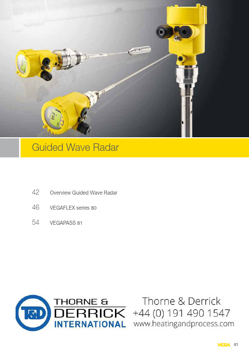
42 Overview Guided Wave Radar 46VEGAFLEX series 8054VEGAPASS 81Area of applicationThe TDR sensors of the VEGAFLEX series are suitable for level measurement in liquids and bulk solids. In liquids, they can also detect the interface bet-ween two products. They measure liquids reliably, even under high pressure and extreme temperatures. They can be used in simple as well as in aggres-sive liquids and are suitable for applications with stringent hygiene require-ments. The sensors measure light as well as heavy bulk solids with absolute reliability, even in the presence of dust and noise, and without being affected by buildup or condensation.Measuring principleHigh-frequency radar pulses are coupled onto a cable (solids) or rod (liquids) and guided along the probe. The pulse is reflected by the product surface. The instrument calculates the level from the running time of the radar pulsesand the entered tank height.AdvantagesTDR sensors operate independently of noise, pressure or temperature fluctuations and are also completely unaffected by changes in density, foaming, steam or dust. Buildup on the probe or on the container wall does not affect the measurement either. This allows simple, straightforward system design and engineering. The menu-driven adjustment routines allow simple, time-saving and confident setup.123① Cable version for process temperature -20 … +200 °C ② Rod version ③ Coax versionrestrictions./configuratorInstrument documentation and drawings: /downloadsMounting accessories, welded sockets and housing overview: Chapter AccessoryDelivery time:VEGAFLEX 81TDR sensor for continuous level and interface measurement of liquids Application areaThe VEGAFLEX 81 level sensor measures maintenance-free all kind of liquids. Even in applications with vapour, buildup, foam generation and condensation, the sensor delivers precise and reliable measured values. The VEGAFLEX 81 is the economical solution for various level and interface measurements.Your benefit−The guided adjustment enables a simple, time-saving and reliable setup−Comprehensive diagnostic possibilities ensure a maintenance-free operation and hence a high plant availability−Shortenable probes offer a simple standardisation and highest flexibility in the planning Technical data Version:exchangeable cable (ø 2 mm, ø 4 mm)exchangeable rod (ø 8 mm, ø 12 mm)coax (ø 21.3, mm, ø 42 mm)Measuring range:cable probe up to 75 m rod probe up to 6 m coax probe up to 6 m Process fitting:thread from G¾, ¾ NPT flanges from DN 25, 1"Process temperature:-40 … +200 °C-60…+150°C for volatile substances, e.g. AmmoniaProcess pressure:-1 …+40 bar (-100 … +4000 kPa)Accuracy:±2 mmScopeA Europe ......................................................................................................................................................................................Length (from seal surface)Cable ø2 mm/316 (500-75000 mm) per 100 mmRod ø8 mm/316L (300-6000 mm) per 100 mmRod ø12 mm/316L (300-4000 mm) per 100 mmCoax ø21.3mm/316L (300-6000 mm) per 100 mmCoax Ø42.2mm/316L (300-6000 mm) per 100 mm12① Cable version ② Rod version ③ Flange versionrestrictions./configuratorInstrument documentation and drawings: /downloadsMounting accessories, welded sockets and housing overview: Chapter AccessoryDelivery time:VEGAFLEX 82TDR sensor for continuous level measurement of bulk solidsApplication areaThe VEGAFLEX 82 level sensor measures maintenance-free light and heavy-weight bulk solids. Even in applications with strong dust generation,condensation or buildup, the sensor delivers precise and reliable measured values. The VEGAFLEX 82is an economical and reliable solution for your application.Your benefit−The guided adjustment enables a simple, time-saving and reliable setup−Shortenable probes offer a simple standardisation and highest flexibility in the planning−Virtually all bulk solids can be measured with the automatic probe end tracking Technical data Version:exchangeable cable (ø 4 mm, ø 6 mm)exchangeable rod (ø 16 mm)Measuring range:cable probe up to 75 m rod probe up to 6 m Process fitting:thread from G¾, ¾NPT flanges from DN 25, 1"Process temperature:-40 … +200 °CProcess pressure:-1 … +40 bar (-100 … +4000 kPa)Accuracy:±2 mmScopeA Europe ...................................................................................................................................................................................Length (from seal surface)Cable ø4 mm/316 (500-75000 mm) per 100 mmCable ø6 mm/316 (500-75000 mm) per 100 mmRod ø16 mm/316L (300-6000 mm) per 100 mm123① Version / Material: Rod (ø 10 mm) / PFA② Version / Material: Cable (ø 4 mm) with gravity weight / PFA③ Version / Material: Exchangeable rod (ø 8 mm) / 1.4435 (Basle Standard 2)restrictions./configuratorInstrument documentation and drawings: /downloadsMounting accessories, welded sockets and housing overview: Chapter AccessoryDelivery time:VEGAFLEX 83TDR sensor for continuous level and interface measurement of liquids Application areaThe VEGAFLEX 83 level sensor measures maintenance-free agressive liquids or liquid media with highest hygienic requirements. Even in applications with vapour, buildup, foam generation and condensation, the sensor delivers precise andreliable measured values. The VEGAFLEX 83 is the economical and ideal solution for your application.Your benefit−The guided adjustment enables a simple, time-saving and reliable setup −The gap-free hygienic design ensures simple and reliable cleanability −The maintenance-free operation increases the plant efficiency Technical data Version:cable (ø 4 mm)rod (ø 8 mm, ø 10 mm)Measuring range:cable probe up to 32 m rod probe up to 4 m Process fitting:flanges from DN 25, 1"hygienic fittings Process temperature:-40 … +150 °CProcess pressure:-1 … +16 bar (-100 … +1600 kPa)Accuracy:±2 mmScopeA Europe ...................................................................................................................................................................................Length (from seal surface)Cable ø4 mm / PFA isolated (500-32000 mm) per 100 mmRod ø10 mm/PFA insulated (300-4000 mm) per 100 mmRod ø8 mm/1.4435 Ra < 0.76 µm (BN2) (300-4000 mm) per 100 mm132 ø 16 mm (0.63")(0.84")① Version: -20 … +250 °C; coax ② Version: -196 … +280 °C; rod ③ Version: -196 … +450 °C; cablerestrictions./configuratorInstrument documentation and drawings: /downloadsMounting accessories, welded sockets and housing overview: Chapter AccessoryDelivery time:VEGAFLEX 86TDR sensor for continuous level and interface measurement of liquids Application areaThe VEGAFLEX 86 level sensor measures maintenance-free all liquids under extreme pressure and temperature conditions. Even in applications with buildup, foam generation and condensation, the sensor delivers precise and reliable measured values. In saturated steam applications, a special reference probe ensures a density-independent measurement. The VEGAFLEX 86 offers an economical level and interface measurement for your application.Your benefit−The guided adjustment enables a simple, time-saving and reliable setup−Comprehensive diagnostic possibilities ensure a maintenance-free operation and hence a high plant availability−The maintenance-free operation increases the plant efficiency Technical data Version:exchangebale cable (ø2 mm, ø 4 mm)exchangeable rod (ø 16 mm, ø 8 mm)coax (ø 42 mm, ø 21.3 mm)Measuring range:cable probe up to 75 m rod probe up to 6 m coax probe up to 6 m Process fitting:thread from G¾, ¾ NPT flanges from DN 25, 1"Process temperature:-196 … +450 °CProcess pressure:-1 … +400 bar (-100 … +40000 kPa)Accuracy:±2 mmScopeA Europe ...................................................................................................................................................................................Length (from seal surface)Cable ø4 mm / 316 (500-60000 mm) per 100 mmRod ø8 mm/316L (300-6000 mm) per 100 mmRod ø16 mm/316L (300-4000 mm) per 100 mmCoax ø21.3mm/316L (300-6000 mm) per 100 mmCoax ø42.2mm/316L (300-6000 mm) per 100 mmVersion: side - side / two connections Additional instrument options and possible restrictions./configurator Instrument documentation and drawings: /downloadsMounting accessories, welded sockets and housing overview:Chapter AccessoryVEGAPASS 81Bypass for continuous level measurement of liquidsApplication areaThe combination of VEGAPASS 81 with VEGAFLEX enables a continuous level measurement outside the vessel. The bypass consists of a standpipe which is mounted as communicating vessel laterally to the vessel via two process fittings. This kind of mounting ensures that the level in the standpipe and the vessel are the same.Your benefit−Maintenance-free system without mechanically moving parts−Simple, robust and proven mechanical constructionTechnical dataVersion:according to ASME or PEDProcess temperature:-196 ... +450 °C; dependent on the installedsensorProcess pressure:0 ... 250 bar; dependent on the installedsensorProcess fitting vessel:flanges from DN 20, 1"Measuring range:up to 4 mClassificationD Pressure device directive 97/23/EC /PED 97/23/EC .............................................................................................................Center - Center (M)Ø60.3x2 mm /316L (300-4000 mm) per 100 mmØ60.3x2.77 mm (2"Schedule 10)/316L (300-4000 mm) per 100 mmØ88.9x2 mm / 316L (300-4000 mm) per 100 mmØ88.9x3.05 mm (3"Schedule 10)/316L (300-4000 mm) per 100 mmDistance vessel connections 90° displaced (L)Ø60.3x2 mm /316L (300-4000 mm) per 100 mmØ60.3x2.77 mm (2"Schedule 10)/316L (300-4000 mm) per 100 mmØ88.9x2 mm / 316L (300-4000 mm) per 100 mmØ88.9x3.05 mm (3"Schedule 10)/316L (300-4000 mm) per 100 mm。
陶瓷天线 参数解读

陶瓷天线参数解读陶瓷天线是一种利用陶瓷材料制成的天线,其具有优良的高频特性、稳定的物理性能和良好的耐高温性能。
在现代通信领域,陶瓷天线因其独特的性能优势而被广泛应用于移动通信设备、卫星通信、雷达系统等领域。
本文将从陶瓷天线的性能特点、制作工艺以及参数解读等方面进行详细介绍。
一、性能特点1. 高频特性:陶瓷天线能够在高频段实现较好的信号传输效果,具有较高的频带宽度和较低的传输损耗,适用于高频率和大带宽的信号传输。
2. 耐高温性能:陶瓷天线材料具有较好的耐高温性能,可以在高温环境下长时间稳定工作,适用于各种恶劣环境下的应用场景。
3. 稳定的物理性能:陶瓷天线具有良好的尺寸稳定性和机械强度,能够在振动、冲击等环境下保持稳定的工作性能。
二、制作工艺1. 陶瓷材料选择:陶瓷天线通常采用氧化铝陶瓷、氮化硼陶瓷等作为基础材料,这些材料具有优异的介电特性和机械性能。
2. 成型工艺:首先将选定的陶瓷材料进行粉碎、混合等处理,然后通过注射成型、压制成型等工艺形成天线的外形结构。
3. 烧结工艺:经过成型的陶瓷坯体需要进行高温烧结,以实现陶瓷结构的致密化和坚固化,提高其机械强度和介电特性。
4. 金属化处理:经过烧结的陶瓷天线需要进行金属化处理,通常采用真空镀膜、化学镀等工艺,以形成导电层和连接接口。
三、参数解读1. 频率范围:陶瓷天线的设计频率范围是指其在特定频段内能够稳定传输信号的频率范围,通常用于指导天线设计和选择。
2. 增益和方向性:陶瓷天线的增益表示其在特定方向上相对于理想点源天线的信号增益情况,方向性表示其在空间角度上的信号发射或接收能力。
3. 驻波比:陶瓷天线的驻波比用于描述其输入端的匹配情况,通常要求其驻波比尽可能小,以提高信号传输效率。
4. 电阻和阻抗:陶瓷天线的电阻是指其在特定频率下的电阻值,阻抗是指其输入端的阻抗匹配情况,通常在50欧姆左右。
陶瓷天线因其优良的高频特性、稳定的物理性能和良好的耐高温性能而受到广泛关注和应用。
ZM5825 系列 Wi-Fi+BLE 模组数据手册说明书
©2023 Guangzhou ZHIYUAN Electronics Co., Ltd.ZM5825系列Wi-Fi+BLE 模组数据手册Wi-Fi+BLE 二合一无线收发模组DS01010101 1.2 Date:2023/8/31———————————— 产品特性 ◆ 频率范围:2400~2483.5MHz ◆ 无线协议:IEEE 802.11 b/g/n BEL 5.1 ◆ 工作电压:3.0~3.6 V◆ 发射功率:************************** *************◆ 接收性能:************************************************************◆ 通信接口:SDIO (@Wi-Fi )UART (@BLE ) ◆ 温度范围:-40~+85℃————————————— 订购信息型号 射频输出 封装尺寸(mm) ZM5825E IPEX 连接器 18×25×2.7 ZM5825P PCB 天线 18×25×2.7 ZM5825S邮票孔12×12×2.1—————————————— 概述 ZM5825系列Wi-Fi 模组是广州致远电子股份有限公司开发的高性能Wi-Fi+BLE 模组产品。
产品支持IEEE802.11 b/g/n 三种Wi-Fi 通信协议,支持无线热点、无线客户端两种工作模式,采用20MHz/40MHz 工作带宽,可以提供最大150Mbit/s 物理层速率。
ZM5825系列Wi-Fi 模组将完整的射频收发电路集成在一个模组上。
模组的射频输出支持IPEX 座连接外部天线或者直接使用模组自带的PCB 天线模组;也可选择邮票孔进行射频输出,使用十分灵活,用户可以根据自己的需求进行选择。
模组与主控设备通过UART 和SDIO 进行通信,简单方便,可以帮助用户产品更快的投入市场,增加用户产品的竞争力。
成都亿佰特电子科技有限公司E72-2G4M23S1A ZigBee 6LoWPAN无线模块产品规格书
E72-2G4M23S1A产品规格书CC2630+PA+LNA ZigBee 6LoWPAN 无线模块第一章概述1.1 简介E72-2G4M23S1A是基于美国德州仪器(TI)生产的CC2630为核心自主研发的最大发射功率为100mW的小体积贴片型ZigBee、6LoWPAN无线模块,采用24MHz工业级高精度低温漂有源晶振。
CC2630芯片内部集成有 128KB 系统内可编程闪存和 8KB 缓存静态RAM(SRAM)与ZigBee、6LoWPAN无线通信协议,由于其内部具有独特的超低功耗传感器控制器,因此非常适合连接外部传感器。
在原有基础上内置了TI配套的射频范围扩展器CC2592,其内置了PA与LNA,使得最大发射功率达到100mW的同时接收灵敏度也获得进一步的提升,在整体的通信稳定性上较没有功率放大器与低噪声放大器的产品大幅度提升。
由于该模块是纯硬件类SoC模块,需要用户对其编程后方可使用。
1.2 特点功能⚫内置PA+LNA,理想条件下,通信距离可达1.5km;⚫最大发射功率100mW,软件多级可调;⚫内置ZigBee、6LoWPAN协议栈;⚫内置TI原装射频范围扩展器CC2592;⚫内置32.768kHz时钟晶体振荡器;⚫支持全球免许可ISM 2.4GHz频段;⚫内置高性能低功耗Cortex-M3与 Cortex-M0双核处理器;⚫丰富的资源,128KB FLASH,28KB RAM;⚫支持2.0~3.6V供电,大于3.3V供电均可保证最佳性能;⚫工业级标准设计,支持-40~+85℃下长时间使用;⚫双天线可选(PCB/IPX),用户可根据自身需求选择使用。
1.3 应用场景⚫智能家居以及工业传感器等;⚫安防系统、定位系统;⚫无线遥控,无人机;⚫无线游戏遥控器;⚫医疗保健产品;⚫无线语音,无线耳机;⚫汽车行业应用。
第二章规格参数2.1 极限参数主要参数性能备注最小值最大值电源电压(V)0 3.8 超过3.8V 永久烧毁模块阻塞功率(dBm)- 10 近距离使用烧毁概率较小工作温度(℃)-40 +85 工业级2.2 工作参数主要参数性能备注最小值典型值最大值工作电压(V) 1.8 3.3 3.8 ≥3.3V 可保证输出功率通信电平(V) 3.0 使用5V TTL 有风险烧毁工作温度(℃)-40 - +85 工业级设计工作频段(GHz) 2.402 - 2.480 支持ISM 频段功耗发射电流(mA)182.5 瞬时功耗接收电流(mA)11.1休眠电流(μA) 1.4 软件关断最大发射功率(dBm)22.6 23.0 23.2接收灵敏度(dBm)-100.5 -102.0 -103.5 空中速率为250kbps空中速率(bps)250k - 1M 用户编程控制主要参数描述备注参考距离1500m 晴朗空旷,天线增益5dBi,高度2.5米,空中速率250kbps 晶振频率24MHz/32.768KHz支持协议ZigBee封装方式贴片式接口方式 1.27mmIC全称CC2630F128RGZRFLASH 128KBRAM 28KB内核Cortex-M3+Cortex-M0外形尺寸17.5*33.5 mm天线接口PCB/IPEX 等效阻抗约50Ω第三章机械尺寸与引脚定义引脚序号引脚名称引脚方向引脚用途1、2、3 GND 地线,连接到电源参考地4 DIO_0 输入/输出通用IO口,传感器控制器(详见CC26xx 手册)5 DIO_1 输入/输出通用IO口,传感器控制器(详见CC26xx 手册)6 DIO_2 输入/输出通用IO口,传感器控制器(详见CC26xx 手册)7 DIO_3 输入/输出通用IO口,传感器控制器(详见CC26xx 手册)8 DIO_4 输入/输出通用IO口,传感器控制器(详见CC26xx 手册)9 DIO_5 输入/输出高驱动通用IO口,传感器控制器(详见CC26xx 手册)10 DIO_6 输入/输出高驱动通用IO口,传感器控制器(详见CC26xx 手册)11 DIO_7 输入/输出高驱动通用IO口,传感器控制器(详见CC26xx 手册)12 DIO_8 输入/输出通用IO口,详见CC26xx 手册)13 DIO_9 输入/输出通用IO口,详见CC26xx 手册)14 DIO_10 输入/输出通用IO口,详见CC26xx 手册)15 DIO_11 输入/输出通用IO口,详见CC26xx 手册)16 DIO_12 输入/输出通用IO口,详见CC26xx 手册)17 DIO_13 输入/输出通用IO口,详见CC26xx 手册)18 DIO_14 输入/输出通用IO口,详见CC26xx 手册)19 DIO_15 输入/输出通用IO口,详见CC26xx 手册)20 JTAG_TMS 输入/输出JTAG_TMSC, 高驱动能力(详见CC26xx 手册)21 JTAG_TCK 输入/输出JTAG_TCKC, 高驱动能力(详见CC26xx 手册)22 DIO_16 输入/输出高驱动通用IO口,JTAG_TDO(详见CC26xx 手册)23 DIO_17 输入/输出高驱动通用IO口,JTAG_TDI(详见CC26xx 手册)24 DIO_18 输入/输出通用IO口,详见CC26xx 手册)25 DIO_19 输入/输出通用IO口,详见CC26xx 手册)26 DIO_20 输入/输出通用IO口,详见CC26xx 手册)27 GND 地线,连接到电源参考地28 DIO_21 输入/输出通用IO口,详见CC26xx 手册)29 VCC 电源,1.8~3.8V30 DIO_22 输入/输出通用IO口,详见CC26xx 手册)31 DIO_23 输入/输出通用IO口,传感器控制器,数模(详见CC26xx 手册)32 nRESET 输入复位,低电平(详见CC26xx 手册)33 DIO_24 输入/输出通用IO口,传感器控制器,数模(详见CC26xx 手册)34 DIO_25 输入/输出通用IO口,传感器控制器,数模(详见CC26xx 手册)35 DIO_26 输入/输出通用IO口,传感器控制器,数模(详见CC26xx 手册)36 DIO_27 输入/输出通用IO口,传感器控制器,数模(详见CC26xx 手册)37 DIO_28 输入/输出通用IO口,传感器控制器,数模(详见CC26xx 手册)38 DIO_29 输入/输出通用IO口,传感器控制器,数模(详见CC26xx 手册)39 DIO_30 输入/输出通用IO口,传感器控制器,数模(详见CC26xx 手册)40、41、42 GND 地线,连接到电源参考地第四章基本操作4.1硬件设计⚫推荐使用直流稳压电源对该模块进行供电,电源纹波系数尽量小,模块需可靠接地;⚫请注意电源正负极的正确连接,如反接可能会导致模块永久性损坏;⚫请检查供电电源,确保在推荐供电电压之间,如超过最大值会造成模块永久性损坏;⚫请检查电源稳定性,电压不能大幅频繁波动;⚫在针对模块设计供电电路时,往往推荐保留30%以上余量,有整机利于长期稳定地工作;⚫模块应尽量远离电源、变压器、高频走线等电磁干扰较大的部分;⚫高频数字走线、高频模拟走线、电源走线必须避开模块下方,若实在需要经过模块下方,假设模块焊接在Top Layer,在模块接触部分的Top Layer铺地铜(全部铺铜并良好接地),必须靠近模块数字部分并走线在Bottom Layer;⚫假设模块焊接或放置在Top Layer,在Bottom Layer或者其他层随意走线也是错误的,会在不同程度影响模块的杂散以及接收灵敏度;⚫假设模块周围有存在较大电磁干扰的器件也会极大影响模块的性能,跟据干扰的强度建议适当远离模块,若情况允许可以做适当的隔离与屏蔽;⚫假设模块周围有存在较大电磁干扰的走线(高频数字、高频模拟、电源走线)也会极大影响模块的性能,跟据干扰的强度建议适当远离模块,若情况允许可以做适当的隔离与屏蔽;⚫通信线若使用5V电平,必须串联1k-5.1k电阻(不推荐,仍有损坏风险);⚫尽量远离部分物理层亦为2.4GHz的TTL协议,例如:USB3.0;⚫天线安装结构对模块性能有较大影响,务必保证天线外露,最好垂直向上。
2.4G 陶瓷天线

Temperature
3sec
1. No visible mechanical damage
2. Central Freq. change :within ±6%
3. No disconnection or short circuit.
Resistance to Low Temperature
1. No visible mechanical damage 2. Central Freq. change :within ±6% 3. No disconnection or short circuit.
1. No visible mechanical damage
2. Central Freq. change :within ±6%
Phase Temperature(℃) Time(min)
1
+85±5℃
30±3
2
Room
Within
Temperature
3sec
3
Байду номын сангаас
‐40±2℃
30±3
4
Room
Within
10 ( @ 260℃)
sec.
Polarization Azimuth Beamwidth
Termination
Linear Omni‐directional Ni / Sn (Leadless)
Remark : Bandwidth & Peak Gain was measured under evaluation board of next page
Temperature: 85±5℃ Duration: 1000±12hrs The chip shall be stabilized at
滤波器微波介质滤波器
滤波器微波介质滤波器浙江正原电气股份有限公司ZHEJIANG ZHENGYUAN ELECTRIC CO.,LTD多层片状陶瓷天线MULTI-LAYER CHIP TYPE CERAMIC ANTENNA技术条件SPECIFICATION产品型号LA5220P2450-A04Part Number用户名称版本号 V1.1发送日期拟制发送人审核页数 8 批准地址:中国浙江省嘉兴市经济开发区塘汇工业区正原路1号ADD:No.1 Zhengyuan Road,Tanghui IndustrialZone,Jiaxing,Zhejiang,ChinaTEL:0086-573-3651818FAX:0086-573-36518581产品(LA5220P2450-A04)规格书版本更改记录版本号更改记录拟制批准日期首次发行王剑强陆德龙 2007.06.09 V1.0Land Pattern 尺寸修改,以免SMT时王剑强陆德龙 2007.06.25 V1.1 电极间短路备注:1、更改产品电性能指标时,版本号需更换(V1.0换为V2.0、V3.0……);2、更改产品测试方法(包括可靠性测试条件),或更改使用条件时,当前版本号加系列(V1.0换为V1.1、V1.2……)。
2? 概述 Introduction"正原"微波多层片状陶瓷天线LA系列产品设计用于WLAN、蓝牙天线、PHS~手机多频天线, GPS等小体积SMD片式设计。
"ZHENG YUAN" Microwave Multi-Layer Chip Type Ceramic AntennaLA series are designed to be used in WLAN、Bluetooth、PHS、Multiple-band Mobile phone antenna, GPS, etc and compact size SMD chip design.? 型号 Part NumberLA 5220 P 2450 - A04产品名称,编号A04/Proudct Name: A04中心工作频率/ Center Frequency: 2450MHz结构系列/Structure Series产品尺寸/Size:5.2×2.0×1.2多层结构天线/Multi-layer Antenna? 外型尺寸 Dimensions(Unit:mm)? 测试电路 Evaluation Board3? 电气性能 Electrical Characteristics(项目) Specifications (特性) Item No.5.1 Working Central Frequency 中心工作频率 2450 MHz 5.2 Band Width 通带宽度 ?75 MHz ( 2375,2525MHz ) 5.3 Gain 增益 0,2 dBi 5.4 V.S.W.R (in BW) 驻波比 ?2.0Polarization 极化方式 5.5 Linear 线性Azimuth Beam width 方位角 5.6 Omni-directional 全向Impedance 阻抗 5.7 50 Ω *本天线在应用PCB上通过设计匹配电路,将天线工作频率调整到2.45GHz中心工作频率。
- 1、下载文档前请自行甄别文档内容的完整性,平台不提供额外的编辑、内容补充、找答案等附加服务。
- 2、"仅部分预览"的文档,不可在线预览部分如存在完整性等问题,可反馈申请退款(可完整预览的文档不适用该条件!)。
- 3、如文档侵犯您的权益,请联系客服反馈,我们会尽快为您处理(人工客服工作时间:9:00-18:30)。
The device should satisfy the electrical characteristics specified in paragraph 8.1~8.6 after dropping
onto the hard wooden board from the height of 100cm for 3 times each facet of the 3 dimensions of the
送样日期 Formed On:2012.06.13 Document Version
LA5220P2450-A04 V1.5
嘉兴佳利电子股份有限公司
阿里巴巴 - 1 -
JIAXING GLEAD ELECTRONICS CO.,LTD
中国浙江省嘉兴市经济开发区塘汇街道正原路 66 号
No.66 ZhengyuanRoad, Tanghui Street,Jiaxing,Zhejiang,China TEL:0086-573-83651818 FAX:0086-573-83651858
拟制 Prepared by: 审核 Checked by : 批准 Approved by:
JIAXING GLEAD ELECTRONICS CO.,LTD
7. 方向图
LTCC 多层天线 LA5220P2450-A04 Radiation Pattern
嘉兴佳利电子股份有限公司
阿里巴巴 - 6 -
the vibration of 10 to 55Hz with amplitude of 1.5mm for 2 hours each in X , Y and Z directions. 9.2 耐跌落冲击 Drop Shock
在 100cm 高度处按 X,Y,Z 三个面分别自由跌落在木制地板上共 3 次后测试符合表 8.1~8.6 规 定。
LTCC 多层天线 LA5220P2450-A04
嘉兴佳利电子股份有限公司
Jiaxing Glead Electronics Co.,Ltd
产品技术规格书
SPECIFICATION
产品型号 PART NO:
LA5220P2450-A04
客户料号 CUSTOMER PART NO:
客户确认 CUSTOMER APPROVED BY: 确认日期 APPROVED DATE:
嘉兴佳利电子股份有限公司
阿里巴巴 - 7 -
JIAXING GLEAD ELECTRONICS CO.,LTD
LTCC 多层天线 LA5220P2450-A04
9.5 耐弯曲试验
Bending
Resist Test 将产品按图焊在 1.6±0.2mm 的 PCB 板中间,由箭头方向施
LTCC 多层天线 LA5220P2450-A04
目录
序号
项 目 Item
1 规格书版本更改记录 VerFra bibliotekion rejigger track record
2 概述
INTRODUCTION
3 型号
Part Number
4 外形尺寸
Dimension
5 测试电路
Evaluation Board
6 电气性能
No.
Item (项目)
8.1
Central Frequency 中心频率
Post Dependability Tolerance
(可靠性试验后允许附加误差)
±25 MHz
8.2
Band Width 通带宽度
±20 MHz
8.3
Gain 增益
±0.2 dBi
8.4
V.S.W.R (in BW) 驻波比
device. 9.3 耐焊接热 Solder Heat Proof
能承受经 120~150℃的温度预热 120 秒后,在 255℃+10℃的焊锡浸 5±0.5 秒,或 300℃-10℃的 电烙铁焊接 3±0.5 秒,焊接面无损伤。
The device should be satisfied after preheating at 120℃~150℃ for 120 seconds and dipping in soldering Sn at 255℃+10℃ for 5±0.5 seconds,or electric iron 300℃-10℃ for 3±0.5 seconds,
产品尺寸/Size:5.2×2.0×1.2 多层结构天线/Multi-layer Antenna
⒊ 外型尺寸 Dimensions(Unit:mm)
⒋ 测试电路和匹配电路
Evaluation Board and Matching Circuits
*以上测试电路仅用于测试天线本振频率,实际应用应根据不同 PCB 设计匹配电路来达到 2.45GHz 工作频率
12 包装尺寸 Packaging and Dimensions 13 附页:样品测试数据 Sample Test Data
页 Page P3 P4 P4 P4 P4 P5 P5 P6 P7
P7~P8 P8 P9 P10
嘉兴佳利电子股份有限公司
阿里巴巴 - 2 -
嘉兴佳利电子股份有限公司
阿里巴巴 - 3 -
JIAXING GLEAD ELECTRONICS CO.,LTD
LTCC 多层天线 LA5220P2450-A04
⒈ 概述 INTRODUCTION
"佳利"微波多层陶瓷天线 LA 系列产品设计用于 WLAN、WiFi、蓝牙、PHS,手机
力:1mm/S,弯曲距离:1.5mm,保持 5±1S,产品金属层无脱落。
Weld the product to the center part of the PCB with the thickness 1.6 ± 0.2mm as the illustration shows, and keep exerting force arrow-ward on it at speed of :1mm/S , and hold for 5±1S at the
compact size SMD chip design. ⒉ 型号 Part Number
LA 5220 P 2450 – A04
产品名称,编号 A04/Proudct Name: A04
天线频率/ Antenna Frequency: 2450 MHz
产品设计结构 P 型/Planar Structure
多频天线, FM 等小体积 SMD 片式设计。
"GLEAD" Microwave Multi-Layer Ceramic Antenna LA series are designed to be used in WLAN、WiFi、Bluetooth、PHS、 Multiple-band Mobile phone antenna, FM, etc and
±0.5
9 可靠性试验 Dependability Test
基准条件:温度范围 Temperature range
25±5℃
相对湿度范围 Relative Humidity range
55~75%RH
工作温度 Operating Temperature range -40℃~+85℃
贮藏温度 Storage Temperature range -40℃~+85℃
Specifications (特性) 2450 MHz
±75 MHz ( 2375~2525MHz ) 0~2 dBi ≤2.0
Linear 线性 Omni-directional 全向
50 Ω
⒍ 特性曲线
Characteristic curve
嘉兴佳利电子股份有限公司
阿里巴巴 - 5 -
JIAXING GLEAD ELECTRONICS CO.,LTD
LTCC 多层天线 LA5220P2450-A04
产品(LA5220P2450-A04)规格书版本更改记录
Version rejigger track record
版本号 Version
JIAXING GLEAD ELECTRONICS CO.,LTD
LTCC 多层天线 LA5220P2450-A04
8 可靠性试验后允许误差 Post Dependability Tolerance
经可靠性试验后允许比起始读数偏差见下表 Post Dependability Tolerance ( Refer to the table )
No.
Item (项目)
5.1 Working Central Frequency 中心工作频率
5.2
Band Width 通带宽度
5.3
Gain 增益
5.4
V.S.W.R (in BW) 驻波比
5.5
Polarization 极化方式
5.6
Azimuth Beam width 方位角
5.7
Impedance 阻抗
V1.3 增加测试 PCB 反面接地层和说明
王剑强 陆德龙 2008.04.11
V1.4 厚度改为 1.2mm±0.2mm(原 1.0mm±0.1mm) 李苏萍
陆德龙 2010.01.18
V1.5 增加 11.3 储存条件 Storage Period
李苏萍 陆德龙 2012.6.13
备注: 1、更改产品电性能指标时,版本号需更换(V1.0 换为 V2.0、V3.0……); 2、更改产品测试方法(包括可靠性测试条件),或更改使用条件时,当前版本号加系列(V1.0 换为 V1.1、V1.2……)。
更改记录 Rejigger
拟制
Prepared