帕罗肯PA-13配电隔离器
隔离配电器的现场典型应用

隔离配电器的现场典型应用隔离配电器是一种与单元组合仪表及DCS,PLC等系统配套使用,为压力变送器等需要现场供电的一次仪表提供电源回路,同线测量该一次仪表输出的电源信号,经过运算、干扰抑制等处理后,变送输出隔离的单路或双路电流或电压信号。
隔离配电器提高输入、输出、电源之间的电气隔离性能。
常见的有一入一出、一入二出、一入三出、二入二出等类型,已经广泛应用于油田、石化、制造、电力、冶金等行业的自控工程之中。
隔离配电器的现场典型应用:1、解决共地、避免干扰在大型项目改造中,经常遇到不同设备之间的共地问题,这也是产生信号干扰设备之间无法正常采集和处理的原因。
此时用户需要采用一种高密度、DIN导轨安装的低成本,高性能的仪表解决这一问题行之有效的方法就是:安装一台无缘隔离器(帕罗肯科技P/PA系列-P-0133无源信号隔离器,PA-0133无源信号隔离器),它具有无需供电,高隔离的输出通道,同时它具有价位低,高密度的安装方式,简单易行的接线方式等优势。
2、两地共享过程信号有时,用户需要在两个不同的地方同时监测一路现场信号,简单、经济的方法就是:安装一个一进两出的隔离分配器(帕罗肯PR/PG系列信号隔离分配器-PR-1127GG-D直流信号隔离分配器、PG-113/PG-114直流信号分配器《一分三、一分四》),它不仅可以隔离地回路,电机噪音及一些电子产品所造成的干扰,而且将一路信号分配成两路至四路相同或者不同的信号,这两路信号可送到不同的两个接收设备,进行监测、记录或控制。
3、增强带负载能力有时,用户需要在回路中再加一个250欧姆的负载(PID控制器),但是这样超过了回路负载600欧姆,现在简单经济的方法就是:安装一个地输入阻抗(100欧姆)高驱动负载能力(500欧姆)的2线制ECT,这样可以增强回路的负载能力,可以类似PID 控制器及其它扩展场合找到空间。
4、解决电源冲突问题有些回路中,用户需要将4线制变送器接到DCS上,但是DCS是给输入回路供电的,这样在变送器和DCS之间有个电源冲突的问题。
贝利尼蒂烈Asset Condition监测3500电压隔离器接口说明书
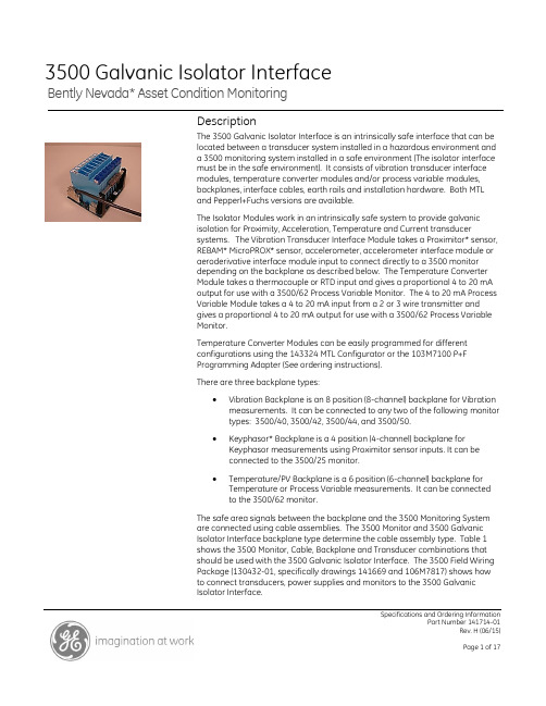
Specifications and Ordering InformationPart Number 141714-01Rev. H (06/15)Bently Nevada* Asset Condition Monitoring3500 Galvanic Isolator InterfaceDescriptionThe 3500 Galvanic Isolator Interface is an intrinsically safe interface that can be located between a transducer system installed in a hazardous environment and a 3500 monitoring system installed in a safe environment (The isolator interface must be in the safe environment). It consists of vibration transducer interface modules, temperature converter modules and/or process variable modules, backplanes, interface cables, earth rails and installation hardware. Both MTL and Pepperl+Fuchs versions are available.The Isolator Modules work in an intrinsically safe system to provide galvanic isolation for Proximity, Acceleration, Temperature and Current transducersystems. The Vibration Transducer Interface Module takes a Proximitor* sensor, REBAM* MicroPROX* sensor, accelerometer, accelerometer interface module or aeroderivative interface module input to connect directly to a 3500 monitor depending on the backplane as described below. The Temperature Converter Module takes a thermocouple or RTD input and gives a proportional 4 to 20 mA output for use with a 3500/62 Process Variable Monitor. The 4 to 20 mA Process Variable Module takes a 4 to 20 mA input from a 2 or 3 wire transmitter and gives a proportional 4 to 20 mA output for use with a 3500/62 Process Variable Monitor.Temperature Converter Modules can be easily programmed for different configurations using the 143324 MTL Configurator or the 103M7100 P+F Programming Adapter (See ordering instructions). There are three backplane types:∙Vibration Backplane is an 8 position (8-channel) backplane for Vibration measurements. It can be connected to any two of the following monitor types: 3500/40, 3500/42, 3500/44, and 3500/50.∙Keyphasor* Backplane is a 4 position (4-channel) backplane for Keyphasor measurements using Proximitor sensor inputs. It can be connected to the 3500/25 monitor.∙Temperature/PV Backplane is a 6 position (6-channel) backplane for Temperature or Process Variable measurements. It can be connected to the 3500/62 monitor.The safe area signals between the backplane and the 3500 Monitoring System are connected using cable assemblies. The 3500 Monitor and 3500 Galvanic Isolator Interface backplane type determine the cable assembly type. Table 1 shows the 3500 Monitor, Cable, Backplane and Transducer combinations that should be used with the 3500 Galvanic Isolator Interface. The 3500 Field Wiring Package (130432-01, specifically drawings 141669 and 106M7817) shows how to connect transducers, power supplies and monitors to the 3500 GalvanicIsolator Interface.Specifications:IsolatorsMTLVibrationTransducerInterfaceModule:MTL 4531TemperatureConverterModule:MTL 45752 or3 WireTransmitterModule:MTL 4541For complete specifications and approvals information please visit the MTL website:/Pepperl+FuchsVibrationTransducerInterfaceModule:KFD2-VR4-Ex1.26 TemperatureConverterModule:KFD2-UT2-Ex12 or3 WireTransmitterModule:KFD2-STC4-Ex1For complete specifications and approvals information please visit the P+F website:/BackplanesMTLEnvironmentalOperatingTemperature:-20︒C to +60︒C (-4︒F to +140︒F)continuous workingStorageTemperature-40︒C to +80︒C (-40︒F to +176︒F) RelativeHumidity:5% to 95% noncondensing ElectricalAll values assume the device is at room temperature (20︒ C) unless otherwise specified. All values are per module unless otherwise specified.Number ofchannels:VibrationBackplane(288126):EightKeyphasorBackplane(288127):FourTemperature/ProcessVariableBackplane(288128):SixSupply Voltage,Vs+20 Vdc to +35 VdcPower SupplyFuse Rating2APower SupplyConnectorsSpecifications and Ordering InformationAccommodate conductors up to14 AWGLED IndicatorsGreen: Two provided for powerindication.PermittedLocationSafe area onlyHazardous Area ApprovalsThe MTL backplanes do not require hazardous area approvals because they are in a safe area. All hazardous area wires connect directly to the isolator modules and not to the backplane. The backplane carries safe area signals only.P+FEnvironmentalOperatingTemperature:-20︒C to +60︒C (-4︒F to +140︒F)continuous workingStorageTemperature-40︒C to +70︒C (-40︒F to +176︒F) RelativeHumidity:≤ 95 % , non-condensing ElectricalAll values assume the device is at room temperature (20︒ C) unless otherwise specified. All values are per module unless otherwise specified.Number ofchannels:VibrationBackplane(103M8641):EightKeyphasorBackplane(103M8643):FourTemperature/ProcessVariable Backplane(103M8642):SixSupply Voltage,Vs+21 Vdc to +30 VdcPower SupplyFuse Rating2APower SupplyConnectors24 - 14 AWGLED IndicatorsGreen: Two provided for powerindication.Red: Two provided for faultindication.PermittedLocationSafe area onlyHazardous Area ApprovalsThe P+F backplanes do not require hazardous area approvals because they are in a safe area. All hazardous area wires connect directly to the isolator modules and not to the backplane. The backplane carries safe area signals only.Enclosure (for MTL Backplanes only) EnvironmentalAmbientTemperatureLimits-20︒ C to +50︒ C (-4︒ F to +122︒ F) PhysicalProtectionDust-tight and water-jet proof toIEC529:IP65CapacityOne backplane part number141660A01. If an enclosure forpart number 141660A02 or143320 is required, pleaseSpecifications and Ordering Informationcontact your sales or servicerepresentative for a mod. ConstructionBase: GRP (glass-fibre reinforcedpolyester)Lid: transparent high-strengthpolycarbonateFinishBase: light greyLid: transparentLid FixingCaptive fixing screwsGland FixingSide mounted gland plate,detachable for drilling by user PermittedLocationSafe area onlyMountingBy exterior surface-fixing lugs(zinc passivated steel)Weight (withoutbackplanes andisolators)3.7 kgOrdering ConsiderationsGeneralThe MTL and P+F isolator Intrinsic Safety Electrical Parameters may not allow for interchangeability with existing installations. Ensure that all Approvals requirements are met.The 3500 Galvanic Isolator Interface (Vibration) can receive inputs from the following approved Bently Nevada* transducers:3300 XL Proximitor3300 5/8mm Proximitor7200 5/8mm Proximitor330400 AccelerometerAcceleration Interface Module(p/n 23733-03)Aeroderivative Interface Module(p/n 86517) (Velocity only)(MTLBackplane version only)3300 REBAM MicroPROX7200 REBAM MicroPROXThe 3500 Galvanic Isolator Interface (Temperature) can receive inputs from the following transducers selectable with the appropriate configurator:B Type ThermocoupleE Type ThermocoupleJ Type ThermocoupleK Type ThermocoupleN Type ThermocoupleR Type ThermocoupleS Type ThermocoupleT Type Thermocouple2 Wire RTD3 Wire RTD4 Wire RTDIf thermocouples will be used, the 3500 Temperature Isolator comes with Cold Junction Compensation (CJC) Signal Connectors for the hazardous area inputs.If using thermocouples with the P+F Temperature Backplane, be sure to select Option G when ordering 103M9110. This will include the user-installed CJC Terminal Blocks. (See Ordering Information)The 3500 Galvanic Isolator Interface can be used with the following 3500 Monitors. Note the I/O module type must be External Termination unless cable assemblies with flying leads are used.▪3500/25 Keyphasor Monitor▪3500/40 Proximitor Monitor▪3500/42 Proximitor/Seismic Monitor▪3500/44 Aeroderivative Monitor▪3500/50 Tachometer Monitor▪3500/62 Process Variable Monitor▪3500/72 Rod Position MonitorSpecifications and Ordering InformationOrdering InformationFor a detailed listing of country and product specific approvals, refer to the Approvals Quick Reference Guide (document 108M1756) located at the following website:.MTL3500 MTL Galvanic Isolator Interface (Vibration) 141660-AXX-BXX-CXX-DXX-EXX-FXX-GXX-HXX-IXX-JXX A: Backplane Type0 1 8 Position Backplane –Vibration0 2 4 Position Backplane –KeyphasorB:Isolator Backplane Position 10 0No isolator0 1Isolator MTL 4531C:Isolator Backplane Position 20 0No isolator0 1Isolator MTL 4531D:Isolator Backplane Position 30 0No isolator0 1Isolator MTL 4531E:Isolator Backplane Position 40 0No isolator0 1Isolator MTL 4531F:Isolator Backplane Position 50 0No isolator0 1Isolator MTL 4531G: Isolator Backplane Position 60 0No isolator0 1Isolator MTL 4531H:Isolator Backplane Position 70 0No isolator0 1Isolator MTL 4531I:Isolator Backplane Position 80 0No isolator0 1Isolator MTL 4531J:Weatherproof Housing0 0No housing0 1 & Weatherproof housingSpare components288112Isolator MTL 453103639911& Weatherproof Housing 288766Replacement FuseNote: modification to mounting plate is required for the 4P Keyphasor Backplane3500 MTL Galvanic Isolator Interface (Temperature/PV)143320-AXX-BXX-CXX-DXX-EXX-FXX-GXXA:Isolator Backplane Position 10 0No isolator0 1Isolator MTL 4541, PV 4-20 mAinput0 3Isolator MTL 4575, K type TC B:Isolator Backplane Position 20 0No isolator0 1Isolator MTL 4541, PV 4-20 mAinput0 3Isolator MTL 4575, K type TC C:Isolator Backplane Position 30 0No isolator0 1Isolator MTL 4541, PV 4-20 mAinput0 3Isolator MTL 4575, K type TC D:Isolator Backplane Position 40 0No isolator0 1Isolator MTL 4541, PV 4-20 mAinput0 3Isolator MTL 4575, K type TC E:Isolator Backplane Position 50 0No isolator0 1Isolator MTL 4541, PV 4-20 mAinput0 3Isolator MTL 4575, K type TC F:Isolator Backplane Position 60 0No isolator0 1Isolator MTL 4541, PV 4-20 mAinput0 3Isolator MTL 4575, K type TC G:Weatherproof Housing0 0No housing0 1 & Weatherproof housingSpare components288114Isolator MTL 4575, K type TC 288416Isolator MTL 4541, PV type 4-20mA03639911& Weatherproof HousingSpecifications and Ordering Information288766Replacement Fuse& Note: modification to mounting plate is required for the 6P Temperature/PV BackplaneOrdering InformationP+F3500 P+F Galvanic Isolator Interface (Vibration)103M9109-AXX-BXX-CXX-DXX-EXX-FXX-GXX-HXX-IXX A: Backplane Type0 1 8 Position Backplane –Vibration0 2 4 Position Backplane –KeyphasorB:Isolator Backplane Position 10 0No isolator0 1P+F KFD2-VR4-Ex1.26 Isolator C:Isolator Backplane Position 20 0No isolator0 1P+F KFD2-VR4-Ex1.26 Isolator D:Isolator Backplane Position 30 0No isolator0 1P+F KFD2-VR4-Ex1.26 Isolator E:Isolator Backplane Position 40 0No isolator0 1P+F KFD2-VR4-Ex1.26 Isolator F:Isolator Backplane Position 50 0No isolator0 1P+F KFD2-VR4-Ex1.26 Isolator G: Isolator Backplane Position 60 0No isolator0 1P+F KFD2-VR4-Ex1.26 Isolator H:Isolator Backplane Position 70 0No isolator0 1P+F KFD2-VR4-Ex1.26 Isolator I:Isolator Backplane Position 80 0No isolator0 1P+F KFD2-VR4-Ex1.26 IsolatorSpare components172436P+F KFD2-VR4-Ex1.26 Isolator 103M7113Replacement Fuse 3500 P+F Galvanic Isolator Interface (Temperature/PV)103M9110-AXX-BXX-CXX-DXX-EXX-FXX-GXXA:Isolator Backplane Position 10 0No isolator0 1P+F KFD2-STC4-Ex1 PV 4-200 2P+F KFD2-UT2-Ex1TEMPERATUREB:Isolator Backplane Position 20 0No isolator0 1P+F KFD2-STC4-Ex1 PV 4-200 2P+F KFD2-UT2-Ex1TEMPERATUREC:Isolator Backplane Position 30 0No isolator0 1P+F KFD2-STC4-Ex1 PV 4-200 2P+F KFD2-UT2-Ex1TEMPERATURED:Isolator Backplane Position 40 0No isolator0 1P+F KFD2-STC4-Ex1 PV 4-200 2P+F KFD2-UT2-Ex1TEMPERATUREE:Isolator Backplane Position 50 0No isolator0 1P+F KFD2-STC4-Ex1 PV 4-200 2P+F KFD2-UT2-Ex1TEMPERATUREF:Isolator Backplane Position 60 0No isolator0 1P+F KFD2-STC4-Ex1 PV 4-200 2P+F KFD2-UT2-Ex1TEMPERATUREG:Thermocouple CJC Term Blocks0 0None (RTDs)0 1TC CJC Term BlocksSpare components102M4383P+F KFD2-UT2-Ex1 TEMPERATURE 103M2798P+F KFD2-STC4-Ex1 PV 4-20103M7113Replacement Fuse103M9036P+F Thermocouple CJC TermBlockSpecifications and Ordering InformationConfiguratorsMTL143324-AXXA:Configurator Type0 1MTL PCS45/PCL45USB(software and cable)P+F103M7100P+F K-ADP-USB (Cable only) Software can be downloaded free of charge from P+F:/Cables3500 Galvanic Isolator Interface Cable (Vibration)141707-AXXXX-BXXA:Cable Length (ft)0 0 0 5 5 ft0 0 0 77 ft0 0 1 010 ft0 0 1 515 ft0 0 2 525 ft0 0 5 050 ft0 1 0 0100 ftB:Assembly0 1 Not assembled0 2Assembled0 3Assembled – Flying lead (noconnector to 3500 monitor)3500 Galvanic Isolator Interface Cable (Keyphasor) 141708-AXXXX-BXXA:Cable Length (ft)0 0 0 5 5 ft0 0 0 77 ft0 0 1 010 ft0 0 1 515 ft0 0 2 525 ft0 0 5 050 ft0 1 0 0100 ftB:Assembly0 1 Not assembled0 2Assembled0 3Assembled – Flying lead (noconnector to 3500 monitor) 3500 Galvanic Isolator Interface Cable (Temperature/PV) 141709-AXXXX-BXXA:Cable Length (ft)0 0 0 5 5 ft0 0 0 77 ft0 0 1 010 ft0 0 1 515 ft0 0 2 5 25 ft0 0 5 050 ft0 1 0 0100 ftB:Assembly0 1 Not assembled0 2Assembled0 3Assembled – Flying lead(noconnector to 3500monitor)3500 Galvanic Isolator Interface Cable (Aeroderivative) 141710-AXXXX-BXXA:Cable Length (ft)0 0 0 5 5 ft0 0 0 77 ft0 0 1 010 ft0 0 1 515 ft0 0 2 525 ft0 0 5 050 ft0 1 0 0100 ftB:Assembly0 1 Not assembled0 2Assembled0 3Assembled – Flying lead (noconnector to 3500 monitor) Documents3500 Galvanic Isolator Interface Documentation 141706-013500 Galvanic Isolator InterfaceManual130432-013500 Field Wiring PackageSpecifications and Ordering InformationTables and FiguresTable 1: 3500 Galvanic Isolator Interface – 3500 Monitor, Cable, Backplane and TransducerType Combinations## The 3500 Keyphasor Module is a half-height module. The top and bottom modules are connected separately.### /50 Tachometer: Positions 2 & 4 or 6 & 8 not available.Specifications and Ordering InformationFigure 1: Dimensions of the MTL Vibration Galvanic Isolator Module, 288112Specifications and Ordering InformationFigure 3: Dimensions of the MTL 4P Backplane, Keyphasor (288127)Specifications and Ordering InformationFigure 4: Dimensions of the MTL Temperature Galvanic Isolator Module, 288114Specifications and Ordering InformationMillimetre (inch)Figure 5: Dimensions of the MTL Process Variable Galvanic Isolator Module, 288416Specifications and Ordering InformationFigure 6: Dimensions of the MTL 6P Backplane, Temperature/PV (288128)Specifications and Ordering InformationMillimetre (inch)Figure 7: Dimensions of the MTL WP Housing (03639911)Specifications and Ordering InformationFigure 8: Dimensions of the P+F Isolator Modules (172436, 102M4383, 103M2798)Specifications and Ordering InformationSpecifications and Ordering InformationFigure 9: Dimensions of the P+F 8P Backplane, Vibration (103M8641)Figure 10: Dimensions of the P+F 4P Backplane, Keyphasor (103M8643)Specifications and Ordering InformationFigure 11: Dimensions of the P+F 6P Backplane, Temperature/PV (103M8642)* Denotes a trademark of Bently Nevada, Inc., a wholly owned subsidiary of General Electric Company.© 2002 – 2015 Bently Nevada, Inc. All rights reserved.Printed in USA. Uncontrolled when transmitted electronically.1631 Bently Parkway South, Minden, Nevada USA 89423Phone: 775.782.3611 Fax: 775.215.2873/。
某洗浴中心消防联动及应急照明设计图

PA-8000系统调试作业指导书(通用-济南站)
PA-8000 大铁路系统调试作业指导书试用版-济南站控制软件(共25页)编制:审核:批准:目录1.单机设备功能2.组网通信功能3.信源及广播区设置4.信源广播功能5.应急广播功能6.可编程电源控制器(TBA-8420)的延时上电功能7.功放检测控制器(TBA-8650)的检测倒机功能8.消防紧急回路选择器(TBA-8130)的消防广播功能9.噪声检测装置(TBA-3850)的设备参数设置及噪检功能10.负载监测控制器(TBA-8640)的设备参数设置1- 单机设备功能系统搭建完成后,对单个设备依次进行上电,然后确认每个设备在未组网时的上电状态是否合格。
①透镜状态栏“正常”灯闪烁。
②开机指示栏依次点亮后,第1~5路灯关闭,第③延时时间栏依次显示延时时间后,自动变为“④按键背景灯常亮。
①开机后有“嘀”声。
②显示屏显示“系统组网”状态 ③工作灯常亮。
①开机后有“嘀”声。
②状态显示中“工作”灯闪亮。
①开机后有“嘀”声。
②广播区通道指示灯和话筒灯常亮3秒后关闭。
工作灯常亮第6路灯常亮显示为ON按键背景灯常亮正常灯闪烁 工作灯常亮工作灯常亮①第1路选通灯常亮。
②显示屏显示电平数值。
例如:“③手动调节“平可以增加和减少。
①开机后有继电器吸合声音。
②音量指示灯闪亮一下后关闭,后话筒灯常亮。
①上电后,工作指示灯、选通灯等部分显示灯会循环闪烁。
②然后状态显示中的部分显示灯会常亮,如下所示:③ 按键指示灯保持常亮状态。
(常亮灯的颜色为绿色)工作灯、通信灯、查询灯常亮“1~5”灯常亮 按键背景灯常亮③显示屏最终显示“音量”和“温度”。
①上电后风扇转动3~5秒后停止。
②输出灯闪烁一下,显示地址信息①开机后有继电器吸合声音。
②工作灯常亮,四路输出显示“00”。
工作灯常亮③如果连接噪检探头,相应的指示电平数值会变化。
2-组网通信功能1)根据下表中的说明,对单机设备进行组网操作,并确认组网后状态是否合格。
①开机时常按“9”和“10”进行组网,网管检测装置TBA-3830会发出“嘀”声,并在网管检测设备中有显示,①开机时常按编码器旋钮。
某商场电气配电图及风机控制原理图

PASS M0介绍

断路器
概述:
用于PASS M0装置的断路器其原理为自能式气自 吹SF6断路器。所需的合闸能量储存在BLK222驱 动装置的弹簧中(见FM431E)。分闸弹簧位于每相 中,随时能够提供开关分闸所需的能量。 断路器舱主要包括: (2)断路器与组合式隔离刀动触点连接的静触静 触头; (3)动触头(4)喷口(5)触头弹簧(6)开关 销(7)上防护罩(8)下防护罩;(9)用于支撑 的绝缘筒;(10)拉杆;(11)分闸弹簧;(12)吸 附器;(13)母线(14)防爆膜.
在任何阶段,如果气体密度低于闭锁压力时合闸信号会被 切断;合闸操作完成后,延时的合闸信号会被重合闭锁继电器切 断。 电机电路:
加热 通过控制柜中的加热电源开关对加热器通电。 外壳打开时,微开关S4会断开电机电源。
预防性维护
1.概述 请参考COMPASS产品资料。包括关于“预防性维护和定期检测和按需监 测说明”。 2.润滑 经过2000次操作后,利用L油脂对闩琐E-1和E-2进行润滑。
BLK222型弹簧储能驱动装置
1. 概述:
BLK型操作机构是一种用于高压断路器的电机弹簧储 能操作装置。操作装置有一个电机储能合闸弹簧装置, 分闸弹簧位于断路器拉杆上。 合闸操作使得储能合闸弹簧能随时闭合断路器并对分闸 弹簧储能,分闸操作使储 能分闸弹簧随时可以控制断路 器(已位于闭合状态)进行分闸操作。 每次分闸操作后合闸弹簧自动储能。 注意:该手册中,大写字母后划横线加数字表示位置。 警告:在组装和运输过程中,必须对控制装置的合闸弹 簧释放能量。
表1 1-1 1-3
合闸弹簧的储能和释放 外壳 六角形插口10mm 1-5 1-6 手柄 按钮
表K 释放销闭锁和 零电压 1 螺帽 2 夹紧盘
释放合闸弹簧
变压器高低压系统图纸

施耐德Multi9系列低压终端配电产品样本

模数化的产品宽度,标准的导轨安装,可靠的隧道式接线端子以及特 有的18mm漏电保护产品,无不体现着产品人性化的设计及更加安全 可靠的使用保证。
2
Multi 9 系列概览
● 热塑外壳 ○ 强抗冲击性 ○ 有弹性
○ 可回收 ○ 自熄性
● 显示脱扣曲线和额定电流
● 额定电压、频率 ● 分断能力及限流等级
● 接线端子 ○ 隧道式接线端子 ○ 满足线缆和母线两种源自式顶视图● 操作手柄
● 安装孔,用于 拼装电气附件
防伪标签说明
左视图
● 安装指导 ● 防伪标志
● 双稳态锁定夹
每个产品对应唯一产品条码,拨打4008101315热线电 话,轻松查询产品真伪。
每个产品对应唯一二维码,客户可通过手机二维码扫 描或电脑上网/ cn方式,在线自助查询产品真伪。
使用水笔涂抹在标签表层,擦去表面墨痕,显现施耐 德电气防伪图案。
同时,揭开表面薄膜层后,可见印刷层留下透印的 “ ”有色痕迹。
使用紫光灯照射防伪标签,可见施耐德电气商标图案。 3
产品一览表
小型断路器
C65系列
产品名称 符合标准
额定电压 额定电流 分断能力 隔离功能 极数 脱扣特性 机械寿命 接线能力
● 绿色指示条指示内部触头位置状态 ○ "I•ON"表示触头闭合状态位置 ○ "O•OFF" 表示触头断开状态位置
● 紧固螺钉
正视图
● 安装孔,用于拼装 剩余电流动作附件
右视图
防伪标签外观 防伪标签外观 核径迹防伪技术-1 核径迹防伪技术-2 光变油墨防伪技术
产品外观
● 接线图 ● 符合标准 ● CCC认证标志 ● 锁定槽 ● 操作手柄
- 1、下载文档前请自行甄别文档内容的完整性,平台不提供额外的编辑、内容补充、找答案等附加服务。
- 2、"仅部分预览"的文档,不可在线预览部分如存在完整性等问题,可反馈申请退款(可完整预览的文档不适用该条件!)。
- 3、如文档侵犯您的权益,请联系客服反馈,我们会尽快为您处理(人工客服工作时间:9:00-18:30)。
特点
●电源、报警指示
●输入带浪涌保护
●输入输出量程可编程
●输入/输出/电源间三隔离选型举例
PA-
PA-1317-LP
输入带浪涌保护
输出代码:7.4-20mA 输入代码:1.4-20mA
二线制接线时,3脚信号+,5脚电源+
三线制接线时,3脚为信号+,5脚为电源+,4脚接地四线制接线时,3脚信号+,4脚信号-技术指标
配电电压:24V(最大驱动电流30mA)
输出负载:0-500Ω
响应时间:<0.05s(0~90%)(TYP)
波纹:<10mVrms
传输误差:0.1%的终值
温度系数:15ppm/K的测量值/100Ω负载
耐压强度:2500V DC时100MΩ以上,1500V AC/分钟电磁兼容性:符合GB/T18268工业设备应用要求
(等同IEC61326-1)
工作温度:-25℃~+85℃
工作湿度:<90%RH(无凝结水)
电源:24V DC±10%
消耗功率:<1W
外壳材料:ABS阻燃
重量:约90克
外型尺寸:厚12.5×宽106×高112(mm)
最高连续工作电压:30VDC
额定放电电流In:5KA(线对地、线对线)
最大放电电流Imax:10KA(线对地)
依据标准:GB/T18802.21-2004
浪涌保护接线注意事项
1.带浪涌保护时,仪表6脚端子必须接地线;2.采用可拆分接线端子,方便使用;
3.导线采用截面积0.5mm2~2.5mm2;
4.导线裸露长度约8mm,由M3螺钉锁紧。
接线图
浪涌保护特性(带-LP的型号)。